EP0318677A1 - Mécanisme d'entraînement manuel pour fauteuils roulants - Google Patents
Mécanisme d'entraînement manuel pour fauteuils roulants Download PDFInfo
- Publication number
- EP0318677A1 EP0318677A1 EP88116631A EP88116631A EP0318677A1 EP 0318677 A1 EP0318677 A1 EP 0318677A1 EP 88116631 A EP88116631 A EP 88116631A EP 88116631 A EP88116631 A EP 88116631A EP 0318677 A1 EP0318677 A1 EP 0318677A1
- Authority
- EP
- European Patent Office
- Prior art keywords
- drive device
- levers
- chain
- lever
- gear
- Prior art date
- Legal status (The legal status is an assumption and is not a legal conclusion. Google has not performed a legal analysis and makes no representation as to the accuracy of the status listed.)
- Withdrawn
Links
- 230000033001 locomotion Effects 0.000 claims description 12
- 230000005540 biological transmission Effects 0.000 claims description 5
- 210000003205 muscle Anatomy 0.000 claims description 3
- 125000006850 spacer group Chemical group 0.000 claims description 3
- 230000008878 coupling Effects 0.000 claims description 2
- 238000010168 coupling process Methods 0.000 claims description 2
- 238000005859 coupling reaction Methods 0.000 claims description 2
- 238000004873 anchoring Methods 0.000 description 1
- 238000000418 atomic force spectrum Methods 0.000 description 1
- 239000004020 conductor Substances 0.000 description 1
- 230000002349 favourable effect Effects 0.000 description 1
- 238000003780 insertion Methods 0.000 description 1
- 230000037431 insertion Effects 0.000 description 1
- 230000002787 reinforcement Effects 0.000 description 1
Images

Classifications
-
- A—HUMAN NECESSITIES
- A61—MEDICAL OR VETERINARY SCIENCE; HYGIENE
- A61G—TRANSPORT, PERSONAL CONVEYANCES, OR ACCOMMODATION SPECIALLY ADAPTED FOR PATIENTS OR DISABLED PERSONS; OPERATING TABLES OR CHAIRS; CHAIRS FOR DENTISTRY; FUNERAL DEVICES
- A61G5/00—Chairs or personal conveyances specially adapted for patients or disabled persons, e.g. wheelchairs
- A61G5/02—Chairs or personal conveyances specially adapted for patients or disabled persons, e.g. wheelchairs propelled by the patient or disabled person
- A61G5/021—Chairs or personal conveyances specially adapted for patients or disabled persons, e.g. wheelchairs propelled by the patient or disabled person having particular propulsion mechanisms
- A61G5/023—Chairs or personal conveyances specially adapted for patients or disabled persons, e.g. wheelchairs propelled by the patient or disabled person having particular propulsion mechanisms acting directly on hubs or axis
-
- A—HUMAN NECESSITIES
- A61—MEDICAL OR VETERINARY SCIENCE; HYGIENE
- A61G—TRANSPORT, PERSONAL CONVEYANCES, OR ACCOMMODATION SPECIALLY ADAPTED FOR PATIENTS OR DISABLED PERSONS; OPERATING TABLES OR CHAIRS; CHAIRS FOR DENTISTRY; FUNERAL DEVICES
- A61G5/00—Chairs or personal conveyances specially adapted for patients or disabled persons, e.g. wheelchairs
- A61G5/02—Chairs or personal conveyances specially adapted for patients or disabled persons, e.g. wheelchairs propelled by the patient or disabled person
- A61G5/024—Chairs or personal conveyances specially adapted for patients or disabled persons, e.g. wheelchairs propelled by the patient or disabled person having particular operating means
- A61G5/025—Levers
-
- A—HUMAN NECESSITIES
- A61—MEDICAL OR VETERINARY SCIENCE; HYGIENE
- A61G—TRANSPORT, PERSONAL CONVEYANCES, OR ACCOMMODATION SPECIALLY ADAPTED FOR PATIENTS OR DISABLED PERSONS; OPERATING TABLES OR CHAIRS; CHAIRS FOR DENTISTRY; FUNERAL DEVICES
- A61G5/00—Chairs or personal conveyances specially adapted for patients or disabled persons, e.g. wheelchairs
- A61G5/02—Chairs or personal conveyances specially adapted for patients or disabled persons, e.g. wheelchairs propelled by the patient or disabled person
- A61G5/027—Chairs or personal conveyances specially adapted for patients or disabled persons, e.g. wheelchairs propelled by the patient or disabled person by using auxiliary detachable mechanisms
-
- A—HUMAN NECESSITIES
- A61—MEDICAL OR VETERINARY SCIENCE; HYGIENE
- A61G—TRANSPORT, PERSONAL CONVEYANCES, OR ACCOMMODATION SPECIALLY ADAPTED FOR PATIENTS OR DISABLED PERSONS; OPERATING TABLES OR CHAIRS; CHAIRS FOR DENTISTRY; FUNERAL DEVICES
- A61G5/00—Chairs or personal conveyances specially adapted for patients or disabled persons, e.g. wheelchairs
- A61G5/10—Parts, details or accessories
- A61G5/1051—Arrangements for steering
-
- F—MECHANICAL ENGINEERING; LIGHTING; HEATING; WEAPONS; BLASTING
- F16—ENGINEERING ELEMENTS AND UNITS; GENERAL MEASURES FOR PRODUCING AND MAINTAINING EFFECTIVE FUNCTIONING OF MACHINES OR INSTALLATIONS; THERMAL INSULATION IN GENERAL
- F16H—GEARING
- F16H31/00—Other gearings with freewheeling members or other intermittently driving members
Definitions
- the invention relates to a drive device for muscle-powered vehicles according to the preamble of claims 1 and 5 respectively.
- Wheelchair drives are also known in which a crank is arranged in front of the user's chest. The wheelchair is moved by turning the crank with your hands.
- the crank actuation has a low efficiency and that the user gets tired very quickly because the hand muscle structure does not correspond to this movement sequence.
- the invention is based on the object of proposing a drive device for muscle-powered vehicles, in which the operating handles for the hand levers are arranged in front of the user's chest and in which both strokes, i.e. the pressure stroke taking place in the direction of travel and the pulling stroke taking place counter to the direction of travel, for locomotion of the Be used vehicle.
- the drive device it should be possible for the drive device to be coupled to conventional wheelchairs. Accordingly, the wheelchair can e.g. can be operated in private homes without the drive device with the advantages of a smaller space requirement. The drive device is then coupled for road operation.
- the tensile force of one arm is added to the compressive force of the other arm, thereby achieving a higher driving force, which has a very favorable effect, for example, when negotiating inclines.
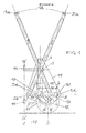
- Levers 1 and 2 have a common pivot point about a hinge shaft 3, which is arranged on a column 4 carrying an impeller 5 with an axis 6.
- connecting rod bearings 1b and 2b are provided, on which connecting rods 1c and 2c are pivotably arranged.
- the connecting rods 1c and 2c are guided on a circulating chain 9 with chain drivers 1d and 2d.
- the chain 9 runs over gears 7 'and 8th
- the swivel path of the handles 1a and 2a is designated by 18.
- the stroke of the connecting rods 1c and 2c is denoted by 15 and the center distance from the gear 7 'to the gear 8 with 16.
- the gear 7 ' is mounted on a shaft together with a gear 10 which transmits the driving force to a gear 12 via a chain 11, which is firmly connected to the impeller 5 and thus converts the force movements introduced into locomotion.
- the drive device is rotatably connected via pin arms 13 and 14 on an upper and lower connecting element to coupling elements of the wheelchair 15a and 16a (FIG. 2).
- the steering is done with a kink steering around the vertical axis xx.
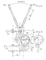
- a cover 19 is provided to protect the drive mechanism.
- the impeller 5 is pivoted about the radius 17.
- the connecting rods 1c and 2c are guided on shaft journals 22a on a gearwheel 22 which, via a chain 11a, transmits the force to the gearwheel 12 to which the impeller 5 is connected.
- a storage compartment 20 is also accommodated in the covering 19.
- the handles 1a and 1b can be inserted by means of a telescopic mechanism 21, so that any power lever ratios can be selected.
- a corresponding gear engagement 23, 24 is provided instead of the chain 11a.
- the translation can be selected in the form of a gear shift with several gear pairs.
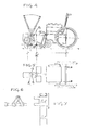
- FIGS. 4 and 5 show a conventional wheelchair which is coupled to a drive device as described above. There is an articulated steering around the axis x. After disconnecting the drive device, the wheelchair can be used again as before.
- the driver element is composed of several chain links in a triangular shape.
- the chain driver 2d connected to the connecting rod 2c engages in the chain like a plug.
- the two-armed levers 1 and 2 which are rotatably mounted on the hinge shaft 3 are divided.
- the respective upper lever arm 1e and 2e can be pulled out of the lower lever arm. This enables unhindered entry and exit. Nevertheless, there is the advantage that, after insertion, the levers 1, 2 are arranged directly in front of the chest area of the wheelchair user, so that there is a correspondingly effective drive with relatively little effort.
- the upper lever parts 1e and 2e can be pushed into a free holder on the associated outside of the wheelchair.
- the handles 1a and 2a are designed as rotary handles which are connected by Bowden cables to the steering mechanism of the front wheel or the front wheels 29 which can be rotated about the axis 29. When turning the rotary handles, the front wheels 29 are steered in the same direction. If a handbrake lever is attached to the rotary handles 1a and 2a, braking of the wheelchair is made possible via Bowden cables. These steering and braking functions are also maintained when the levers 1e and 2e are inserted into the brackets on both sides of the wheelchair, since the Bowden cables allow a corresponding free space for movement.
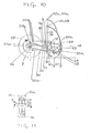
- two gears 1f and 1g or 2f and 2g and a chain spacer roller 1h and 2h are rotatably mounted at the lower end of the levers 1 and 2.
- the gear wheels 1f, 2f and 1g, 2g are each mounted on a freewheel, so that each gear wheel cannot be rotated in one direction of rotation - according to the arrows in the drawing in the clockwise direction.
- the power transmission from the gearwheels 1f and 1g or 2f and 2g to the chain 9 takes place in each case only through a gearwheel of a lever, while the second gearwheel moves in a freewheeling direction - counterclockwise according to the arrow in the drawing.
- a circulating chain 9 ' which runs over the gear 8 fixed between the feet on the wheelchair frame 31 and the gear 7 attached to the rear axle 26 and over a chain tensioner 25.
- the drive device is attached via the hinge joint 3 to the pivot arm 14 of the frame 30 of the wheelchair.
- the axis of the front wheel 29 is designated 28.
- the levers 1 and 2 are each rotatably mounted on the shaft 3 via anchoring plates 14a on the side wheelchair frame 30.
- the upper lever parts 1e and 2e each carry a handle 32, 33 and can be folded inwards from the positions 32a, 33a, ie when getting in and out the upper lever part is folded up or to the side with the handle.
- a closed frame element 34 is articulated to the lower part of the lever 1 or 2, which surrounds associated gears 7 with a free wheel arranged on the rear axle 26 of a rear wheel 27.
- the lower straight frame part and the upper straight frame part have opposing rack elements 35, 36, each of which engages with one of the two Gears 7 are on the rear wheel axle.
- the lower rack 36 is in engagement with one of the gears 7, the lever force being transmitted only in the direction of the arrow 36a. In the opposite direction of movement, the freewheel releases this counter movement, ie the gear moves in the opposite direction in the freewheel.
- the upper rack 35 transmits the lever force only in the direction of the arrow 35a. So that the racks 35, 36 remain in constant engagement with both gear wheels, they are held together at their end with a connecting element 34 a, which serves as a spacer.
- the connecting shaft between frame member 34 and lever 1, 2 is designated.
- 40a are bores or 40b a slot in the lever 1, 2 for receiving the connecting shaft 40, so that any lever arm length between the shaft 3 and shaft 40 can be selected.
- 39 is an articulated or flexible shaft.
- the toothed racks 35, 36 can also be designed in the form of a conductor rail or a chain can also be attached to a reinforcement frame and tensioned.
- each front wheel 29 is individually attached to the frame with its axle 28. It is therefore not possible to use a tie rod to steer the front wheels. Accordingly, the front wheel 29 is guided in its movement by the rotatable handle 32, 33 via a flexible shaft 39 fastened thereon in connection with an articulated shaft 38 of a guide plate 37 flanged thereon via the axis 28. Due to the caster 41 of the front wheel 29, only the steering of one front wheel 29 is required, since the second front wheel runs through the caster 41 of the predetermined path. The propeller shaft 38 of the front wheels 29 are held in place by a stiffening frame 30a.
Landscapes
- Health & Medical Sciences (AREA)
- Life Sciences & Earth Sciences (AREA)
- Animal Behavior & Ethology (AREA)
- General Health & Medical Sciences (AREA)
- Public Health (AREA)
- Veterinary Medicine (AREA)
- Engineering & Computer Science (AREA)
- General Engineering & Computer Science (AREA)
- Mechanical Engineering (AREA)
- Handcart (AREA)
Applications Claiming Priority (6)
| Application Number | Priority Date | Filing Date | Title |
|---|---|---|---|
| AT255987 | 1987-10-08 | ||
| AT2559/87 | 1987-10-08 | ||
| AT8588 | 1988-01-18 | ||
| AT85/88 | 1988-01-18 | ||
| AT2280/88 | 1988-09-19 | ||
| AT228088 | 1988-09-19 |
Publications (1)
| Publication Number | Publication Date |
|---|---|
| EP0318677A1 true EP0318677A1 (fr) | 1989-06-07 |
Family
ID=27145834
Family Applications (1)
| Application Number | Title | Priority Date | Filing Date |
|---|---|---|---|
| EP88116631A Withdrawn EP0318677A1 (fr) | 1987-10-08 | 1988-10-07 | Mécanisme d'entraînement manuel pour fauteuils roulants |
Country Status (1)
| Country | Link |
|---|---|
| EP (1) | EP0318677A1 (fr) |
Cited By (4)
| Publication number | Priority date | Publication date | Assignee | Title |
|---|---|---|---|---|
| US6764089B2 (en) * | 2002-03-20 | 2004-07-20 | Robert Drymalski | Manually powered drive mechanism and vehicle employing same |
| WO2004105672A1 (fr) * | 2003-05-30 | 2004-12-09 | Izumi, D.O.O. | Mecanisme de direction supplementaire pour vehicule actionne musculairement, destine a accelerer la reeducation d'un bras paralyse |
| US7195264B2 (en) | 2002-03-20 | 2007-03-27 | Robert Drymalski | Manually powered vehicle having improved steering |
| US7753386B2 (en) | 2002-03-20 | 2010-07-13 | Robert Drymalski | Steering mechanism and method for a manually powered vehicle |
Citations (7)
| Publication number | Priority date | Publication date | Assignee | Title |
|---|---|---|---|---|
| DE41444C (de) * | O. NEUHÄUSER in Pforzheim, Holzgartenstr. 8 | Endlose Kette, als Ersatz der Kurbel in Kurbelgetrieben | ||
| FR788398A (fr) * | 1934-07-11 | 1935-10-09 | Vimeux Ets | Perfectionnements aux transmissions mécaniques et applications en résultant |
| GB579539A (en) * | 1944-05-23 | 1946-08-07 | Benson George Willis Bartlett | Improvements in or relating to invalid and like carriages having hand-operated driving mechanism |
| US3994509A (en) * | 1976-01-28 | 1976-11-30 | Schaeffer Jerome E | Propulsion means for wheelchairs |
| DE3131679A1 (de) * | 1981-08-11 | 1983-03-03 | Klosner, Helmut, Prof. Dipl.-Ing. | Getriebe mit eingriffswechsel |
| EP0128448A2 (fr) * | 1983-06-13 | 1984-12-19 | Mobility Manufacturing Co. | Unité de propulsion et de direction amovible pour fauteuil roulant à propulsion par le malade |
| DE3414447A1 (de) * | 1984-04-17 | 1985-10-17 | Haase, Peter, 3508 Melsungen | Vorrichtung zur umsetzung von linearer schwingbewegung in drehbewegung und/oder zur umsetzung von drehbewegung in lineare schwingbewegung |
-
1988
- 1988-10-07 EP EP88116631A patent/EP0318677A1/fr not_active Withdrawn
Patent Citations (7)
| Publication number | Priority date | Publication date | Assignee | Title |
|---|---|---|---|---|
| DE41444C (de) * | O. NEUHÄUSER in Pforzheim, Holzgartenstr. 8 | Endlose Kette, als Ersatz der Kurbel in Kurbelgetrieben | ||
| FR788398A (fr) * | 1934-07-11 | 1935-10-09 | Vimeux Ets | Perfectionnements aux transmissions mécaniques et applications en résultant |
| GB579539A (en) * | 1944-05-23 | 1946-08-07 | Benson George Willis Bartlett | Improvements in or relating to invalid and like carriages having hand-operated driving mechanism |
| US3994509A (en) * | 1976-01-28 | 1976-11-30 | Schaeffer Jerome E | Propulsion means for wheelchairs |
| DE3131679A1 (de) * | 1981-08-11 | 1983-03-03 | Klosner, Helmut, Prof. Dipl.-Ing. | Getriebe mit eingriffswechsel |
| EP0128448A2 (fr) * | 1983-06-13 | 1984-12-19 | Mobility Manufacturing Co. | Unité de propulsion et de direction amovible pour fauteuil roulant à propulsion par le malade |
| DE3414447A1 (de) * | 1984-04-17 | 1985-10-17 | Haase, Peter, 3508 Melsungen | Vorrichtung zur umsetzung von linearer schwingbewegung in drehbewegung und/oder zur umsetzung von drehbewegung in lineare schwingbewegung |
Cited By (5)
| Publication number | Priority date | Publication date | Assignee | Title |
|---|---|---|---|---|
| US6764089B2 (en) * | 2002-03-20 | 2004-07-20 | Robert Drymalski | Manually powered drive mechanism and vehicle employing same |
| US7195264B2 (en) | 2002-03-20 | 2007-03-27 | Robert Drymalski | Manually powered vehicle having improved steering |
| US7753386B2 (en) | 2002-03-20 | 2010-07-13 | Robert Drymalski | Steering mechanism and method for a manually powered vehicle |
| US8157280B2 (en) | 2002-03-20 | 2012-04-17 | Morse Cycle Company Llc | Manually powered drive mechanism with steering member and vehicle employing same |
| WO2004105672A1 (fr) * | 2003-05-30 | 2004-12-09 | Izumi, D.O.O. | Mecanisme de direction supplementaire pour vehicule actionne musculairement, destine a accelerer la reeducation d'un bras paralyse |
Similar Documents
| Publication | Publication Date | Title |
|---|---|---|
| EP0506800B1 (fr) | Systeme d'entrainement pour des vehicules et appareils mus par la force musculaire, notamment des bicyclettes | |
| DE60303842T2 (de) | Klappbares Fahrrad | |
| EP0379218B1 (fr) | Dispositif de sport et d'exercices | |
| DE2537087A1 (de) | Fahrzeug fuer sport- bzw. vergnuegungszwecke | |
| DE69020363T2 (de) | Transporteinrichtung für invalide. | |
| DE2721180C2 (fr) | ||
| EP1301249B1 (fr) | Appareil de sport et de transport | |
| EP0320735B1 (fr) | Machine mobile de nettoyage de sols commandée manuellement | |
| EP0318677A1 (fr) | Mécanisme d'entraînement manuel pour fauteuils roulants | |
| DE69814989T2 (de) | Geländefahrzeug mit lenkbarer Vorderachse und Frontzapfwellenkupplung | |
| DE3239548A1 (de) | Fahrrad, das zum lenken und zum beschleunigen einen lenkbaren armkraftantriebsmechanismus aufweist | |
| CH654262A5 (de) | Lenkeinrichtung an einem selbstfahrenden landwirtschaftlichen arbeitsgeraet. | |
| DE60006386T2 (de) | Durch muskelkraft angebtriebenes fahrrad | |
| EP0204971B1 (fr) | Motofaucheuse à deux roues | |
| DE3831890C2 (fr) | ||
| DE4241057C2 (de) | Vorrichtung zum Antrieb einer Antriebswelle durch Muskelkraft | |
| DE3516322A1 (de) | Radfahrzeug mit antrieb durch den fahrer | |
| EP3954446B1 (fr) | Modèle réduit de voiture à friction ou à moteur à remonter | |
| DE3508579A1 (de) | Dreirad, insbesondere fuer behinderte personen | |
| DE899756C (de) | Schlepper auf vier gleich grossen Triebraedern | |
| DE9108229U1 (de) | Vorrichtung zum Umwandeln von Schwenkbewegungen in Kreisbewegungen | |
| DE202006006692U1 (de) | Fahrzeug, insbesondere nach Art eines Tretrollers | |
| AT369227B (de) | Lenkeinrichtung fuer ein selbstfahrendes landwirtschaftliches arbeitsgeraet | |
| DE125421C (fr) | ||
| DE1748493U (de) | Dreiradselbstfahrzeug, insbesondere fuer kinder. |
Legal Events
| Date | Code | Title | Description |
|---|---|---|---|
| PUAI | Public reference made under article 153(3) epc to a published international application that has entered the european phase |
Free format text: ORIGINAL CODE: 0009012 |
|
| AK | Designated contracting states |
Kind code of ref document: A1 Designated state(s): AT DE FR GB IT SE |
|
| STAA | Information on the status of an ep patent application or granted ep patent |
Free format text: STATUS: THE APPLICATION IS DEEMED TO BE WITHDRAWN |
|
| 18D | Application deemed to be withdrawn |
Effective date: 19891208 |