EP0128498A1 - Support de batterie pour un appareil de bande de cassette - Google Patents
Support de batterie pour un appareil de bande de cassette Download PDFInfo
- Publication number
- EP0128498A1 EP0128498A1 EP84106348A EP84106348A EP0128498A1 EP 0128498 A1 EP0128498 A1 EP 0128498A1 EP 84106348 A EP84106348 A EP 84106348A EP 84106348 A EP84106348 A EP 84106348A EP 0128498 A1 EP0128498 A1 EP 0128498A1
- Authority
- EP
- European Patent Office
- Prior art keywords
- cassette
- compartment
- box
- receptacle
- casing
- Prior art date
- Legal status (The legal status is an assumption and is not a legal conclusion. Google has not performed a legal analysis and makes no representation as to the accuracy of the status listed.)
- Granted
Links
Images


Classifications
-
- G—PHYSICS
- G11—INFORMATION STORAGE
- G11B—INFORMATION STORAGE BASED ON RELATIVE MOVEMENT BETWEEN RECORD CARRIER AND TRANSDUCER
- G11B33/00—Constructional parts, details or accessories not provided for in the other groups of this subclass
- G11B33/02—Cabinets; Cases; Stands; Disposition of apparatus therein or thereon
-
- G—PHYSICS
- G11—INFORMATION STORAGE
- G11B—INFORMATION STORAGE BASED ON RELATIVE MOVEMENT BETWEEN RECORD CARRIER AND TRANSDUCER
- G11B25/00—Apparatus characterised by the shape of record carrier employed but not specific to the method of recording or reproducing, e.g. dictating apparatus; Combinations of such apparatus
- G11B25/06—Apparatus characterised by the shape of record carrier employed but not specific to the method of recording or reproducing, e.g. dictating apparatus; Combinations of such apparatus using web-form record carriers, e.g. tape
- G11B25/063—Apparatus characterised by the shape of record carrier employed but not specific to the method of recording or reproducing, e.g. dictating apparatus; Combinations of such apparatus using web-form record carriers, e.g. tape using tape inside container
-
- G—PHYSICS
- G11—INFORMATION STORAGE
- G11B—INFORMATION STORAGE BASED ON RELATIVE MOVEMENT BETWEEN RECORD CARRIER AND TRANSDUCER
- G11B15/00—Driving, starting or stopping record carriers of filamentary or web form; Driving both such record carriers and heads; Guiding such record carriers or containers therefor; Control thereof; Control of operating function
- G11B15/675—Guiding containers, e.g. loading, ejecting cassettes
- G11B15/67581—Guiding containers, e.g. loading, ejecting cassettes with pivoting movement of the cassette holder
- G11B15/67584—Guiding containers, e.g. loading, ejecting cassettes with pivoting movement of the cassette holder outside the apparatus
Definitions
- This invention relates generally to cassette tape players, and more particularly is directed to the battery holders thereof.
- Battery operated portable cassette tape players are known in which the casing or cabinet of the player incorporates a box or holder for one or more batteries by which the player is to be operated. Recently, the trend has been to reduce as much as possible the size of portable cassette tape players, and the box or holder for the battery or batteries has become an important limiting factor in such trend towards miniaturization of cassette tape players.
- the cabinet of the cassette tape player includes a rectangular casing substantially corresponding, in its outlines, to the configuration of the housing of the cassette-to be used therein, and having a chassis extending across the casing to define a compartment for the cassette thereabove which is to be closed by a cover or lid pivoted on the casing. Situated below the chassis are the motor and other mechanisms for driving the tape in the cassette housing situated in the compartment thereabove.
- the chassis has an opening therein through which a battery or batteries may be conveniently loaded into a battery box or container disposed below the chassis and adapted to be closed by a battery cover which lies substantially flush with the chassis to cooperate with the latter in defining the bottom surface of the compartment for the cassette.
- a battery or batteries may be conveniently loaded into a battery box or container disposed below the chassis and adapted to be closed by a battery cover which lies substantially flush with the chassis to cooperate with the latter in defining the bottom surface of the compartment for the cassette.
- Still another object of the invention is to provide a portable cassette tape player, as aforesaid, in which the battery box or holder assists in locating a cassette housing in the chamber provided therefor.
- a cassette tape player is provided with a casing defining a compartment for receiving a cassette and which includes a hollow box-like structure extending only partly across the casing to confront a corresponding portion of a long side of the cassette housing, a battery receptacle extending longitudinally from the hollow box-like structure across substantially the remainder of the casing for receiving at least one elongated cylindrical battery with the longitudinal axis of the latter extending parallel with the long side of the cassette housing in the compartment, and a closure engageable with the battery receptacle for retaining and locating at least one battery in the receptacle and being configured to define, with the receptacle, a box-like extension of the hollow box-like structure which cooperates with the latter to define a substantially continuous surface for locating the cassette housing in the compartment.
- the cassette locating surface of the hollow box-like structure has spaced apart openings therein to register, at least partly, with respective conventional windows spaced apart in the peripheral wall of the cassette housing
- the cassette tape player further includes a reproducing head mounted within the hollow box-like structure and engageable through one of the openings and the registered window with the tape in the cassette housing, and a pressure roller also mounted within the hollow box-like structure and engageable with the tape through the other registered opening and window for urging the tape against a rotatable capstan which projects upwardly into a cassette housing located in the compartment.
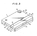
- the player 100 comprises a casing 1 which includes a main section la and an auxiliary section Ib movable relative to each other between a compact or contracted condition (Fig. 1) and an expanded or operative condition (Figs. 2-4).
- the main section la of casing 1 is desirably pressed of sheet metal and has a bottom wall 1a 1 (Figs. 3,7 and 9) with side walls la 2 and a front wall la 3 extending from the respective margins of bottom wall or base la l .
- the portions of base la 1 and side walls la 2 remote from front wall la 3 are inwardly offset, as indicated at 1a' 1 and 1a' 2 .
- side walls la 2 desirably are formed, along most of their lengths, to have a height approximately one-half the height of front wall la 3 .
- auxiliary section ib of casing 1 is shown to have a bottom wall 1b 1 slidable against the outer or under surface of the offset back portion 1a' 1 of the bottom wall or base 1a 1 of main section la, side walls Ib2 slidable against the outer surfaces of the offset back portions. 1a' 2 of side walls 1a 2 and a back wall 1b 3 (Fig. 3). Side walls 1b 2 and back wall 1b 3 desirably have a height approximately equal to the height of side walls 1a 2 along the major portion of the length of the latter.
- auxiliary section 1b of the casing is mounted for movement relative to main section 1a in the direction toward and away from the front wall 1a 3 of the latter between a contracted position (Fig. 1) in which player 100 is compact for ease in carrying or storing the . same, and an extended position (Figs. 2-4) in which a cassette 101 can be accommodated therein.
- main section la of casing 1 has a hollow, box-like structure 2 extending only slightly more than halfway across casing 1 immediately in back of front wall 1a 3 .
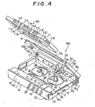
- a chassis 3a (Figs. 4,7 and 9) extends between side walls la 2 of main section 1a and is spaced from base or bottom wall 1a 1 to provide a space therebetween for accommodating mechanisms (not shown) for driving the tape of a cassette 101 operatively positioned within casing 1, and also for accommodating circuits by which recorded audio signals are reproduced.
- auxiliary section lb of casing 1 When auxiliary section lb of casing 1 is in its extended position relative to main section la, the resulting enlarged space or distance between box-like structure 2 and back wall lb 3 of the auxiliary casing section provides a compartment 3 above chassis 3a in casing 1 of a size sufficient to accommodate cassette 101 therein.
- a guide bracket 4 is suitably secured at the center of back wall lb 3 of the auxiliary casing section and extends forwardly therefrom- between chassis 3a and the bottom wall la 1 of main section la for guiding and limiting the relative movements of the casing sections and for yieldably retaining sections la and lb in their extended and contracted positions relative to each other, as hereinafter described in detail.
- Portable cassette tape player 100 is further shown to have a lid or cover 5 constituted by a top wall 5a and side walls 5b and a back wall 5c depending from the respective margins of top wall 5a and having a height approximately equal to one-half the height of front wall 1a3.
- Cover 5 is hingedly mounted on casing 1 by means of a piano hinge 6 connecting back walls 1b 3 and 5c of auxiliary casing section lb and cover 5, respectively.
- Positioning brackets 7 and 7' are secured at the inner sides of side walls 1b 2 of auxiliary casing section lb adjacent back wall lb 3 and are engageable with cover 5, as hereinafter described in detail, for releasably retaining the cover in either its closed position (Figs. 1-3) or its pivotally raised or opened position (Figs. 4 and 6).
- guide bracket 4 which is desirably formed of resilient or spring metal, includes a laterally extending base portion . 4a secured to the inner surface of back wall 1b 3 , and a pair of laterally spaced guide arms 4b and 4c extending forwardly from base portion 4a and defining a slot 4d therebetween.
- Arms 4b and 4c have inwardly directed rounded ends 4b' and 4c', and arm 4b is substantially longer than arm 4c.
- rounded ends 4b' and 4c' restrict slot 4d at spaced apart locations along the forward end portion of the slot.
- resilient fingers 4e and 4f extend from arms 4b and 4c, respectively, and are slightly angled toward each other for narrowing or restricting slot 4d adjacent base portion 4a which is formed with a central arcuate recess 4g.
- Guide bracket 4 is located so that its arms 4b and 4c extend forwardly from back wall Ib 3 of casing section lb in the space between chassis 3a and bottom wall la' of casing section la.
- a pin 8 (Fics. 4 and 5) depends centrally from chassis 3a adjacent the back edge of the latter and is received in slot 4d.
- Pin 8 is diametrically dimensioned to fit relatively closely in slot 4d so that, when auxiliary casing section lb is in its contracted position relative to main casing section la, pin 8 will be in back of, and resiliently acted upon by the ends of fingers 4e and 4f so as to be yieldably held against arcuate recess 4g, thereby providing a detent action for retaining casing sections la and lb in the contracted condition.
- each of the positioning brackets 7,7' is also formed of resilient or spring metal and includes a generally sector-shaped body 7" with a tab extending therefrom and having a hole 7a for receiving an adjacent end of the pin of hinge 6.
- the sector-shaped body 7" is formed with an arcuate slot 7b concentric with hole 7a and being defined between outer and inner arcuate fingers 7c and 7d, respectively, which extend in opposite directions toward their free ends.
- a pin 9 projects inwardly from each cover side wall 5b into the slot 7b of the adjacent positioning bracket 7 or 7'.
- a rounded enlargement 7d' is formed at the free end of finger 7d and is located across slot 7b from a rounded enlargement 7c" provides en finger 7c so that slot 7b is narrowed or restricted at the location between rounded enlargements 7d' and 7c".
- slot 7b opens into a rounded end portion 7b".
- the free end portion of finger 7c is formed with an inwardly enlarged end portion 7c', while the opposite edge of slot 7b is formed with an arcuate recess 7b'.
- each of the positioning brackets 7,7' has a forwardly directed guide member 7e which is spaced inwardly from the adjacent side wall 1b 2 of auxiliary casing section Ib so as to be slidable against the inner surface of the offset rear portion 1a' 2 of the adjacent side wall of main casing section la.
- a projection 7e' extends upwardly from the forward end of guide member 7e, and a pin 10 is directed inwardly from side wall portion 1a '2 and is slidable along the upper edge of guide member 7e to engage projection 7e' when casing sections la and 1b are in their relatively extended condition shown on FIg. 6.
- each guide member 7e there is an inwardly directed tab 7f which is riveted or otherwise secured to the back wall 1b 3 of casing section 1b for securely anchoring the respective positioning bracket 7,7' in respect to the auxiliary casing section lb.
- each of the pins 9 moves upwardly along the respective arcuate slot 7b past the rounded enlargement 7c' at the free end of finger 7c which acts as a detent for holding the respective pin 9 in the arcuate recess 7b'.
- the cover 5 is releasably retained in its opened position.
- each pin 9 is forced past the detent constituted by the rounded enlargement 7c' at the end of resilient finger 7c and then moves along arcuate slot 7b past the restriction therein constituted by the rounded enlargement 7c" and the end 7d l of resilient finger 7d and which form another detent for holding the respective pin 9 in the rounded end portion 7b" of the slot with cover 5 in its closed position. Accordingly, cover 5 is then yieldably held in its closed position until it is manually raised to force each pin 9 past rounded enlargement 7c".
- each positioning bracket 7,7' in bearing slidably against the inner surface of the adjacent side wall portion la'2 while the outer surface of the latter is slidably engaged by adjacent side wall lb 2 ensures that the front wall 1a 3 and back wall 1b 3 of casing sections 1a and 1b, respectively, remain parallel to each other while moving between their extended and contracted conditions. Furthermore, the engagement of each pin 10 against the upper edge of the respective guide member 7e in any position of auxiliary casing section 1b relative to main casing section la, and the engagement of pin 10 with projection 7e' in the relatively Extended condition of the casing sections serve to avoid relative rotational movements of casing sections la and Ib when cover 5 is angularly displaced between its opened and closed positions.
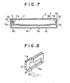
- a laterally resilient tab 12 depends from the top wall 5a of cover 5 at a location spaced a relatively small distance inwardly from one of side walls 5b.
- Such laterally resilient tab 12 is formed with an inwardly opening shallow groove 12a which is adapted to receive one of the similarly shaped projections lla and 11a' conventionally extending from the peripheral wall of the cassette housing 11 at the opposed relatively short sides thereof, as indicated in dot-dash lines.
- the bottom edge of laterally resilient tab 12 is bevelled, as indicated at 12b on Figs. 7 and 8.
- the side wall 5b of cover 5 remote from tab 12 is formed with an inwardly opening shallow groove 12a' adapted to receive the adjacent projection lla' on the cassette housing 11.
- housing 11 of a cassette 101 can be slidably inserted downwardly and rearwardly into opened cover 5 with projection lla' at one short side of the cassette housing being received in the groove 12a' of one of the cover side walls 5b, while the projection 11a at the opposite short side of the cassette housing is slidably received in the groove 12a of tab 12. Thereafter, when cover 5 is moved downwardly to its closed position, housing 11 of a cassette 101 previously disposed in the cover will be carried thereby into an operative position in compartment 3.
- cover 5 When cover 5 is subsequently raised to its opened position, the engagement of projections lla and lla' in grooves 12a and 12a' of cover 5 causes the cassette housing 11 to be carried along with the cover, and thereby removed from compartment 3, to the opened position of the cover at which the cassette can be easily removed.
- a cassette 101 can be loaded directly into compartment 3.
- cover 5 is thereafter displaced downwardly to its closed position, the bevelled lower edge 12b of laterally resilient tab 12 rides downwardly over projection lla on the adjacent short side of the cassette housing while tab 12 flexes outwardly until, in the fully closed position of the cover, projection lla engages in groove 12a and the other projection lla' engages in groove 12a'.
- the cassette in compartment 3 is again carried upwardly by the cover 5 by reason of the engagement of projections lla and lla' in grooves 12a and 12a', respectively.
- the gererally rectangular housing 11 of a standard cassette 101 has laterally spaced apart openings 11b and 11b' in its opposed panels or top and bottom walls through which supply and take-up reel shafts 26 and 26' extending upwardly from chassis 3a can project for engagement with supply and take-up reels (not shown) within cassette housing 11 when the latter is operatively positioned in compartment 3.
- Housing 11 of the conventional cassette 101 is further shown to have a central window lle and two opposite side windows 11f and 11f' spaced apart along a relatively long side of the peripheral wall of rectangular housing 11.
- the tape lIt wound on the supply and take-up reels in the housing is guided in a run therebetween along the long side of the housing having windows 11e, 11f and 11f' therein for exposure of the tape at such windows.
- the top and bottom walls of housing 11 are also formed with aligned openings 11c and 11c' disposed in back of windows 11f and 11f', respectively, and with aligned openings 11d and 11d' located between windows lle and 11f and between windows 11e and 11f', respectively.
- a capstan 27 extending upwardly from chassis 3a in back of box-like structure 2 is received in the openings lie or 11c', depending upon the orientation of the cassette 101 as placed in compartment 3, so as to dispose the capstan 27 immediately in back of the tape 11t exposed at the window 11f or 11f'.
- a pair of suitably spaced apart locating pins 28 and 28' extend upwardly frm chassis 3a for engagement in the openings lid and 11d' of the housing 11 of a cassette disposed in compartment 3, and serve to accurately position the cassette within such compartment.
- a series of push-buttons 29 (Figs. 1,2 and 4) are shown to extend from front wall 1a 3 of casing section 1a and are selectively operable for establishing respective modes of player 100, for example, the reproducing mode, the fast- forward mode, the rewind mode and the stop mode, by means of suitable mode selecting mechanisms (not shown) contained in the space between the chassis 3a and bottom wall 1a 1 and which form no part of the present invention.
- a rotatable volume control knob 30 is mounted on bottom wall la l adjacent a corner of casing 1 to which box-like structure 2 extends (Figs. 2 and 3).
- switch actuators 31 and 32 (Fig. 1) extend from one of the side walls la 2 to permit user control of associated circuits, for. example, circuits adapting the player 100 for use with different types of magnetic tapes, and a Dolby noise- reduction circuit, respectively.
- Leaf springs 33 may extend through cutouts 4a' (Fig. 5) in the base portion of guide bracket 4 so that, when a cassette 101 is disposed in compartment 3, leaf springs 33 will act against the long side of cassette housing 11 remote from the side having windows lle,llf and 11f' for urging the cassette housing forwardly, that is, in the direction toward box-like structure 2.
- the box-like structure 2 has a top wall 15 extending rearwardly from adjacent the top of front wall 1a 3 and a back wall 15' which, when a cassette 101 is operatively positioned in compartment 3 confronts a corresponding portion of the long side of the cassette housing provided with windows 11e, 11f and 11f'.
- the cassette tape player 100 to which the present invention is shown to be applied is adapted only for reproducing or playback operation, and hence has only a reproducing magnetic head 13 which is suitably mounted within hollow box-like structure 2 at an opening 15a provided in back wall 15' at the middle of compartment 3.
- the reproducing or playback magnetic head 13 is engageable through opening 15a and through the registered middle window lle of the cassette housing with the tape lIt exposed at such window.
- Back wall 15' of box-like structure 2 is shown to have another opening 15b located to register, at least partly, with one or the other of the side windows 11f and 11f' of the cassette housing 11 disposed in compartment 3.
- a pressure roller 14 is suitably mounted within box-like structure 2 and is engageable through opening 15b and the registered window llf or llf' with the tape lIt exposed at such window for urging the engaged tape against the capstan 27 extending upwardly in the openings 11c or 11c'.
- top wall 15 of box-like structure 2 may be provided with a hole 19 through which a screwdriver or other tool may have access to a mechanism (not shown) for adjusting the azimuth angle of head 13.
- a jack 20 may be provided in the end wall of box-like structure 2 adjacent a side wall 1a 2 and is adapted to receive a plug for supplying the output audio signal to headphones (not shown).
- a battery receptacle 15c (Fig. 9), which is preferably integral with box-like structure 2, extends longitudinally from structure 2 across substantially the remainder of the casing 1 for receiving at least one elongated cylindrical battery indicated in dot-dash lines at 16.
- Each such cylindrical battery 16 is arranged with its longitudinal axis extending parallel to the long side of a cassette housing 11 disposed in compartment 3 which faces back surface 15' of box-like structure 2.
- a closure 18 is engageable with battery receptacle 15c for retaining and locating the at least one battery 16 in such receptacle. .
- the closure 18 is configured to define, with the receptacle 15c, a battery box 17 which constitutes a box-like extension of the hollow box-like structure 2 and which cooperates with the latter to define a substantially continuous surface across the front of compartment 3 for locating the cassette housing therein.
- the closure 18 of the battery box 17 is shown to include an inner cover member 21, a latch 22 and an outer cover member 23.
- Inner cover member 21 is shown to be formed with right-angularly related wall portions 21' and 21". Relatively shallow, communicating grooves 21a and 21b are formed in the outer surfaces of wall portions 21' and 21", respectively, for accommodating the latch 22, as hereinafter described.
- Battery receptacle 15c has fixed end walls provided, near the top portions thereof, with keepers 24 and 25. Projections 21c extend from the end of wall portion 21' of inner cover member 21 which is remote from groove 21a and such projections 21c are engageable in keeper 24.
- Latch 22 which is desirably formed of a resilient plastic or resin is shown to include an elongated body 22a slidable in groove 21a and having a locking end portion 22a' adapted to project from groove 21a beyond the adjacent end of wall portion 21' for engagement with keeper 25.
- latch 22 is shown to include an actuating portion 22b depending from one side of body 22a and being slidable in groove 22b of wall portion 21".
- the actuating portion 22b is shown to have a raised knurled or roughened surface 22b' by which latch 22 can be manually displaced along-grooves 21a and 21b in the direction opposed to the force of spring portion 22a" for releasing locking end portion 22a' from keeper 25 and thereby permitting removal of closure 18 for insertion or replacement of batteries in battery box 17.
- the outer or finishing cover member 23 extends over cover member 21 for retaining latch 22 in grooves 21a and 21b.
- Outer cover member 23 is shown to include right'angularly related wall portions 23' and 23" which are superposed on wall portions 21' and 21", respectively, and suitably secured thereto.
- Wall portion 23" is shown to have an aperture or slot 23a through which raised surface portion 22b' of the actuating portion 22b of latch 22 can extend for manipulation by the user.
- Outer cover member 23 is dimensioned so that when the assembled closure 18 is installed on receptacle 15c with projections 21c engaging keeper 24 and locking end portion 22a' of latch 22 engaging keeper 25, the exterior surfaces of wall portions 23' and 23" will be substantially flush continuations of the external surfaces of wall portions 15 and 15' of box-like structure 2.
- the cassette tape player 100 to which the present invention is applied is capable of only reproducing or playback operation, that is, it is not capable of recording operation.
- player 100 does not require or employ an erasing head which would otherwise be disposed at the position occupied by battery box 17 for erasing signals previously recorded on the tape prior to the recording of new signals thereon by the head 13.
- the long side of the cassette housing 11 provided with windows lle,llf and llf' is engageable, and accurately located by the contiguous outer surfaces of wall portions 15' and 23". It will be appreciated that, in such case, the surface of wall portion 23" will confront the window llf or llf' of the cassette housing through which an erasing head would be engageable with the tape in a cassette tape recording and reproducing apparatus.
- the casing 1, with such battery box accommodated therein can be reduced in size, and particularly in the thickness thereof.
- the overall size of player 100 can be substantially that of the cassette housing 11.
- the compartment 3 becomes sufficiently large to accommodate the cassette housing 11 while the top wall 5a of cover or lid 5, at its forward edge portion, continues to engage the external surfaces of the contiguous wall portions 15 and 23' for closing compartment 3 with a cassette 101 therein.
- cover or lid 5 when cover or lid 5 is pivoted to its opened position and closure 18 is released from engagement with battery receptacle 15c, such receptacle then opens upwardly and rearwardly for ease in removing and installing the battery or batteries 16 in receptacle ISc.
Landscapes
- Casings For Electric Apparatus (AREA)
- Battery Mounting, Suspending (AREA)
- Automatic Tape Cassette Changers (AREA)
- Packaging Of Annular Or Rod-Shaped Articles, Wearing Apparel, Cassettes, Or The Like (AREA)
- Fittings On The Vehicle Exterior For Carrying Loads, And Devices For Holding Or Mounting Articles (AREA)
- Power Steering Mechanism (AREA)
- Printers Characterized By Their Purpose (AREA)
Applications Claiming Priority (2)
| Application Number | Priority Date | Filing Date | Title |
|---|---|---|---|
| JP1983084948U JPS59189703U (ja) | 1983-06-03 | 1983-06-03 | カセツト式テ−プレコ−ダ |
| JP84948/83 | 1983-06-03 |
Publications (2)
| Publication Number | Publication Date |
|---|---|
| EP0128498A1 true EP0128498A1 (fr) | 1984-12-19 |
| EP0128498B1 EP0128498B1 (fr) | 1989-04-12 |
Family
ID=13844857
Family Applications (1)
| Application Number | Title | Priority Date | Filing Date |
|---|---|---|---|
| EP84106348A Expired EP0128498B1 (fr) | 1983-06-03 | 1984-06-04 | Support de batterie pour un appareil de bande de cassette |
Country Status (10)
| Country | Link |
|---|---|
| US (1) | US4661865A (fr) |
| EP (1) | EP0128498B1 (fr) |
| JP (1) | JPS59189703U (fr) |
| KR (3) | KR890003474Y1 (fr) |
| AT (1) | ATE42160T1 (fr) |
| AU (1) | AU560718B2 (fr) |
| BR (1) | BR8402684A (fr) |
| CA (1) | CA1223660A (fr) |
| DE (1) | DE3477707D1 (fr) |
| ES (1) | ES287381Y (fr) |
Cited By (3)
| Publication number | Priority date | Publication date | Assignee | Title |
|---|---|---|---|---|
| GB2250126A (en) * | 1990-10-22 | 1992-05-27 | Star Touch Limited | Cassette deck with integrated battery compartment |
| EP0600704A3 (en) * | 1992-11-30 | 1994-08-10 | Sony Corp | Cassette accommodating type electronic equipment. |
| EP0644546A1 (fr) * | 1993-09-20 | 1995-03-22 | Sony Corporation | Equipement électronique |
Families Citing this family (7)
| Publication number | Priority date | Publication date | Assignee | Title |
|---|---|---|---|---|
| JPS6124818U (ja) * | 1984-07-19 | 1986-02-14 | ソニー株式会社 | カセツト式テ−プレコ−ダ |
| SE450436B (sv) * | 1986-10-03 | 1987-06-22 | Glasforskningsinstitutet | Bildskerm med reducerat elektrostatiskt felt samt sett och medel for framstellning av bildskermen |
| CA1332757C (fr) * | 1988-11-09 | 1994-10-25 | Takao Kumagai | Dispositif de chargement de cassette de bande magnetique incorpore a un appareil d'enregistrement et/ou de lecture |
| USD330391S (en) | 1990-11-09 | 1992-10-20 | Lawrence Cole | Combined newspaper rack and support |
| WO1998030074A1 (fr) * | 1996-12-26 | 1998-07-09 | Sony Corporation | Dispositif electronique |
| EP0957488A1 (fr) * | 1998-05-14 | 1999-11-17 | THOMSON multimedia | Couvercle de lecteur remplacable par l'utilisateur |
| TWI253776B (en) * | 2005-08-03 | 2006-04-21 | Lite On Technology Corp | Portable electronic device capable of pushing up a battery cover while moving a latch |
Citations (4)
| Publication number | Priority date | Publication date | Assignee | Title |
|---|---|---|---|---|
| DE2264052A1 (de) * | 1971-12-29 | 1973-07-05 | Olympus Optical Co | Superminiatur-kassetten-tonbandgeraet |
| US3964808A (en) * | 1974-12-04 | 1976-06-22 | Technical Incorporated | All-plastic housing for a small compact tape reproducer and recorder |
| GB2088616A (en) * | 1980-10-09 | 1982-06-09 | Mitsubishi Electric Corp | Portable acoustic device |
| GB2091023A (en) * | 1980-12-29 | 1982-07-21 | Balda Werke Photographische | Pocket dictating device |
Family Cites Families (2)
| Publication number | Priority date | Publication date | Assignee | Title |
|---|---|---|---|---|
| US3521010A (en) * | 1965-12-28 | 1970-07-21 | Olympus Optical Co | Ultraminiature tape recorder with components detachable from the main body |
| JPS57113449A (en) * | 1980-12-29 | 1982-07-14 | Sony Corp | Tape driver |
-
1983
- 1983-06-03 JP JP1983084948U patent/JPS59189703U/ja active Granted
- 1983-07-21 KR KR2019840005056U patent/KR890003474Y1/ko not_active Expired
- 1983-07-21 KR KR2019830006429U patent/KR890003476Y1/ko not_active Expired
-
1984
- 1984-05-28 AU AU28744/84A patent/AU560718B2/en not_active Ceased
- 1984-05-29 CA CA000455321A patent/CA1223660A/fr not_active Expired
- 1984-05-29 KR KR2019840005057U patent/KR890003475Y1/ko not_active Expired
- 1984-05-31 US US06/615,791 patent/US4661865A/en not_active Expired - Fee Related
- 1984-06-01 BR BR8402684A patent/BR8402684A/pt not_active IP Right Cessation
- 1984-06-02 ES ES1984287381U patent/ES287381Y/es not_active Expired
- 1984-06-04 DE DE8484106348T patent/DE3477707D1/de not_active Expired
- 1984-06-04 AT AT84106348T patent/ATE42160T1/de not_active IP Right Cessation
- 1984-06-04 EP EP84106348A patent/EP0128498B1/fr not_active Expired
Patent Citations (4)
| Publication number | Priority date | Publication date | Assignee | Title |
|---|---|---|---|---|
| DE2264052A1 (de) * | 1971-12-29 | 1973-07-05 | Olympus Optical Co | Superminiatur-kassetten-tonbandgeraet |
| US3964808A (en) * | 1974-12-04 | 1976-06-22 | Technical Incorporated | All-plastic housing for a small compact tape reproducer and recorder |
| GB2088616A (en) * | 1980-10-09 | 1982-06-09 | Mitsubishi Electric Corp | Portable acoustic device |
| GB2091023A (en) * | 1980-12-29 | 1982-07-21 | Balda Werke Photographische | Pocket dictating device |
Cited By (4)
| Publication number | Priority date | Publication date | Assignee | Title |
|---|---|---|---|---|
| GB2250126A (en) * | 1990-10-22 | 1992-05-27 | Star Touch Limited | Cassette deck with integrated battery compartment |
| EP0600704A3 (en) * | 1992-11-30 | 1994-08-10 | Sony Corp | Cassette accommodating type electronic equipment. |
| EP0644546A1 (fr) * | 1993-09-20 | 1995-03-22 | Sony Corporation | Equipement électronique |
| US5541809A (en) * | 1993-09-20 | 1996-07-30 | Sony Corporation | Electronic equipments chassis made from bent sheet metal |
Also Published As
| Publication number | Publication date |
|---|---|
| KR890003476Y1 (ko) | 1989-05-25 |
| US4661865A (en) | 1987-04-28 |
| ATE42160T1 (de) | 1989-04-15 |
| AU560718B2 (en) | 1987-04-16 |
| KR890003475Y1 (ko) | 1989-05-25 |
| CA1223660A (fr) | 1987-06-30 |
| ES287381Y (es) | 1986-07-16 |
| KR890003474Y1 (ko) | 1989-05-25 |
| JPS6343676Y2 (fr) | 1988-11-14 |
| AU2874484A (en) | 1984-12-06 |
| ES287381U (es) | 1985-12-16 |
| DE3477707D1 (en) | 1989-05-18 |
| EP0128498B1 (fr) | 1989-04-12 |
| JPS59189703U (ja) | 1984-12-15 |
| BR8402684A (pt) | 1985-05-07 |
| KR850000972U (ko) | 1985-03-30 |
Similar Documents
| Publication | Publication Date | Title |
|---|---|---|
| EP0578536A2 (fr) | Mécanisme d'ouverture/fermeture de porte et appareil comportant ce mécanisme | |
| JPH0565946B2 (fr) | ||
| EP0760154A1 (fr) | Unite d'entrainement pouvant recevoir des cartouches de supports de donnees de differentes tailles, et cartouches associees | |
| JPH11185433A (ja) | 磁気テープカートリッジ | |
| US4661865A (en) | Battery holder of single head minimum size cassette tape player | |
| EP0189324B1 (fr) | Compartiment de cassette dans un appareil d'enregistrement et de reproduction pour cassettes à bande magnétique | |
| US4139875A (en) | Cassette and card recording and/or reproducing apparatus | |
| JPH11213615A (ja) | 磁気テープカートリッジ | |
| JPH11297032A (ja) | 磁気テープカートリッジ | |
| KR0143781B1 (ko) | 테이프 카셋트 어댑터 | |
| EP0415083B1 (fr) | Boîtier d'emmagasinage de cassette | |
| JPH0447820Y2 (fr) | ||
| US5224004A (en) | Tape cassette having reels displaceable towards the rear corners | |
| JP3989622B2 (ja) | 磁気テープカートリッジ | |
| JPH11297034A (ja) | 磁気テープカートリッジ | |
| US5894377A (en) | Tray loading cartridge tape drive for different sized cartridges | |
| JP2000076821A (ja) | 磁気テープカートリッジ | |
| JPH11213613A (ja) | 磁気テープカートリッジ | |
| JP3989613B2 (ja) | 磁気テープカートリッジ | |
| JP2964882B2 (ja) | 磁気テープ駆動装置 | |
| JP3326667B2 (ja) | 電子機器用接続装置 | |
| JP3495750B2 (ja) | 携帯型テープレコーダ装置 | |
| JPS6317054Y2 (fr) | ||
| JPH0810867Y2 (ja) | カセツト装着機構 | |
| JP4434430B2 (ja) | 記録再生装置の蓋開閉装置 |
Legal Events
| Date | Code | Title | Description |
|---|---|---|---|
| PUAI | Public reference made under article 153(3) epc to a published international application that has entered the european phase |
Free format text: ORIGINAL CODE: 0009012 |
|
| AK | Designated contracting states |
Designated state(s): AT DE FR GB IT NL |
|
| 17P | Request for examination filed |
Effective date: 19850417 |
|
| 17Q | First examination report despatched |
Effective date: 19861013 |
|
| GRAA | (expected) grant |
Free format text: ORIGINAL CODE: 0009210 |
|
| AK | Designated contracting states |
Kind code of ref document: B1 Designated state(s): AT DE FR GB IT NL |
|
| REF | Corresponds to: |
Ref document number: 42160 Country of ref document: AT Date of ref document: 19890415 Kind code of ref document: T |
|
| REF | Corresponds to: |
Ref document number: 3477707 Country of ref document: DE Date of ref document: 19890518 |
|
| ET | Fr: translation filed | ||
| ITF | It: translation for a ep patent filed | ||
| PLBE | No opposition filed within time limit |
Free format text: ORIGINAL CODE: 0009261 |
|
| STAA | Information on the status of an ep patent application or granted ep patent |
Free format text: STATUS: NO OPPOSITION FILED WITHIN TIME LIMIT |
|
| 26N | No opposition filed | ||
| ITTA | It: last paid annual fee | ||
| PGFP | Annual fee paid to national office [announced via postgrant information from national office to epo] |
Ref country code: GB Payment date: 19960528 Year of fee payment: 13 |
|
| PGFP | Annual fee paid to national office [announced via postgrant information from national office to epo] |
Ref country code: AT Payment date: 19960613 Year of fee payment: 13 |
|
| PG25 | Lapsed in a contracting state [announced via postgrant information from national office to epo] |
Ref country code: GB Free format text: LAPSE BECAUSE OF NON-PAYMENT OF DUE FEES Effective date: 19970604 Ref country code: AT Effective date: 19970604 |
|
| PGFP | Annual fee paid to national office [announced via postgrant information from national office to epo] |
Ref country code: FR Payment date: 19970610 Year of fee payment: 14 |
|
| PGFP | Annual fee paid to national office [announced via postgrant information from national office to epo] |
Ref country code: NL Payment date: 19970630 Year of fee payment: 14 |
|
| GBPC | Gb: european patent ceased through non-payment of renewal fee |
Effective date: 19970604 |
|
| PG25 | Lapsed in a contracting state [announced via postgrant information from national office to epo] |
Ref country code: NL Free format text: LAPSE BECAUSE OF NON-PAYMENT OF DUE FEES Effective date: 19990101 |
|
| PG25 | Lapsed in a contracting state [announced via postgrant information from national office to epo] |
Ref country code: FR Free format text: LAPSE BECAUSE OF NON-PAYMENT OF DUE FEES Effective date: 19990226 |
|
| NLV4 | Nl: lapsed or anulled due to non-payment of the annual fee |
Effective date: 19990101 |
|
| REG | Reference to a national code |
Ref country code: FR Ref legal event code: ST |
|
| PGFP | Annual fee paid to national office [announced via postgrant information from national office to epo] |
Ref country code: DE Payment date: 20020612 Year of fee payment: 19 |
|
| PG25 | Lapsed in a contracting state [announced via postgrant information from national office to epo] |
Ref country code: DE Free format text: LAPSE BECAUSE OF NON-PAYMENT OF DUE FEES Effective date: 20040101 |