EP0128511A1 - Poste de reproduction de télévision - Google Patents
Poste de reproduction de télévision Download PDFInfo
- Publication number
- EP0128511A1 EP0128511A1 EP84106424A EP84106424A EP0128511A1 EP 0128511 A1 EP0128511 A1 EP 0128511A1 EP 84106424 A EP84106424 A EP 84106424A EP 84106424 A EP84106424 A EP 84106424A EP 0128511 A1 EP0128511 A1 EP 0128511A1
- Authority
- EP
- European Patent Office
- Prior art keywords
- housing
- base
- playback device
- runners
- inclination
- Prior art date
- Legal status (The legal status is an assumption and is not a legal conclusion. Google has not performed a legal analysis and makes no representation as to the accuracy of the status listed.)
- Granted
Links
- 230000005484 gravity Effects 0.000 claims abstract description 6
- 239000002184 metal Substances 0.000 claims description 4
- 238000013459 approach Methods 0.000 claims 1
- 239000000463 material Substances 0.000 description 2
- -1 polytetrafluoroethylene Polymers 0.000 description 2
- 229920001343 polytetrafluoroethylene Polymers 0.000 description 2
- 239000004810 polytetrafluoroethylene Substances 0.000 description 2
- 229910000831 Steel Inorganic materials 0.000 description 1
- 239000000853 adhesive Substances 0.000 description 1
- 238000011161 development Methods 0.000 description 1
- 230000018109 developmental process Effects 0.000 description 1
- 230000002349 favourable effect Effects 0.000 description 1
- 239000004033 plastic Substances 0.000 description 1
- 238000004080 punching Methods 0.000 description 1
- 239000010959 steel Substances 0.000 description 1
- 230000000007 visual effect Effects 0.000 description 1
Images

Classifications
-
- H—ELECTRICITY
- H04—ELECTRIC COMMUNICATION TECHNIQUE
- H04N—PICTORIAL COMMUNICATION, e.g. TELEVISION
- H04N5/00—Details of television systems
- H04N5/64—Constructional details of receivers, e.g. cabinets or dust covers
-
- F—MECHANICAL ENGINEERING; LIGHTING; HEATING; WEAPONS; BLASTING
- F16—ENGINEERING ELEMENTS AND UNITS; GENERAL MEASURES FOR PRODUCING AND MAINTAINING EFFECTIVE FUNCTIONING OF MACHINES OR INSTALLATIONS; THERMAL INSULATION IN GENERAL
- F16M—FRAMES, CASINGS OR BEDS OF ENGINES, MACHINES OR APPARATUS, NOT SPECIFIC TO ENGINES, MACHINES OR APPARATUS PROVIDED FOR ELSEWHERE; STANDS; SUPPORTS
- F16M11/00—Stands or trestles as supports for apparatus or articles placed thereon ; Stands for scientific apparatus such as gravitational force meters
- F16M11/02—Heads
- F16M11/04—Means for attachment of apparatus; Means allowing adjustment of the apparatus relatively to the stand
- F16M11/06—Means for attachment of apparatus; Means allowing adjustment of the apparatus relatively to the stand allowing pivoting
- F16M11/10—Means for attachment of apparatus; Means allowing adjustment of the apparatus relatively to the stand allowing pivoting around a horizontal axis
-
- F—MECHANICAL ENGINEERING; LIGHTING; HEATING; WEAPONS; BLASTING
- F16—ENGINEERING ELEMENTS AND UNITS; GENERAL MEASURES FOR PRODUCING AND MAINTAINING EFFECTIVE FUNCTIONING OF MACHINES OR INSTALLATIONS; THERMAL INSULATION IN GENERAL
- F16M—FRAMES, CASINGS OR BEDS OF ENGINES, MACHINES OR APPARATUS, NOT SPECIFIC TO ENGINES, MACHINES OR APPARATUS PROVIDED FOR ELSEWHERE; STANDS; SUPPORTS
- F16M11/00—Stands or trestles as supports for apparatus or articles placed thereon ; Stands for scientific apparatus such as gravitational force meters
- F16M11/20—Undercarriages with or without wheels
- F16M11/2007—Undercarriages with or without wheels comprising means allowing pivoting adjustment
- F16M11/2014—Undercarriages with or without wheels comprising means allowing pivoting adjustment around a vertical axis
-
- F—MECHANICAL ENGINEERING; LIGHTING; HEATING; WEAPONS; BLASTING
- F16—ENGINEERING ELEMENTS AND UNITS; GENERAL MEASURES FOR PRODUCING AND MAINTAINING EFFECTIVE FUNCTIONING OF MACHINES OR INSTALLATIONS; THERMAL INSULATION IN GENERAL
- F16M—FRAMES, CASINGS OR BEDS OF ENGINES, MACHINES OR APPARATUS, NOT SPECIFIC TO ENGINES, MACHINES OR APPARATUS PROVIDED FOR ELSEWHERE; STANDS; SUPPORTS
- F16M2200/00—Details of stands or supports
- F16M2200/04—Balancing means
- F16M2200/041—Balancing means for balancing rotational movement of the head
Definitions
- the invention relates to a television display device with a picture tube containing housing which, in an arcuate guide contained in a base about an axis extending parallel to the screen plane ho - is held tiltably zontal axis.
- an adjustable tilt mechanism for visual display devices which has a base with a cylindrical recess.
- a corresponding cylinder surface is attached to the underside of the display device.
- the two cylindrical surfaces abut one another, and the viewing device can be tilted forward and backward, the cylindrical surface of the viewing device sliding in the cylindrical recess of the base.
- two guide rails are attached, which engage in recesses in the cylinder surface on the viewing device.
- a protection against unintentional removal of the display device from the base is provided.
- a television receiver is known, the picture tube is housed in a housing which is formed between the legs of a U-shaped, Circuit parts and controls containing stand frame is tilted suspended.
- the legs of the stand frame largely enclose the side walls of the housing, so that the space requirement is large.
- a separate hanging device must be attached to the television.
- the present invention has for its object to provide a television viewing device which can be tilted about a horizontal axis parallel to the screen, the inclination of which is easily adjustable and which does not require any special locking means.
- a custom-made housing but rather it should be possible to use a conventional housing for fixed television sets.
- the guides can be designed in different ways.
- two circular-arc-shaped depressions are provided in the base, in which runners, which are connected to the housing, are slidably mounted.
- sheets are fastened to the underside of the housing with pins that run parallel to the inclination axis and that are in circular-arc-shaped slots engage in the base.
- the depressions and runners or the slots with the pins not only serve as guides, but also as supporting elements for the television set. It is therefore possible to use a conventional housing with baseboards with which the television set is placed on the runners or connected to the metal sheets.
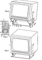
- FIG 1 designates a television playback device, which is to be held so that it can be tilted about a horizontal axis parallel to the screen. For this it sits on arcuate runners 2, 3, which are slidably mounted in corresponding arcuate recesses of a base 4.
- the skid radius is selected so that when moving the skids in the base, the housing tilts around an axis that runs approximately through the center of gravity of the housing, so that the housing is in a stable position at every incline.
- the sliding surfaces 5, 6 of the runners and that of the base consist of a material which gives a coefficient of friction which is so small on the one hand that the housing can be tilted slightly, but on the other hand is so large that its position is sufficiently stable in any position is.
- Suitable materials are e.g. B. plastic, such as self-adhesive polytetrafluoroethylene tape or felt and steel tape.
- the depressions in the base 4 and the runners 5, 6 are shaped so that the runners can be hung.
- the base 4 is designed by its triangular cross section or by triangular side cheeks so that when the housing is attached, the angle of inclination is limited and the skids can no longer fall out of the recesses.
- the runners 2, 3 are also designed so that the housing with its baseboards 7, 8 can be placed in the runners. Lateral springs 9, 10 secure it against falling out.
- the base 4 with the housing 1 sits on a plate-like foot 11 which is rotatable about a vertical axis which runs approximately through the center of the housing. The housing can therefore also be rotated about this vertical axis.
- FIG. 1 shows the new television viewing device in the position in which the screen is tilted furthest back so that the essential parts become visible
- FIG. 2 shows the viewing device with the screen tilted forward to illustrate the function of the innovation.
- the runners 2, 3 are largely covered in this position.
- FIG 3 shows the cross section of an example in which an arcuate rail 12 is mounted on the base 4, on which a slide 14, which is curved in accordance with the rail 12, is slidably mounted.
- the rail 12 is covered with a polytetrafluoroethylene layer 13.
- the foot 7 of the housing 1 sits on the slider 14.
- the rail 12 has a T-shaped cross section and is encompassed by the slider 14 in such a way that it can be suspended in the rail. If the base 4, as in the exemplary embodiment according to FIGS. 1 and 2, is given a suitable shape, the slider can no longer fall out of the rail after the housing has been put on.
- FIG. 4 An embodiment with a further guide for the inclination movement of a viewing device is shown in Figures 4 and 5.
- the housing of the television playback device is again designated.
- two sheet metal brackets 15, 16 are screwed, to each of which two pins 17, 18 and 19, 20 are fastened, which are aligned parallel to the axis of inclination. They engage in arcuate slots 21, 22 and 23, 24, which are incorporated in a base made of angled sheet 25.
- Their Bo g enradien which need not be equal, are dimensioned so that the housing may be tilted about a horizontal axis that runs approximately through the center of gravity of the housing. This is therefore rotated around the center of gravity and is stable in any inclination.
- Rollers can be placed on the pins to reduce the friction between the pins and the sheet metal base.
- the roughness of the slit edges which arises during punching by nippling with a round punch, can be used to increase the frictional torque. Even with this execution form can therefore be dispensed with a locking mechanism.
- the pins on the angle plates 15, 16 can be directed outwards. Accordingly, the angle plates lie within the base 25.
Landscapes
- Engineering & Computer Science (AREA)
- General Engineering & Computer Science (AREA)
- Mechanical Engineering (AREA)
- Multimedia (AREA)
- Signal Processing (AREA)
- Devices For Indicating Variable Information By Combining Individual Elements (AREA)
- Casings For Electric Apparatus (AREA)
Applications Claiming Priority (2)
| Application Number | Priority Date | Filing Date | Title |
|---|---|---|---|
| DE8316941U | 1983-06-09 | ||
| DE19838316941U DE8316941U1 (de) | 1983-06-09 | 1983-06-09 | Fernsehwiedergabegeraet |
Publications (2)
| Publication Number | Publication Date |
|---|---|
| EP0128511A1 true EP0128511A1 (fr) | 1984-12-19 |
| EP0128511B1 EP0128511B1 (fr) | 1987-04-08 |
Family
ID=6754124
Family Applications (1)
| Application Number | Title | Priority Date | Filing Date |
|---|---|---|---|
| EP84106424A Expired EP0128511B1 (fr) | 1983-06-09 | 1984-06-05 | Poste de reproduction de télévision |
Country Status (2)
| Country | Link |
|---|---|
| EP (1) | EP0128511B1 (fr) |
| DE (2) | DE8316941U1 (fr) |
Cited By (7)
| Publication number | Priority date | Publication date | Assignee | Title |
|---|---|---|---|---|
| US4645153A (en) * | 1985-05-23 | 1987-02-24 | Ncr Corporation | Tilt and swivel support |
| EP0276901A3 (en) * | 1987-01-30 | 1989-03-15 | Hewlett-Packard Company | Tilt and swivel mechanism |
| WO1993019323A1 (fr) * | 1992-03-16 | 1993-09-30 | Christian Tobin | Dispositif destine a fixer des objets |
| US5520361A (en) * | 1993-04-20 | 1996-05-28 | Inkel Corporation | Monitor tilting device |
| US5597218A (en) * | 1995-05-31 | 1997-01-28 | Nova Manufacturing & Assembly, Inc. | Monitor support structure for tilt angle adjustment |
| US6227518B1 (en) * | 1999-09-08 | 2001-05-08 | Compal Electronics, Inc. | Pivot base for a computer monitor |
| WO2010054831A3 (fr) * | 2008-11-14 | 2010-10-07 | Werner Kaufmann | Dispositif de support de panneau solaire |
Citations (6)
| Publication number | Priority date | Publication date | Assignee | Title |
|---|---|---|---|---|
| US2481717A (en) * | 1946-03-19 | 1949-09-13 | Blair Hosea | Tilting tripod head |
| GB902746A (en) * | 1958-06-06 | 1962-08-09 | Pye Ltd | Improvements in or relating to arrangements for mounting objects |
| EP0041804A1 (fr) * | 1980-06-05 | 1981-12-16 | Ing. C. Olivetti & C., S.p.A. | Dispositif de positionnement d'un appareil d'affichage |
| EP0042030A1 (fr) * | 1980-06-16 | 1981-12-23 | International Business Machines Corporation | Assemblage permettant un mouvement d'inclinaison et de rotation |
| US4368867A (en) * | 1981-06-29 | 1983-01-18 | Honeywell Information Systems Inc. | Tilt base for a CRT display terminal |
| EP0070337A1 (fr) * | 1981-07-20 | 1983-01-26 | International Business Machines Corporation | Support inclinable et/ou pivotant pour un dispositif de visualisation |
-
1983
- 1983-06-09 DE DE19838316941U patent/DE8316941U1/de not_active Expired
-
1984
- 1984-06-05 EP EP84106424A patent/EP0128511B1/fr not_active Expired
- 1984-06-05 DE DE8484106424T patent/DE3463093D1/de not_active Expired
Patent Citations (6)
| Publication number | Priority date | Publication date | Assignee | Title |
|---|---|---|---|---|
| US2481717A (en) * | 1946-03-19 | 1949-09-13 | Blair Hosea | Tilting tripod head |
| GB902746A (en) * | 1958-06-06 | 1962-08-09 | Pye Ltd | Improvements in or relating to arrangements for mounting objects |
| EP0041804A1 (fr) * | 1980-06-05 | 1981-12-16 | Ing. C. Olivetti & C., S.p.A. | Dispositif de positionnement d'un appareil d'affichage |
| EP0042030A1 (fr) * | 1980-06-16 | 1981-12-23 | International Business Machines Corporation | Assemblage permettant un mouvement d'inclinaison et de rotation |
| US4368867A (en) * | 1981-06-29 | 1983-01-18 | Honeywell Information Systems Inc. | Tilt base for a CRT display terminal |
| EP0070337A1 (fr) * | 1981-07-20 | 1983-01-26 | International Business Machines Corporation | Support inclinable et/ou pivotant pour un dispositif de visualisation |
Non-Patent Citations (1)
| Title |
|---|
| IBM TECHNICAL DISCLOSURE BULLETIN, Band 24, Nr. 1A, Juni 1981, Seiten 186-187, New York, US; L.H. LOWRIE u.a.: "Adjustable tilt mechanism for data-entry terminal" * |
Cited By (8)
| Publication number | Priority date | Publication date | Assignee | Title |
|---|---|---|---|---|
| US4645153A (en) * | 1985-05-23 | 1987-02-24 | Ncr Corporation | Tilt and swivel support |
| EP0276901A3 (en) * | 1987-01-30 | 1989-03-15 | Hewlett-Packard Company | Tilt and swivel mechanism |
| US4858864A (en) * | 1987-01-30 | 1989-08-22 | Hewlett-Packard Company | Tilt and swivel mechanism |
| WO1993019323A1 (fr) * | 1992-03-16 | 1993-09-30 | Christian Tobin | Dispositif destine a fixer des objets |
| US5520361A (en) * | 1993-04-20 | 1996-05-28 | Inkel Corporation | Monitor tilting device |
| US5597218A (en) * | 1995-05-31 | 1997-01-28 | Nova Manufacturing & Assembly, Inc. | Monitor support structure for tilt angle adjustment |
| US6227518B1 (en) * | 1999-09-08 | 2001-05-08 | Compal Electronics, Inc. | Pivot base for a computer monitor |
| WO2010054831A3 (fr) * | 2008-11-14 | 2010-10-07 | Werner Kaufmann | Dispositif de support de panneau solaire |
Also Published As
| Publication number | Publication date |
|---|---|
| DE8316941U1 (de) | 1983-12-08 |
| DE3463093D1 (en) | 1987-05-14 |
| EP0128511B1 (fr) | 1987-04-08 |
Similar Documents
| Publication | Publication Date | Title |
|---|---|---|
| DE69216834T2 (de) | Computerterminal | |
| DE69505688T2 (de) | Verstellbarer papierhalter | |
| EP0128511B1 (fr) | Poste de reproduction de télévision | |
| EP0248100A1 (fr) | Table pour négociant | |
| DE102005054466B4 (de) | Vorrichtung zum Halten einer Aktivtafel | |
| DE102020118079A1 (de) | Fahrbare Einrichtung zum Bewegen eines Aufnahmegeräts | |
| WO2007071765A1 (fr) | Systeme d'etagere a element support coulissant en continu dans un rail de paroi | |
| DE3325647A1 (de) | Vorrichtung zum aufnehmen einer mit einem bueroinformationsgeraet verbundenen tastatur | |
| DE2940493C2 (de) | Fernsehwiedergabegerät | |
| DE3345138A1 (de) | Demonstrationstafel | |
| EP0202446A1 (fr) | Dispositif pour l'inclinaison d'un appareil de visualisation | |
| DE3031450C2 (de) | Datensichtgerät | |
| DE3228310C2 (de) | Aufnahmevorrichtung für ein Datensichtgerät | |
| AT313U1 (de) | Geraetekonsole fuer arbeits- und kommandopulte oder schreibtische | |
| DE3541982A1 (de) | Vorrichtung zum tragen von geraeten auf einer arbeitsflaeche | |
| DE8403569U1 (de) | Arbeitstisch fuer micro-computer | |
| EP0442317A2 (fr) | Table ou plan de travail, en particulier planche à écrire | |
| AT404223B (de) | Vorrichtung zur darstellung von grossen beschriebenen papierbögen | |
| DE951699C (de) | Halter fuer Filter in Kinoprojektionsanlagen | |
| DE8511010U1 (de) | Neigungsvorrichtung für Sichtgeräte | |
| DE3016353C2 (de) | Möbel mit verstellbarer Tischplatte | |
| DE3616941A1 (de) | Hilfsgeraet fuer arbeitsplatten | |
| DE29821666U1 (de) | Mehrzweck-Büroarbeitstisch | |
| EP3835642A1 (fr) | Dispositif de support d'appareils mobiles sur le tableau de bord d'un véhicule ferroviaire | |
| DE9421577U1 (de) | Bürotisch |
Legal Events
| Date | Code | Title | Description |
|---|---|---|---|
| PUAI | Public reference made under article 153(3) epc to a published international application that has entered the european phase |
Free format text: ORIGINAL CODE: 0009012 |
|
| AK | Designated contracting states |
Designated state(s): DE FR NL |
|
| 17P | Request for examination filed |
Effective date: 19841221 |
|
| 17Q | First examination report despatched |
Effective date: 19860528 |
|
| GRAA | (expected) grant |
Free format text: ORIGINAL CODE: 0009210 |
|
| AK | Designated contracting states |
Kind code of ref document: B1 Designated state(s): DE FR NL |
|
| REF | Corresponds to: |
Ref document number: 3463093 Country of ref document: DE Date of ref document: 19870514 |
|
| ET | Fr: translation filed | ||
| PLBE | No opposition filed within time limit |
Free format text: ORIGINAL CODE: 0009261 |
|
| STAA | Information on the status of an ep patent application or granted ep patent |
Free format text: STATUS: NO OPPOSITION FILED WITHIN TIME LIMIT |
|
| 26N | No opposition filed | ||
| PGFP | Annual fee paid to national office [announced via postgrant information from national office to epo] |
Ref country code: NL Payment date: 19900630 Year of fee payment: 7 |
|
| PG25 | Lapsed in a contracting state [announced via postgrant information from national office to epo] |
Ref country code: NL Effective date: 19920101 |
|
| NLV4 | Nl: lapsed or anulled due to non-payment of the annual fee | ||
| PGFP | Annual fee paid to national office [announced via postgrant information from national office to epo] |
Ref country code: FR Payment date: 19930618 Year of fee payment: 10 |
|
| PG25 | Lapsed in a contracting state [announced via postgrant information from national office to epo] |
Ref country code: FR Effective date: 19950228 |
|
| REG | Reference to a national code |
Ref country code: FR Ref legal event code: ST |
|
| PGFP | Annual fee paid to national office [announced via postgrant information from national office to epo] |
Ref country code: DE Payment date: 19950818 Year of fee payment: 12 |
|
| PG25 | Lapsed in a contracting state [announced via postgrant information from national office to epo] |
Ref country code: DE Effective date: 19970301 |