EP0128624A2 - Procédé et dispositif pour la synchronisation d'un système de transmission de données - Google Patents
Procédé et dispositif pour la synchronisation d'un système de transmission de données Download PDFInfo
- Publication number
- EP0128624A2 EP0128624A2 EP84200816A EP84200816A EP0128624A2 EP 0128624 A2 EP0128624 A2 EP 0128624A2 EP 84200816 A EP84200816 A EP 84200816A EP 84200816 A EP84200816 A EP 84200816A EP 0128624 A2 EP0128624 A2 EP 0128624A2
- Authority
- EP
- European Patent Office
- Prior art keywords
- words
- code
- word
- bit
- protective
- Prior art date
- Legal status (The legal status is an assumption and is not a legal conclusion. Google has not performed a legal analysis and makes no representation as to the accuracy of the status listed.)
- Withdrawn
Links
- 230000005540 biological transmission Effects 0.000 title claims abstract description 35
- 238000000034 method Methods 0.000 title claims description 16
- 238000012360 testing method Methods 0.000 claims abstract description 29
- 230000001681 protective effect Effects 0.000 claims abstract description 26
- 230000009897 systematic effect Effects 0.000 claims description 4
- 230000001360 synchronised effect Effects 0.000 claims description 3
- 238000011156 evaluation Methods 0.000 description 3
- 238000012937 correction Methods 0.000 description 2
- 230000006870 function Effects 0.000 description 2
- 239000011159 matrix material Substances 0.000 description 2
- 241001136792 Alle Species 0.000 description 1
- 238000010586 diagram Methods 0.000 description 1
- 238000003780 insertion Methods 0.000 description 1
- 230000037431 insertion Effects 0.000 description 1
- 208000011580 syndromic disease Diseases 0.000 description 1
Images


Classifications
-
- H—ELECTRICITY
- H04—ELECTRIC COMMUNICATION TECHNIQUE
- H04L—TRANSMISSION OF DIGITAL INFORMATION, e.g. TELEGRAPHIC COMMUNICATION
- H04L7/00—Arrangements for synchronising receiver with transmitter
- H04L7/04—Speed or phase control by synchronisation signals
- H04L7/048—Speed or phase control by synchronisation signals using the properties of error detecting or error correcting codes, e.g. parity as synchronisation signal
-
- H—ELECTRICITY
- H04—ELECTRIC COMMUNICATION TECHNIQUE
- H04L—TRANSMISSION OF DIGITAL INFORMATION, e.g. TELEGRAPHIC COMMUNICATION
- H04L1/00—Arrangements for detecting or preventing errors in the information received
- H04L1/004—Arrangements for detecting or preventing errors in the information received by using forward error control
- H04L1/0056—Systems characterized by the type of code used
- H04L1/0057—Block codes
Definitions
- the invention relates to a method and a circuit arrangement for synchronization in a data transmission system according to the preambles of claims 1 and 6.
- messages can be exchanged between them via transmission channels.
- These messages can have a word structure and can consist, for example, of string words of a linear block code.
- a block code is a code with code words of the same length, in which a sequence of symbols (data) or words of a source to be coded is divided into blocks of the same length.
- a code word is assigned to each of the symbols or words of the data source.
- each linear combination of code words again results in a code word.
- code words are strung together and transmitted in a continuous sequence via the transmission channel, the sequence must be divided into code words at the receiving end, i.e. word synchronization. If word synchronization is lost, combinations of code elements which come from two successive code words are fed to a decoder. Decoding is not possible if no code word from the code word pool can be assigned.
- the individual code words are interleaved bit by bit before transmission.
- bit by bit interleaving a row each of the first bit of the code words, then so on joined the second bit of the code words and to the last bit of the code words of the message (as cod, "Performance and Limits of Coding for SimpleTime Varyin g Channels", 1980 , International Zurich Seminar on Digital Communications, Proceedings, IEEE Catalog No. 80 CH 1521-4, left column from page G 1.1).
- the invention is based on the observation that incorrect synchronization in the case of bit-wise interleaved code words results in an interchange in the order of the deinterleaved code words at the receiver.
- the invention is based on the object of specifying a method and circuit arrangement for word synchronization, with which exchanges in the sequence of code words of a message can be detected.
- code words of a linear block code interleaved bit by bit and via a faulty transmission channel can be exchanged for the original order of the code words of a message.
- By linking code words or words with their protective words or test words characterizing their position within the message a reversal in the order can be reliably detected.
- the choice of protective words or test words is easy to make.
- code words are transmitted over a disturbed transmission channel, a bundle of errors can occur accidentally in a code word. Due to the bit-wise interleaving of the code words, the bundle of errors is distributed over different code words. The word error probability and the residual error probability are lower compared to the blockwise transmission of code words.
- the length of the protective or test words can be limited to the test parts of the code words or words.
- the circuit complexity on the receiving and transmitting sides for implementing the method can be reduced in a simple manner.
- test words and protective words are stored on the receiving and transmitting sides.
- the amount of memory can be reduced by half if the protective words are chosen equal to the test words.
- a reduction in the amount of memory can be achieved if the Protective and test words can be selected as code words of a linear code, the generator matrix being stored, for example.
- a data source 1 is connected to a data sink 3 via a transmission channel 2.
- An encoder 4, an addition circuit 6 and a first device 8 for bitwise interleaving of modified code words c ' L are arranged on the transmission side.
- Subtraction circuit 7 and a decoder 5 are provided.
- the symbols (data) or words of the data source 1 are assigned code words c L according to a coding rule.
- a protection word w L characterizing its position within a message M is linked to each code word c L.
- the protection words w L are stored in a memory 10.
- the modified code words c ' L thus formed are interleaved bit by bit, transmitted and de-interleaved on the receiving side. After deinterleaving, a word ⁇ K occurring on the receiving side is linked in the subtraction circuit 7 with a check word w K which identifies its position within the message M.
- the test words w K are stored in a memory 11.
- the code word c K at the output of the subtraction circuit 7 is equal to the code word c L on the transmission side.
- the code word c K is converted into a word or data in the decoder 5 and supplied to the data sink 3 for message evaluation. A simulated block synchronization can lead to an incorrect message evaluation in data sink 3.
- radio subscriber numbers are transmitted as messages via a transmission channel 2 between a mobile subscriber station (data source 1) and a fixed radio station (data sink 3).
- the message M comprises, for example, ten code words and in the reverse direction eight code words.
- An incorrect message evaluation can, for example, result in incorrectly charging call charges.
- the table 2 shows in table form the bitwise nesting of the modified code words c 'and the bitwise deinterleaving of the words der K.
- the table shows a message M consisting of sixteen code elements, to which four code words (c ' L , c K ) with a number of digits four are assigned. The sixteen digits of the bit sequence of the message M sent and received are indicated in the head of the table.
- the modified code words c ' L and the words c K are arranged according to their order in the message M.
- the order of the words sent (ci, c '2, C' 3, c4) v e r - exchanged, that is, the code words c K be in a different order (c3, c4, c 1, c ' 2 ) received.
- the indexing of the code elements within the table is intended to clarify that this code element is the code element arranged at the fourth position of the second modified code word c' L.
- the crosses at the fifteenth and sixteenth bit positions within the received message M indicate that these code elements are code elements that are not code elements of the transmitted ones Message M belong.
- a shift by two bit positions causes the words ⁇ K to be swapped in their order by two.
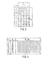
- FIG. 3 shows the sequence of the received words c K as a function of a shift by f bit positions.
- the message M should comprise four code words c L or four words c K.
- the shift in the left column of the table is shown by up to three bit positions, the sign indicating the direction of shift.
- the word c K is received too late in comparison to the transmitted order of the code words c L (or modified code words c ' L ) or received too early, as indicated by the positive sign.
- the received words c K are cyclically interchanged with the transmitted code words c L and there are additional shifts in the last f or first f words c K.
- words c K in which this additional shift occurs, are indicated by an asterisk which is uppermost in number.
- the probability that a message M is incorrectly evaluated due to incorrect synchronization is very high, especially when shifted by a few bit positions.
- the bit shift in each of the words c K can result in a binary pattern which is a code word from the code word stock of the code.
- each code word c L is based on the linking rule linked with the protection word w L , a bit-wise mod-2 addition preferably being used as the linking rule.
- the received word ⁇ K After bit-by-bit interleaving, transmission and deinterleaving, the received word ⁇ K , according to the linking rule preferably by mod-2 addition, the test word w K linked. On the receiving side, a keyword w KL is created , which according to the linking rule is formed.
- the code violation caused on the transmission side by the addition of the protective words w L is then canceled on the receiving side by adding the test word w K again .
- the protective or test words w L or w K must be selected such that the Keywords w KL are in a subclass which is not used for decoding.
- the secondary class can be determined, for example, by forming the syndrome.
- bit patterns are chosen so that when the protective words w L or test words W K are linked, a keyword w KL is created which has a higher Hamming distance than the number e of errors corrected for each code word.
- the bit patterns of protective word w L or test word w K are to be selected such that the resulting keyword w KL for K # L is not a code word from the code word set. It can be shown that the bit pattern sought must be elements from different subclasses N t . The aim is to choose the bit patterns sought so that the resulting keywords w KL for K # L are in subclasses that are not used for decoding.
- bit patterns of w L and w K do not match.
- further code violations are added by the addition of the bit pattern of test word w K on the receiving side.
- the sum of the corrupted binary digits (code elements) in word c K is greater than the number e of correctable errors.
- Fig. 5 is for the linear, systematic (16.8.5).
- Block code with error correction 2 (e 2) specified by the matrix S w chlüsselwörtern KL, which is obtained by linking the bit pattern of protected words w K and check words w L in FIG. 4.
- a quadruple 25, 44, 138, 201 can be determined as the bit pattern, which spans a subspace with sixteen bit patterns. Ten are selected from these sixteen bit patterns, which are given in the table of FIG. 4. 5 shows all possible combinations of these ten bit patterns.
- the keywords w KL with the decimal representation 111 and 118 that arise during the linking are elements of a secondary class N t for a code with a minimum distance equal to two.
- the keyword w KL is linked with the decimal number 25 and with a check word W L with the decimal number 111.
- the keyword w KL with the decimal number 118 (code word) resulting from a bit shift of seven digits contains two errors and can therefore be corrected for errors.
- Keywords w KL of such subclasses N t are shown in FIG. 5 with a minus sign Mistake. Such keywords w KL only occur with a shift by more than seven bit positions, the probability of such a shift being very low.
- the method according to the invention can thus reduce the probability of undetected incorrect synchronization. In this way, falsification of messages (messages M at a higher protocol level) caused by incorrect synchronization can be avoided.
Landscapes
- Engineering & Computer Science (AREA)
- Computer Networks & Wireless Communication (AREA)
- Signal Processing (AREA)
- Detection And Prevention Of Errors In Transmission (AREA)
- Synchronisation In Digital Transmission Systems (AREA)
- Communication Control (AREA)
Applications Claiming Priority (2)
| Application Number | Priority Date | Filing Date | Title |
|---|---|---|---|
| DE19833320948 DE3320948A1 (de) | 1983-06-10 | 1983-06-10 | Verfahren zur synchronisation in einem datenuebertragungssystem bei verwendung eines linearen blockcodes |
| DE3320948 | 1983-06-10 |
Publications (2)
| Publication Number | Publication Date |
|---|---|
| EP0128624A2 true EP0128624A2 (fr) | 1984-12-19 |
| EP0128624A3 EP0128624A3 (fr) | 1987-12-02 |
Family
ID=6201114
Family Applications (1)
| Application Number | Title | Priority Date | Filing Date |
|---|---|---|---|
| EP84200816A Withdrawn EP0128624A3 (fr) | 1983-06-10 | 1984-06-08 | Procédé et dispositif pour la synchronisation d'un système de transmission de données |
Country Status (8)
| Country | Link |
|---|---|
| US (1) | US4635262A (fr) |
| EP (1) | EP0128624A3 (fr) |
| JP (1) | JPS6041833A (fr) |
| AU (1) | AU569443B2 (fr) |
| CA (1) | CA1230396A (fr) |
| DE (1) | DE3320948A1 (fr) |
| DK (1) | DK281084A (fr) |
| ZA (1) | ZA844404B (fr) |
Cited By (2)
| Publication number | Priority date | Publication date | Assignee | Title |
|---|---|---|---|---|
| FR2608871A1 (fr) * | 1986-12-18 | 1988-06-24 | Cit Alcatel | Procede de multiplexage et de demultiplexage temporel de trains numeriques synchrones |
| EP0501857A1 (fr) * | 1991-02-22 | 1992-09-02 | Institut Francais Du Petrole | Méthode et dispositif de transmission sismique à taux d'erreur très faibles |
Families Citing this family (7)
| Publication number | Priority date | Publication date | Assignee | Title |
|---|---|---|---|---|
| EP0265488A1 (fr) * | 1986-03-28 | 1988-05-04 | Ampex Corporation | Transmission de donnees numeriques avec detection d'erreurs notamment dans des blocs de mots |
| US5280484A (en) * | 1989-07-08 | 1994-01-18 | Alcatel N.V. | Time-division multiplex communication system with a synchronizing circuit at the receiving end which responds to the coding of words inserted in the transmitted information |
| US5461631A (en) * | 1992-12-15 | 1995-10-24 | International Business Machines Corporation | Method for bit resynchronization of code-constrained sequences |
| DE4408163A1 (de) * | 1994-03-11 | 1995-09-14 | Bosch Gmbh Robert | Verfahren zum Übertragen von Daten |
| US5727004A (en) * | 1995-03-14 | 1998-03-10 | Adaptive Networks, Inc. | Method and apparatus for data encoding and communication over noisy media |
| US7681110B2 (en) * | 2006-08-30 | 2010-03-16 | Microsoft Corporation | Decoding technique for linear block codes |
| US8103934B2 (en) | 2007-12-21 | 2012-01-24 | Honeywell International Inc. | High speed memory error detection and correction using interleaved (8,4) LBCs |
Family Cites Families (9)
| Publication number | Priority date | Publication date | Assignee | Title |
|---|---|---|---|---|
| NL267314A (fr) * | 1960-03-02 | |||
| BE656364A (fr) * | 1963-11-29 | |||
| JPS5292413A (en) * | 1976-01-30 | 1977-08-03 | Toshiba Corp | Data transfer system |
| JPS5380105A (en) * | 1976-12-24 | 1978-07-15 | Sony Corp | Digital signal transmission method |
| US4271520A (en) * | 1979-06-25 | 1981-06-02 | Motorola, Inc. | Synchronizing technique for an error correcting digital transmission system |
| US4312070A (en) * | 1979-12-07 | 1982-01-19 | Motorola, Inc. | Digital encoder-decoder |
| US4468752A (en) * | 1981-09-21 | 1984-08-28 | Tandy Corporation | Data synchronization apparatus |
| US4466099A (en) * | 1981-12-20 | 1984-08-14 | International Business Machines Corp. | Information system using error syndrome for special control |
| US4541091A (en) * | 1982-06-11 | 1985-09-10 | Hitachi, Ltd. | Code error detection and correction method and apparatus |
-
1983
- 1983-06-10 DE DE19833320948 patent/DE3320948A1/de not_active Withdrawn
-
1984
- 1984-06-07 DK DK281084A patent/DK281084A/da not_active Application Discontinuation
- 1984-06-07 CA CA000456064A patent/CA1230396A/fr not_active Expired
- 1984-06-08 EP EP84200816A patent/EP0128624A3/fr not_active Withdrawn
- 1984-06-08 AU AU29229/84A patent/AU569443B2/en not_active Ceased
- 1984-06-09 JP JP59117481A patent/JPS6041833A/ja active Pending
- 1984-06-11 US US06/618,976 patent/US4635262A/en not_active Expired - Fee Related
- 1984-06-11 ZA ZA844404A patent/ZA844404B/xx unknown
Cited By (2)
| Publication number | Priority date | Publication date | Assignee | Title |
|---|---|---|---|---|
| FR2608871A1 (fr) * | 1986-12-18 | 1988-06-24 | Cit Alcatel | Procede de multiplexage et de demultiplexage temporel de trains numeriques synchrones |
| EP0501857A1 (fr) * | 1991-02-22 | 1992-09-02 | Institut Francais Du Petrole | Méthode et dispositif de transmission sismique à taux d'erreur très faibles |
Also Published As
| Publication number | Publication date |
|---|---|
| JPS6041833A (ja) | 1985-03-05 |
| CA1230396A (fr) | 1987-12-15 |
| EP0128624A3 (fr) | 1987-12-02 |
| ZA844404B (en) | 1986-01-29 |
| DK281084D0 (da) | 1984-06-07 |
| DK281084A (da) | 1984-12-11 |
| AU2922984A (en) | 1984-12-13 |
| US4635262A (en) | 1987-01-06 |
| DE3320948A1 (de) | 1984-12-13 |
| AU569443B2 (en) | 1988-01-28 |
Similar Documents
| Publication | Publication Date | Title |
|---|---|---|
| DE69020671T2 (de) | Drahtloses Signalübertragungssystem mit wahlfreiem Zugriff. | |
| DE69425400T2 (de) | Verfahren und Vorrichtung zur Verschachtelung einer Folge von Datenelementen | |
| DE3119669C2 (fr) | ||
| DE2914515A1 (de) | Verfahren und vorrichtung fuer ein wirksames fehlerentdeckungs- und korrektursystem | |
| DE2260850A1 (de) | Fehlerkorrektursystem | |
| DE2942825A1 (de) | Verfahren und vorrichtung zur verarbeitung sequentiell uebertragender digitaler informationsworte | |
| DE4233089A1 (de) | Digitalfunkempfaenger | |
| DE2320422A1 (de) | Verfahren zur fehlererkennung | |
| DE3027579C2 (fr) | ||
| EP0219917B1 (fr) | Dispositif de commutation avec correction de fautes | |
| DE2460263A1 (de) | Schaltungsanordnung zum korrigieren des schlupffehlers in datenuebertragungssystemen unter verwendung von zyklischen codes | |
| EP0128624A2 (fr) | Procédé et dispositif pour la synchronisation d'un système de transmission de données | |
| EP0003480B1 (fr) | Dispositif pour convertir des informations binaires à l'aide de bits de contrôle | |
| DE2554125A1 (de) | Verfahren und vorrichtung zur rahmenbildung von multiplex-impulssignalen | |
| DE2053836C3 (de) | Anordnung zur Korrektur von Fehlerbündeln in binär codierten Datengruppen | |
| DE60022941T2 (de) | Verfahren und Verfahren zur Übertragung von codierten Daten mit variabler Länge in einer Umgebung mit geringem Störabstand | |
| DE3750456T2 (de) | Fehlerkorrigierender, bitserieller Dekodierer. | |
| DE19607710A1 (de) | Verfahren und Vorrichtung zur Korrektur von Fehlern unter Verwendung mehrfacher Schätzungen | |
| DE69327212T2 (de) | System für Übertragung von Informationsbitfolgen | |
| DE1168677B (de) | System zur Fehlerermittlung und Fehlerkorrektur | |
| DE2827615B2 (de) | Verfahren und Schaltungsanordnung zum Synchronisieren zwei oder mehrerer räumlich voneinander entfernter digital arbeitender nachrichtentechnischer Einrichtungen | |
| DE69229397T2 (de) | Verfahren zur kodierung und dekodierung einer digitalen nachricht | |
| DE68923736T2 (de) | Dekoder für Hamming kodierte Daten. | |
| DE1944963A1 (de) | Stoerungsgesichertes UEbertragungssystem | |
| DE2756923C2 (de) | Anordnung zur Daten- und Nachrichtenübertragung |
Legal Events
| Date | Code | Title | Description |
|---|---|---|---|
| PUAI | Public reference made under article 153(3) epc to a published international application that has entered the european phase |
Free format text: ORIGINAL CODE: 0009012 |
|
| AK | Designated contracting states |
Designated state(s): AT BE CH DE FR GB IT LI SE |
|
| RAP1 | Party data changed (applicant data changed or rights of an application transferred) |
Owner name: N.V. PHILIPS' GLOEILAMPENFABRIEKEN Owner name: PHILIPS PATENTVERWALTUNG GMBH |
|
| PUAL | Search report despatched |
Free format text: ORIGINAL CODE: 0009013 |
|
| AK | Designated contracting states |
Kind code of ref document: A3 Designated state(s): AT BE CH DE FR GB IT LI SE |
|
| 17P | Request for examination filed |
Effective date: 19880520 |
|
| 17Q | First examination report despatched |
Effective date: 19890727 |
|
| STAA | Information on the status of an ep patent application or granted ep patent |
Free format text: STATUS: THE APPLICATION HAS BEEN WITHDRAWN |
|
| 18W | Application withdrawn |
Withdrawal date: 19891123 |
|
| R18W | Application withdrawn (corrected) |
Effective date: 19891123 |
|
| RIN1 | Information on inventor provided before grant (corrected) |
Inventor name: KITTEL, LUDWIG, DR. |