EP0128960B1 - Thermomagnetisches optisches aufzeichnungs-/wiedergabeverfahren - Google Patents
Thermomagnetisches optisches aufzeichnungs-/wiedergabeverfahren Download PDFInfo
- Publication number
- EP0128960B1 EP0128960B1 EP84900112A EP84900112A EP0128960B1 EP 0128960 B1 EP0128960 B1 EP 0128960B1 EP 84900112 A EP84900112 A EP 84900112A EP 84900112 A EP84900112 A EP 84900112A EP 0128960 B1 EP0128960 B1 EP 0128960B1
- Authority
- EP
- European Patent Office
- Prior art keywords
- layers
- layer
- soft magnetic
- recording system
- magnetic material
- Prior art date
- Legal status (The legal status is an assumption and is not a legal conclusion. Google has not performed a legal analysis and makes no representation as to the accuracy of the status listed.)
- Expired
Links
Images



Classifications
-
- G—PHYSICS
- G11—INFORMATION STORAGE
- G11B—INFORMATION STORAGE BASED ON RELATIVE MOVEMENT BETWEEN RECORD CARRIER AND TRANSDUCER
- G11B11/00—Recording on or reproducing from the same record carrier wherein for these two operations the methods are covered by different main groups of groups G11B3/00 - G11B7/00 or by different subgroups of group G11B9/00; Record carriers therefor
- G11B11/10—Recording on or reproducing from the same record carrier wherein for these two operations the methods are covered by different main groups of groups G11B3/00 - G11B7/00 or by different subgroups of group G11B9/00; Record carriers therefor using recording by magnetic means or other means for magnetisation or demagnetisation of a record carrier, e.g. light induced spin magnetisation; Demagnetisation by thermal or stress means in the presence or not of an orienting magnetic field
- G11B11/105—Recording on or reproducing from the same record carrier wherein for these two operations the methods are covered by different main groups of groups G11B3/00 - G11B7/00 or by different subgroups of group G11B9/00; Record carriers therefor using recording by magnetic means or other means for magnetisation or demagnetisation of a record carrier, e.g. light induced spin magnetisation; Demagnetisation by thermal or stress means in the presence or not of an orienting magnetic field using a beam of light or a magnetic field for recording by change of magnetisation and a beam of light for reproducing, i.e. magneto-optical, e.g. light-induced thermomagnetic recording, spin magnetisation recording, Kerr or Faraday effect reproducing
- G11B11/10502—Recording on or reproducing from the same record carrier wherein for these two operations the methods are covered by different main groups of groups G11B3/00 - G11B7/00 or by different subgroups of group G11B9/00; Record carriers therefor using recording by magnetic means or other means for magnetisation or demagnetisation of a record carrier, e.g. light induced spin magnetisation; Demagnetisation by thermal or stress means in the presence or not of an orienting magnetic field using a beam of light or a magnetic field for recording by change of magnetisation and a beam of light for reproducing, i.e. magneto-optical, e.g. light-induced thermomagnetic recording, spin magnetisation recording, Kerr or Faraday effect reproducing characterised by the transducing operation to be executed
- G11B11/10504—Recording
- G11B11/10506—Recording by modulating only the light beam of the transducer
-
- G—PHYSICS
- G02—OPTICS
- G02F—OPTICAL DEVICES OR ARRANGEMENTS FOR THE CONTROL OF LIGHT BY MODIFICATION OF THE OPTICAL PROPERTIES OF THE MEDIA OF THE ELEMENTS INVOLVED THEREIN; NON-LINEAR OPTICS; FREQUENCY-CHANGING OF LIGHT; OPTICAL LOGIC ELEMENTS; OPTICAL ANALOGUE/DIGITAL CONVERTERS
- G02F3/00—Optical logic elements; Optical bistable devices
-
- G—PHYSICS
- G11—INFORMATION STORAGE
- G11B—INFORMATION STORAGE BASED ON RELATIVE MOVEMENT BETWEEN RECORD CARRIER AND TRANSDUCER
- G11B11/00—Recording on or reproducing from the same record carrier wherein for these two operations the methods are covered by different main groups of groups G11B3/00 - G11B7/00 or by different subgroups of group G11B9/00; Record carriers therefor
- G11B11/10—Recording on or reproducing from the same record carrier wherein for these two operations the methods are covered by different main groups of groups G11B3/00 - G11B7/00 or by different subgroups of group G11B9/00; Record carriers therefor using recording by magnetic means or other means for magnetisation or demagnetisation of a record carrier, e.g. light induced spin magnetisation; Demagnetisation by thermal or stress means in the presence or not of an orienting magnetic field
- G11B11/105—Recording on or reproducing from the same record carrier wherein for these two operations the methods are covered by different main groups of groups G11B3/00 - G11B7/00 or by different subgroups of group G11B9/00; Record carriers therefor using recording by magnetic means or other means for magnetisation or demagnetisation of a record carrier, e.g. light induced spin magnetisation; Demagnetisation by thermal or stress means in the presence or not of an orienting magnetic field using a beam of light or a magnetic field for recording by change of magnetisation and a beam of light for reproducing, i.e. magneto-optical, e.g. light-induced thermomagnetic recording, spin magnetisation recording, Kerr or Faraday effect reproducing
- G11B11/10502—Recording on or reproducing from the same record carrier wherein for these two operations the methods are covered by different main groups of groups G11B3/00 - G11B7/00 or by different subgroups of group G11B9/00; Record carriers therefor using recording by magnetic means or other means for magnetisation or demagnetisation of a record carrier, e.g. light induced spin magnetisation; Demagnetisation by thermal or stress means in the presence or not of an orienting magnetic field using a beam of light or a magnetic field for recording by change of magnetisation and a beam of light for reproducing, i.e. magneto-optical, e.g. light-induced thermomagnetic recording, spin magnetisation recording, Kerr or Faraday effect reproducing characterised by the transducing operation to be executed
- G11B11/10515—Reproducing
-
- G—PHYSICS
- G11—INFORMATION STORAGE
- G11B—INFORMATION STORAGE BASED ON RELATIVE MOVEMENT BETWEEN RECORD CARRIER AND TRANSDUCER
- G11B11/00—Recording on or reproducing from the same record carrier wherein for these two operations the methods are covered by different main groups of groups G11B3/00 - G11B7/00 or by different subgroups of group G11B9/00; Record carriers therefor
- G11B11/10—Recording on or reproducing from the same record carrier wherein for these two operations the methods are covered by different main groups of groups G11B3/00 - G11B7/00 or by different subgroups of group G11B9/00; Record carriers therefor using recording by magnetic means or other means for magnetisation or demagnetisation of a record carrier, e.g. light induced spin magnetisation; Demagnetisation by thermal or stress means in the presence or not of an orienting magnetic field
- G11B11/105—Recording on or reproducing from the same record carrier wherein for these two operations the methods are covered by different main groups of groups G11B3/00 - G11B7/00 or by different subgroups of group G11B9/00; Record carriers therefor using recording by magnetic means or other means for magnetisation or demagnetisation of a record carrier, e.g. light induced spin magnetisation; Demagnetisation by thermal or stress means in the presence or not of an orienting magnetic field using a beam of light or a magnetic field for recording by change of magnetisation and a beam of light for reproducing, i.e. magneto-optical, e.g. light-induced thermomagnetic recording, spin magnetisation recording, Kerr or Faraday effect reproducing
- G11B11/10532—Heads
- G11B11/10534—Heads for recording by magnetising, demagnetising or transfer of magnetisation, by radiation, e.g. for thermomagnetic recording
- G11B11/10536—Heads for recording by magnetising, demagnetising or transfer of magnetisation, by radiation, e.g. for thermomagnetic recording using thermic beams, e.g. lasers
-
- G—PHYSICS
- G11—INFORMATION STORAGE
- G11B—INFORMATION STORAGE BASED ON RELATIVE MOVEMENT BETWEEN RECORD CARRIER AND TRANSDUCER
- G11B11/00—Recording on or reproducing from the same record carrier wherein for these two operations the methods are covered by different main groups of groups G11B3/00 - G11B7/00 or by different subgroups of group G11B9/00; Record carriers therefor
- G11B11/10—Recording on or reproducing from the same record carrier wherein for these two operations the methods are covered by different main groups of groups G11B3/00 - G11B7/00 or by different subgroups of group G11B9/00; Record carriers therefor using recording by magnetic means or other means for magnetisation or demagnetisation of a record carrier, e.g. light induced spin magnetisation; Demagnetisation by thermal or stress means in the presence or not of an orienting magnetic field
- G11B11/105—Recording on or reproducing from the same record carrier wherein for these two operations the methods are covered by different main groups of groups G11B3/00 - G11B7/00 or by different subgroups of group G11B9/00; Record carriers therefor using recording by magnetic means or other means for magnetisation or demagnetisation of a record carrier, e.g. light induced spin magnetisation; Demagnetisation by thermal or stress means in the presence or not of an orienting magnetic field using a beam of light or a magnetic field for recording by change of magnetisation and a beam of light for reproducing, i.e. magneto-optical, e.g. light-induced thermomagnetic recording, spin magnetisation recording, Kerr or Faraday effect reproducing
- G11B11/10582—Record carriers characterised by the selection of the material or by the structure or form
- G11B11/10586—Record carriers characterised by the selection of the material or by the structure or form characterised by the selection of the material
- G11B11/10589—Details
Definitions
- thermomagnetic recording systems and to thermomagnetic recording and reproducing systems. Such systems can be used in optical magnetic disc apparatus or the like.
- thermomagnetic recording system which uses a layer of soft magnetic material having an easy axis of magnetisation normal to the layer surface, on which thermomagnetic recording is performed by irradiating laser light thereon.
- the layer of soft magnetic material is, for example, a YSmCaFeGe-series garnet such as (YSmCa) 3 (FeGe) 6 0 12 or the like, having uniaxial magnetic anisotropy which is strong in the direction normal to the layer surface and an easy axis of magnetisation normal to the layer surface.
- the layer of soft magnetic material having an easy axis of magnetisation normal to the layer surface is required to have such a soft magnetic property that, when the layer is used as a magnetic recording medium, the diameter of information bits to be written therein is practically determined only by a bias magnetic field, and the coercive force thereof is desired to be less than about 240 A/m (3 Oe), preferably about 80 A/m (1 Oe) or below.
- the layer is formed by growing it on a crystalline substrate of rare-earth gallium garnet, such as non-magnetic gadolinium gallium garnet (GGG), by liquid phase epitaxial (LPE) growth of YSmCaFeGe-series garnet crystal or the like.
- the writing of information on the layer is carried out by first applying a bias magnetic field of a predetermined strength to the layer so as to make the layer magnetised to have a single magnetic domain over the whole visual field thereof and a direction of magnetisation oriented perpendicularly to the layer surface. Then, under this state, when an optical pulse is incident on the layer surface and focused thereon, the writing of information bits on the layer can be performed.
- the bits thus written are cylindrical magnetic domains each having a predetermined diameter and a direction of magnetisation which is of opposite direction to the applied bias magnetic field.
- the strength of the bias magnetic field applied to the layer of soft magnetic material so as to produce a single magnetic domain therein over the whole visual field thereof is selected to be in a range from the run-out magnetic field to the collapse magnetic field of the material, for example, between 4536 A/m (57 Oe) and 5809 A/ m (73 Oe) for the above-mentioned LPE layer of (YSmCa) 3 (FeGe) 5 0 1 ,.
- the bias magnetic field applying means may be a small solenoid coil, rubber magnet or the like.
- the reading out of information recorded on the magnetised layer is carried out by irradiating the record medium with light, for example laser light that is linearly polarised by a polariser.
- light for example laser light that is linearly polarised by a polariser.
- the linearly polarised light passes through the magnetised layer, it is subjected to rotation of its plane of polarisation by the Faraday effect.
- this rotated light is applied through an analyser to a photo-detecting means, an output corresponding to the information bits is produced therefrom and hence reading out of the information is performed.
- thermomagnetic recording system however, the garnet film used as a recording layer presents transmissivity to light of a wavelength longer than about 530 nm, whereby light of such a long wavelength can almost not be absorbed by a film having a thickness of 10 micrometres or less. Therefore, in this thermomagnetic recording system, an Argon laser having a wavelength of, for example, 488 nm is used for the light source.
- thermomagnetic recording system comprising: a recording medium formed by a flexible plastic substrate having thereon a layer of hard magnetic material, a gas layer, a dielectric multi-layer film, a transparent magnetic film, and a transparent substrate; means for applying a magnetic film to the layer of hard magnetic material; and means for irradiating the recording medium with laser light.
- Information can be written on the layer of hard magnetic material by irradiating the layer with laser light at a first wavelength (633 nm).
- the light of the first wavelength is directed to the layer of hard magnetic material via the transparent substrate, the transparent magnetic film and the dielectric multi-layer film (which can transmit light of the first wavelength) and heats the layer of hard magnetic material.
- the information thereby recorded on the layer of hard magnetic material is transferred to the transparent magnetic film and can be read out by using laser light having a second wavelength (514 nm) by using the Faraday effect.
- the reading light is reflected by the dielectric multi-layer film, since that film has a high reflectivity with respect to light at the second wavelength and thus acts as a mirror to it.
- thermomagnetic recording system comprising:
- Embodiments of the inventions described in detail below enable even a semiconductor laser having a long wavelength, which could not be absorbed by a magnetised film, to be used to record information.
- the embodiments of the invention are capable, as described below, of increasing recording density and of logical calculation.
- Figure 1 or 2 show respective recording media 5, in each of which at least a first layer 1 of soft magnetic material having an easy axis of magnetisation normal to the layer surface, a transparent non-magnetic intermediate layer 2, a second layer 3 of soft magnetic material having an easy axis of magnetisation normal to the layer surface and a metal or semi-metal film 4 adjacent to the second layer of soft magnetic material are superposed on one another so as thereby to form the recording medium 5.
- the layers 1, 2 and 3 and the film 4 are disposed as shown on a substrate 6, whereas in the recording medium 5 shown in Figure 2 the intermediate layer 2 and the substrate 6 are one and the same element.
- a bias magnetic field is applied to the first and second magnetic layers 1 and 3 such that they are each magnetised to have a single magnetic domain and a direction of magnetisation oriented perpendicularly to the layer surfaces over their whole surfaces. If, under this condition, a light pulse having a first wavelength, for example a relatively short wavelength, absorbed with a relatively high optical absorptance in the magnetic layer, is made incident on the single magnetic domain of the first magnetic layer 1, cylindrical magnetic domains are formed which are magnetised in the opposite direction to the direction of magnetisation of the applied bias magnetic field. Thus, information bits are recorded on the first magnetised layer 1.
- a first wavelength for example a relatively short wavelength, absorbed with a relatively high optical absorptance in the magnetic layer
- a light pulse having a second wavelength, for example a relatively long wavelength, which can pass through the first and second magnetised layers 1 and 3, is made incident on the single magnetic domain of the second magnetised layer 3, the light is absorbed in the metal or semi-metal film 4 to locally heat the second magnetised layer 3 so as thereby to form cylindrical magnetic domains magnetised in the opposite direction to the direction of magnetisation of the applied bias magnetic field, whereby information bits are recorded on the second magnetised layer 3.
- the metal or semi-metal film 4 may be made of any metal of the transition metals of groups Ib, Ilb, Illa, IVa, Va, Via, Vila and VIII, and group IIIB except boron B and Pb of the periodic table, and especially of metals with a melting point higher than the temperature encountered upon recording, typically such as AI or Cr or any alloy of them.
- the semi-metal film may be made of Te, Bi, Sb or an alloy of them.
- the thickness of the metal or semi-metal film 4 is less than 5 nm (50 Angstroms) it is difficult for light to be absorbed, whereas if it exceeds 100 nm (1000 Angstroms) much energy is necessary to heat the film 4. It is thus desirable that the thickness of the metal or semi-metal film 4 be selected to be as thin as possible within the range of from 5 to 100 nm (50 to 1000 Angstroms).
- Reading from the medium 5 of information recorded thereon as described above is performed by utilising a magneto-optic effect. That is, a pulse beam of laser light having a relatively long wavelength, for example He-Ne laser light or semiconductor laser light, is linearly polarised by a polariser and introduced into the medium 5.
- a pulse beam of laser light having a relatively long wavelength for example He-Ne laser light or semiconductor laser light
- its plane of polarisation is subjected to Faraday rotation.
- its angle of rotation becomes different so that, if this light is introduced into an analyser in which the intensity of the light passed therethrough is detected as an electrical signal, the information can be read out or reproduced.
- the read-out signal can comprise quaternary or ternary outputs. Further, in this case, depending on the setting of a threshold value for a detecting level of these outputs and the polarity thereof, the detected outputs can be read out as desired as any one of an AND output, an OR output, a NAND output and a NOR output which result from calculating the information recorded on the first and second magnetised layers.
- the recording of quaternary or ternary information can be carried out by forming information bits in the first and second magnetised layers 1 and 3.
- light of two kinds having different wavelengths namely light having a relatively long wavelength and light having a short wavelength
- the metal or semi-metal film 4 is formed on the recording medium, it is possible efficiently to record even recording light of long wavelength which is absorbed with low optical absorptance in the magnetised layer.
- the recording of quaternary or ternary information can be carried out, it is possible to carry out high density recording.
- the calculation function can be established together with the recording, there is an advantage that high speed logical calculation is made possible by this direct calculation. Further, if the calculated result is rewritten in the medium 5, it is not necessary to prepare a special means for storing therein the calculated result so that the apparatus can be made compact in size and, further, its application can be expanded.
- the first layer 1 of soft magnetic material having an easy axis of magnetisation normal to the layer surface, the transparent non-magnetic intermediate layer 2 and the second layer 3 of soft magnetic material having an easy axis of magnetisation normal to the layer surface were formed in turn by a liquid-phase epitaxial growth technique (LPE technique), and the metal or semi-metal film 4 was formed thereon whereby a recording medium 5 was formed.
- LPE technique liquid-phase epitaxial growth technique
- the first and second layers 1 and 3 of soft magnetic material can be formed so as to have predetermined thicknesses h1 and h2 of, for example, 3 micrometres and 2 micrometres, respectively.
- the transparent non-magnetic intermediate layer 2 interposed therebetween can be a GGG layer having a predetermined thickness h0 of, for example, 5 micrometres.
- the metal or semi-metal film 4 formed on the second layer 3 may be formed of Te and have a thickness of, for example, 100 nm (1000 Angstroms).
- the thermal conductivity of the Te semi-metal film 4 was 0.015 W/cm.deg and its melting point was 450°C.
- the Te film 4 of 100 nm (1000 Angstroms) thickness showed an optical absorptance a of 75 % and a reflectivity p of 25 %, for example for He-Ne laser light having a wavelength of 633 nm, and an optical absorptance a of 72 % and a reflectivity p of 26 % for semiconductor laser light having a wavelength of 830 nm.
- thermomagnetic recording medium 5 made as described above can be effected such that respective information can be recorded on the first and second layers 1 and 3 of soft magnetic material having an easy axis of magnetisation normal to the layer surface.
- quaternary or ternary information can be recorded thereon and then read out therefrom.
- the calculation function can also be performed based upon both the information items and, further, the calculated result can be re-written in the recording medium.
- the recording namely the writing, of information on the first and second layers 1 and 3 of soft magnetic material in the thermomagnetic recording medium 5 made as described above is carried out by irradiating light having wavelengths of two kinds on the recording medium from the side opposite to the side of the metal or semi-metal film 4, namely from the side of a substrate 6 in this example, as shown by references a and b in Figures 1 and 3.
- the recording of information on the first layer 1 is carried out by light having a first wavelength which is absorbed with high optical absorptance in the layer 1, namely light having a relatively short wavelength such as Ar laser light having a wavelength of, for example, 488 nm
- the recording of information on the second layer 2 is carried out by a light having a second wavelength which is absorbed with low optical absorptance in the first layer 1 and hence passes substantially therethrough, namely light having a long wavelength such as He-Ne laser light having a wavelength of, for example, 633 nm or semiconductor laser light having a wavelength of 830 nm, and so on.
- the first and second magnetised layers 1 and 3 are made of, for example, the same material as mentioned before, to have a high optical transmissivity for light in the long wavelength region.
- the second layer 3 has the metal or semi-metal film 4 formed on its rear surface, the light having the second wavelength can efficiently be absorbed in the metal film 4 and converted to heat energy whereby the information is recorded surely.
- a bias magnetic field generating coil for example, acting as a bias magnetic field generating means 7, is located around the medium 5.
- the bias magnetic field generating means 7 produces a bias magnetic field by which a single magnetic domain can be formed in the layers 1 and 3 of soft magnetic material over the whole visual fields thereof.
- the intensity of this bias magnetic field is selected in the range from the run-out magnetic field Hb (at which the magnetic bubble domains are shaped in line) to the collapse magnetic field Ho (at which no magnetic bubble domains are produced).
- a light source apparatus 8 is provided for generating the light having the first and second wavelengths.
- the light source apparatus When information is to be recorded on, for example, the first magnetised layer 1 of the medium 5, the light source apparatus includes a light source providing light having the first wavelength, for example an Ar laser or the like, and an optical modulator for modulating the light in response to the information to be recorded so as to produce a light pulse.
- the light pulse from the light source apparatus 8 is linearly polarised by a polariser 9 and then focused on the first recording layer 1 of the soft magnetic material through a half mirror 10 and an objective lens 11.
- the first recording layer 1 which has high optical absorptance for this light, namely light having a wavelength of 488 nm, and then converted to heat energy which causes the magnetisation of the first magnetised layer 1 to be inverted at its portion irradiated by the laser beam pulse so as thereby to form information bits 14a ( Figure 3) as cylindrical magnetic domains (magnetic bubble domains).
- the light source apparatus 8 When the recording of information is to be carried out on the second recording layer, namely the second layer 3 of soft magnetic material, the light source apparatus 8 provides a light pulse which results from modulating light by information to be recorded.
- the light has a high transmissivity for the first magnetised layer 1 and the second magnetised layer 3.
- the light has a long wavelength and is derived from, for example, a He-Ne laser having a wavelength of 633 nm or a semiconductor laser having a wavelength of 830 nm.
- this light pulse is focused near the boundary plane between the metal or semi-metal film 4 and the second magnetised layer 3 of the medium 5 through the polariser 9, the half mirror 10 and the objective lens 11.
- the recording of quaternary information can be carried out by forming information bits in the first and second magnetised layers 1 and 3 as described above. That is, as shown by regions I, II, III and IV in Figure 3, it is possible to carry out each recording of, for example, bit pairs having the values "1 1", "1 0" "0 1" and "0 0". More particularly, as shown in Figure 3, in the region I, information bits 14a and 14b are formed in both of the first and second magnetised layers 1 and 3, or the recording of"1" is carried out in each of the layers, so that the writing of "1 1" is carried out by the combination of the recordings in both the first and second magnetised layers.
- Reading of the information recorded on the medium 5 as described above is performed by utilising a magneto-optic effect.
- the light source apparatus 8 produces a light pulse of laser light having, for example, a relatively long wavelength, for example a light pulse from a He-Ne laser or semiconductor laser.
- This light pulse is linearly polarised by the polariser 9 and then directed to the medium 5. Accordingly, when the light passes through the first and second magnetised layers 1 and 3, its plane of polarisation is rotated by the Faraday effect.
- a threshold value for a detecting level for the outputs 21 to 24 is set to either the level shown bya broken line25 in Figure 6 orthe level shown by a broken line 26 in Figure 6, the reading thereof and also the above-described logical calculation function can be achieved.
- thethreshold value for detection is set to the level 26, namely to a level which is higherthan the outputs 22, 23 and 24 from the regions II, III and IV but lowerthanthe output 21 from the region I, and an output having the value "1" is derived only if the output level exceeds this threshold value and an output having the value "0" is derived if the output level is below this threshold value, it is possible to obtain an AND output of the information bits recorded on the first and second magnetised layers 1 and 3.
- the threshold value is set to the level 25, namely to a level which is lower than the levels of the outputs 21 to 23 from the regions I to III but higher than the level of the output 24 from the region IV, and the output is detected under the condition that an output level exceeding this threshold value is taken as "1” whereas an output level below this threshold value is taken as "0", it is possible to obtain an OR output of the information bits recorded in the first and second magnetised films 1 and 3.
- the threshold value is setto the level 25 and an output level higher than this threshold value is taken as "0” and an output level lowerthan this threshold value is taken as "1”, it is possible to obtain a NAND output.
- the calculated result which is obtained at the same time as the readout, can be re-written in the medium 5 and then stored therein. That is, in the above recording medium, the magneticwall coercive force of the magnetised layer is sufficiently smaller than the bias magnetic field applied thereto so that the information bits recorded as cylindrical magnetic domains having a direction of magnetisation opposite to the direction of the bias magnetic field which is previously recorded information can be erased by changing the intensity of the applied bias magnetic field without changing the direction thereof and by irradiating light thereon.
- curves A and B indicate relationships between the amount of incident light and bias magnetic field for writing and erasing respectively.
- the bias magnetic field He can be produced by superposing a magnetic field, provided by a small coil 27 provided in front of the objective lens 11 as shown in Figure 4, on the bias magneticfield H1 for recording provided by the bias magnetic field generating means (coil) 7 shown in Figure 4.
- the reading of the information recorded on the medium 5 is not limited to scanning by laser light as described above.
- the following technique is possible.
- Light is irradiated on the medium 5 over, for example, the whole area thereof, to temp- orarilyform in another place an information image of the layer surface and this image is made as a binary level, namely, light and shade, and then read out by a television camera.
- the first and second magnetised layers 1 and 3 are superposed, with the interposition of the non-magnetic layer 2, on one surface of the substrate 6.
- the layers 1 and 3 are disposed close to each other, when light for, for example, writing information therein is focused, the use of a focussing means having a small depth of focus becomes possible. Therefore, the diameter of the beam spot can be made small enough to carry out the writing and reading of information with high resolution.
- the medium 5 is formed such that the first and second layers 1 and 3 of soft magnetic material are formed on opposite surfaces of the crystalline substrate 6 (such as a GGG substrate or the like) and the metal film 4 is formed on the second magnetised layer 3 and the non-magnetic layer 2 for magnetically separating the first and second magnetised layers 1 and 3 from each other is formed by the substrate 6 itself, there is an advantage that the manufacturing process becomes easy.
- the crystalline substrate 6 such as a GGG substrate or the like
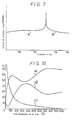
- the metal film 4 is a Te film having a thickness of 100 nm (1000 Angstroms). Its optical absorptance Q , reflectivity p and transmissivity T become different depending on its thickness.
- curves 41, 42 and 43 respectively indicate the relationships of a, p and T to the thickness of the Te film at the wavelength of 830 nm.
- the metal film 4 is not limited to Te, but may be made of Bi, Sb or an alloy of them.
- the thermal conductivities and the melting points of Bi and Sb are 0.085 W/cm.deg, 0.18 W/cm.deg and 271°C, 631°C, respectively.
- thermomagnetic recording medium 5 was irradiated with semiconductor laser light, having a wavelength of 830 nm and a beam diameter of 1 micrometre, from the side of the substrate 6, thereby to carry out the recording on the second magnetised layer 3.
- semiconductor laser light having a wavelength of 830 nm and a beam diameter of 1 micrometre
- an AI film 4 having a thickness of 20 nm (200 Angstroms) was formed on the second magnetised layer 3 to form the thermomagnetic recording medium 5.
- Semiconductor laser light having a wavelength of 830 nm and a beam diameter of 1 micrometre was made incident on the recording medium 5 from the side of the substrate 6 to thereby carry out recording on the second magnetised layer3.
- the pulse width of the laser light was 1 microsecond, the minimum power necessary for recording was 2.8 mW.
- the reason why the necessary power in Example 3 (using Al) is larger than that in Example 2 (which employed Cr) is probably that the AI film has a smaller optical absorptance a than the Cr film.
- Figure 11 shows the calculated results of optical characteristics of Cr and AI films of different thickness to semiconductor laser light (wavelength equal to 830 nm).
- Curves 31 a and 32a indicate the optical absorptan- ces of the Cr and AI films, respectively
- curves 31 p and 32p indicate the reflectivities of the Cr and AI films, respectively
- curves 31 T and 32 T indicate the optical transmissivities of the Cr and AI films, respectively.
Landscapes
- Physics & Mathematics (AREA)
- Optics & Photonics (AREA)
- General Physics & Mathematics (AREA)
- Nonlinear Science (AREA)
Claims (17)
Applications Claiming Priority (4)
| Application Number | Priority Date | Filing Date | Title |
|---|---|---|---|
| JP232433/82 | 1982-12-23 | ||
| JP23243382A JPS59116905A (ja) | 1982-12-23 | 1982-12-23 | 熱磁気光記録方式 |
| JP233239/83 | 1983-12-09 | ||
| JP23323983A JPS60125903A (ja) | 1983-12-09 | 1983-12-09 | 熱磁気光記録方式 |
Publications (3)
| Publication Number | Publication Date |
|---|---|
| EP0128960A1 EP0128960A1 (de) | 1984-12-27 |
| EP0128960A4 EP0128960A4 (de) | 1987-01-20 |
| EP0128960B1 true EP0128960B1 (de) | 1990-04-04 |
Family
ID=26530459
Family Applications (1)
| Application Number | Title | Priority Date | Filing Date |
|---|---|---|---|
| EP84900112A Expired EP0128960B1 (de) | 1982-12-23 | 1983-12-20 | Thermomagnetisches optisches aufzeichnungs-/wiedergabeverfahren |
Country Status (4)
| Country | Link |
|---|---|
| US (1) | US4612587A (de) |
| EP (1) | EP0128960B1 (de) |
| DE (1) | DE3381422D1 (de) |
| WO (1) | WO1984002603A1 (de) |
Families Citing this family (39)
| Publication number | Priority date | Publication date | Assignee | Title |
|---|---|---|---|---|
| JPS60236137A (ja) * | 1984-05-08 | 1985-11-22 | Nippon Kogaku Kk <Nikon> | 同時消録型光磁気記録方式並びにそれに使用する記録装置及び記録媒体 |
| JPH06105507B2 (ja) * | 1984-10-26 | 1994-12-21 | 日本電気株式会社 | 光磁気記録再生消去装置 |
| DE3584945D1 (de) * | 1984-10-30 | 1992-01-30 | Brother Ind Ltd | Magnetooptisches speichermedium und geraet zum schreiben auf und lesen von dem medium. |
| US4771415A (en) * | 1985-02-27 | 1988-09-13 | Brother Kogyo Kabushiki Kaisha | Optical data storage and readout apparatus and head, using optical fibers between stationary and movable units |
| US4635076A (en) * | 1985-03-14 | 1987-01-06 | Minnesota Mining And Manufacturing Company | Two-sided optical recording medium |
| US5239524A (en) * | 1985-06-11 | 1993-08-24 | Nikon Corporation | Over write capable magnetooptical recording method, and magnetooptical recording apparatus and medium used therefor |
| JPH0695404B2 (ja) * | 1985-12-27 | 1994-11-24 | ソニー株式会社 | 光磁気記録方法 |
| NL8600647A (nl) * | 1986-03-13 | 1987-10-01 | Philips Nv | Magneto-optisch registratie-element en een magneto-optische registratie-inrichting. |
| JP2579631B2 (ja) * | 1986-03-27 | 1997-02-05 | キヤノン株式会社 | 光磁気記録方法 |
| EP0243976B1 (de) * | 1986-05-02 | 1996-09-04 | Hitachi, Ltd. | Methode zur Aufzeichnung, Wiedergabe und zum Löschen von Informationen und Dünnfilm zur Aufzeichnung von Informationen |
| US4807204A (en) * | 1986-07-07 | 1989-02-21 | Brother Kogyo Kabushiki Kaisha | Magneto-optical recording medium having pairs of mutually corresponding recording segments, and apparatus for recording information on the medium |
| US6028824A (en) * | 1986-07-08 | 2000-02-22 | Canon Kabushiki Kaisha | Magnetooptical recording medium allowing overwriting with two or more magnetic layers |
| ATE172047T1 (de) * | 1986-07-08 | 1998-10-15 | Canon Kk | Magnetoptisches aufzeichnungsmedium mit der möglichkeit des überschreibens mit zwei oder mehr magnetschichten und dieses medium verwendende aufzeichnungsmethode |
| EP0838814B1 (de) * | 1986-07-08 | 2002-02-27 | Canon Kabushiki Kaisha | Magnetooptisches Aufzeichnungsmedium mit der Möglichkeit des Überschreibens mit zwei oder mehr Magnetschichten und dieses Medium verwendende Aufzeichnungsmethode |
| CA1322408C (en) * | 1986-08-20 | 1993-09-21 | Tomiji Tanaka | Thermomagnetic recording method applying power modulated laser on a magnetically coupled double layer structure of perpendicular anisotropy film |
| JP2570270B2 (ja) * | 1986-10-08 | 1997-01-08 | 株式会社ニコン | ツービームによる光磁気記録方法及び装置 |
| US5014252A (en) * | 1986-10-08 | 1991-05-07 | Nikon Corporation | Over write capable magnetooptical recording method using two beams, and magnetooptical recording apparatus therefor |
| JPS63102031U (de) * | 1986-12-22 | 1988-07-02 | ||
| DE3704146A1 (de) * | 1987-02-11 | 1988-09-29 | Basf Ag | Laseroptisches schreib- und leseverfahren |
| US5265073A (en) * | 1987-03-13 | 1993-11-23 | Canon Kabushiki Kaisha | Overwritable magneto-optical recording medium having two-layer magnetic films wherein one of the films contains one or more of Cu, Ag, Ti, Mn, B, Pt, Si, Ge, Cr and Al, and a method of recording on the same |
| JPS647327A (en) * | 1987-03-25 | 1989-01-11 | Casio Computer Co Ltd | Method and apparatus for optical information recording |
| DE3775049D1 (de) * | 1987-05-08 | 1992-01-16 | Ibm | Loeschbare elektrooptische speicherplatte. |
| JPS6452223A (en) * | 1987-05-14 | 1989-02-28 | Nippon Telegraph & Telephone | Magnetic card |
| JPS63291237A (ja) * | 1987-05-21 | 1988-11-29 | Mitsubishi Electric Corp | 光磁気記録再生用情報担体装置 |
| DE3855347T2 (de) * | 1987-08-08 | 1996-10-31 | Mitsui Petrochemical Ind | Photomagnetisches speichermedium |
| US5210724A (en) * | 1988-03-07 | 1993-05-11 | Canon Kabushiki Kaisha | Optomagnetic recording method and apparatus which precludes an interface magnetic wall within block magnetic wall |
| US5163031A (en) * | 1988-12-07 | 1992-11-10 | Canon Kabushiki Kaisha | Method of recording tetra-value signal on magneto-optical recording medium with plural magnetic layers |
| US5087532A (en) * | 1989-08-01 | 1992-02-11 | Minnesota Mining And Manufacturing Company | Direct-overwrite magneto-optic media |
| US5159584A (en) * | 1989-08-15 | 1992-10-27 | Olympus Optical Company Limited | Bias-Magnetic field generating system of photo-magnetic recording device |
| US5303225A (en) * | 1989-10-30 | 1994-04-12 | Matsushita Electrical Industrial Co., Ltd. | Multi-layered optical disk with track and layer identification |
| USRE37185E1 (en) | 1990-04-20 | 2001-05-22 | Matsushita Electric Industrial Co., Ltd. | Optical head |
| CA2043995C (en) * | 1990-06-13 | 1997-06-24 | Kenji Ohta | Magneto-optical recording/reproducing device |
| US5485452A (en) * | 1991-06-28 | 1996-01-16 | Pioneer Electronic Corporation | Optical information recording medium |
| JP2939018B2 (ja) * | 1991-09-02 | 1999-08-25 | 日本放送協会 | 波長多重記録用光磁気メモリ |
| FR2742911B1 (fr) * | 1995-12-21 | 1998-02-06 | Thomson Csf | Support d'enregistrement/lecture optique d'informations et procede d'enregistrement |
| JP4093681B2 (ja) * | 1999-05-26 | 2008-06-04 | シャープ株式会社 | 熱磁気記録媒体、熱磁気記録方法、熱磁気再生方法、熱磁気記録再生装置 |
| KR100552094B1 (ko) * | 2001-06-22 | 2006-02-13 | 티디케이가부시기가이샤 | 자성 가닛 단결정막 형성용 기판, 광학 소자 및 그 제조방법 |
| RU2428751C2 (ru) * | 2009-09-22 | 2011-09-10 | Федеральное государственное образовательное учреждение высшего профессионального образования "Национальный исследовательский технологический университет "МИСиС" | Термомагнитооптический способ записи информации и устройство для его реализации |
| WO2013179329A1 (ja) * | 2012-05-28 | 2013-12-05 | 株式会社日立製作所 | 光記録媒体及び光情報再生方法 |
Family Cites Families (17)
| Publication number | Priority date | Publication date | Assignee | Title |
|---|---|---|---|---|
| US3181170A (en) * | 1963-07-25 | 1965-04-27 | Northrop Corp | Optical display device |
| US4151602A (en) * | 1975-04-02 | 1979-04-24 | U.S. Philips Corporation | Magnetic bubble multilayer arrangement |
| JPS5255603A (en) * | 1975-10-31 | 1977-05-07 | Nec Corp | Magnetic memory element and production of same |
| JPS5814318B2 (ja) * | 1978-06-26 | 1983-03-18 | 富士写真フイルム株式会社 | 熱的記録材料 |
| US4198692A (en) * | 1978-09-22 | 1980-04-15 | Rockwell International Corporation | Self-biased structure for magnetic bubble domain devices |
| US4285056A (en) * | 1979-10-17 | 1981-08-18 | Rca Corporation | Replicable optical recording medium |
| JPS5674843A (en) * | 1979-11-21 | 1981-06-20 | Fuji Photo Film Co Ltd | Photomagnetic recording medium |
| US4299680A (en) * | 1979-12-31 | 1981-11-10 | Texas Instruments Incorporated | Method of fabricating magnetic bubble memory device having planar overlay pattern of magnetically soft material |
| JPS56117345A (en) * | 1980-02-22 | 1981-09-14 | Nippon Hoso Kyokai <Nhk> | Optical recording medium |
| JPS56153546A (en) * | 1980-04-28 | 1981-11-27 | Ricoh Co Ltd | Magnetic recording medium |
| JPS592094B2 (ja) * | 1980-08-25 | 1984-01-17 | ケイディディ株式会社 | 層状光磁気記録媒体 |
| JPS5766549A (en) * | 1980-10-09 | 1982-04-22 | Sharp Corp | Magnetooptical storage element |
| CA1185013A (en) * | 1981-01-14 | 1985-04-02 | Kenji Ohta | Magneto-optic memory medium |
| DE3278703D1 (en) * | 1981-03-26 | 1988-07-28 | Sony Corp | Thermomagnetic recording methods |
| JPS5850639A (ja) * | 1981-09-18 | 1983-03-25 | Ricoh Co Ltd | 垂直磁化記録媒体 |
| JPS58153244A (ja) * | 1982-03-05 | 1983-09-12 | Matsushita Electric Ind Co Ltd | 光磁気記録媒体 |
| GB2110459B (en) * | 1982-11-08 | 1985-08-14 | Kokusai Denshin Denwa Co Ltd | Magneto-optical recording system |
-
1983
- 1983-12-20 WO PCT/JP1983/000445 patent/WO1984002603A1/ja not_active Ceased
- 1983-12-20 DE DE8484900112T patent/DE3381422D1/de not_active Expired - Lifetime
- 1983-12-20 US US06/643,976 patent/US4612587A/en not_active Expired - Fee Related
- 1983-12-20 EP EP84900112A patent/EP0128960B1/de not_active Expired
Also Published As
| Publication number | Publication date |
|---|---|
| EP0128960A1 (de) | 1984-12-27 |
| US4612587A (en) | 1986-09-16 |
| DE3381422D1 (de) | 1990-05-10 |
| EP0128960A4 (de) | 1987-01-20 |
| WO1984002603A1 (fr) | 1984-07-05 |
Similar Documents
| Publication | Publication Date | Title |
|---|---|---|
| EP0128960B1 (de) | Thermomagnetisches optisches aufzeichnungs-/wiedergabeverfahren | |
| US4649519A (en) | Self biasing thermal magneto-optic medium | |
| EP0217096B1 (de) | Löschbares, selbstpolarisiertes, thermisches magnetooptisches Medium | |
| US4799114A (en) | Thermomagnetic recording carrier and a method for thermomagnetic recording | |
| EP0509836B1 (de) | Magneto-optisches Aufzeichnungsmedium | |
| US5208799A (en) | Magneto-optic recording method and magneto-optic recording/reproducing apparatus | |
| JPS5945646A (ja) | 光学的情報再生装置 | |
| CA1177577A (en) | Magnetooptical recording medium and recording-and- reproducing device using the same | |
| JP2579631B2 (ja) | 光磁気記録方法 | |
| Fan et al. | Low‐Temperature Beam‐Addressable Memory | |
| EP0740297B1 (de) | Magnetooptisches Verfahren und Gerät zur Aufzeichnung/Wiedergabe von Daten | |
| EP0129605A1 (de) | Thermomagnetisches optisches aufzeichnungsverfahren | |
| JPH0782672B2 (ja) | 磁性薄膜記録媒体 | |
| JPH0614416B2 (ja) | 光磁気記録再生方法 | |
| JPH02267754A (ja) | 磁気光学記録媒体 | |
| JPS61131288A (ja) | 固体メモリ− | |
| JPS60125903A (ja) | 熱磁気光記録方式 | |
| JP2790685B2 (ja) | 光磁気記録方法 | |
| JP3626211B2 (ja) | 光記録媒体の信号再生方法 | |
| JPH0231356A (ja) | 情報記録再生装置 | |
| EP0104919B1 (de) | Thermomagnetische Aufnahmeverfahren | |
| JPS6064376A (ja) | 磁気ホログラム記録方法 | |
| JPS59116905A (ja) | 熱磁気光記録方式 | |
| JP2538916B2 (ja) | 光磁気記録用媒体 | |
| JP2604702B2 (ja) | 光磁気記録再生消去方式及びその装置 |
Legal Events
| Date | Code | Title | Description |
|---|---|---|---|
| PUAI | Public reference made under article 153(3) epc to a published international application that has entered the european phase |
Free format text: ORIGINAL CODE: 0009012 |
|
| 17P | Request for examination filed |
Effective date: 19840908 |
|
| AK | Designated contracting states |
Designated state(s): DE FR GB NL |
|
| A4 | Supplementary search report drawn up and despatched |
Effective date: 19870120 |
|
| 17Q | First examination report despatched |
Effective date: 19881007 |
|
| GRAA | (expected) grant |
Free format text: ORIGINAL CODE: 0009210 |
|
| AK | Designated contracting states |
Kind code of ref document: B1 Designated state(s): DE FR GB NL |
|
| REF | Corresponds to: |
Ref document number: 3381422 Country of ref document: DE Date of ref document: 19900510 |
|
| ET | Fr: translation filed | ||
| PLBE | No opposition filed within time limit |
Free format text: ORIGINAL CODE: 0009261 |
|
| STAA | Information on the status of an ep patent application or granted ep patent |
Free format text: STATUS: NO OPPOSITION FILED WITHIN TIME LIMIT |
|
| 26N | No opposition filed | ||
| PGFP | Annual fee paid to national office [announced via postgrant information from national office to epo] |
Ref country code: FR Payment date: 19941209 Year of fee payment: 12 |
|
| PGFP | Annual fee paid to national office [announced via postgrant information from national office to epo] |
Ref country code: GB Payment date: 19941212 Year of fee payment: 12 |
|
| PGFP | Annual fee paid to national office [announced via postgrant information from national office to epo] |
Ref country code: DE Payment date: 19941222 Year of fee payment: 12 |
|
| PGFP | Annual fee paid to national office [announced via postgrant information from national office to epo] |
Ref country code: NL Payment date: 19941231 Year of fee payment: 12 |
|
| PG25 | Lapsed in a contracting state [announced via postgrant information from national office to epo] |
Ref country code: GB Effective date: 19951220 |
|
| PG25 | Lapsed in a contracting state [announced via postgrant information from national office to epo] |
Ref country code: NL Effective date: 19960701 |
|
| GBPC | Gb: european patent ceased through non-payment of renewal fee |
Effective date: 19951220 |
|
| PG25 | Lapsed in a contracting state [announced via postgrant information from national office to epo] |
Ref country code: FR Effective date: 19960830 |
|
| NLV4 | Nl: lapsed or anulled due to non-payment of the annual fee |
Effective date: 19960701 |
|
| PG25 | Lapsed in a contracting state [announced via postgrant information from national office to epo] |
Ref country code: DE Effective date: 19960903 |
|
| REG | Reference to a national code |
Ref country code: FR Ref legal event code: ST |