EP0129068A1 - Relais électromagnétique miniaturisé et méthode de fabrication - Google Patents
Relais électromagnétique miniaturisé et méthode de fabrication Download PDFInfo
- Publication number
- EP0129068A1 EP0129068A1 EP84105622A EP84105622A EP0129068A1 EP 0129068 A1 EP0129068 A1 EP 0129068A1 EP 84105622 A EP84105622 A EP 84105622A EP 84105622 A EP84105622 A EP 84105622A EP 0129068 A1 EP0129068 A1 EP 0129068A1
- Authority
- EP
- European Patent Office
- Prior art keywords
- armature
- coil
- core
- fixed contact
- spring
- Prior art date
- Legal status (The legal status is an assumption and is not a legal conclusion. Google has not performed a legal analysis and makes no representation as to the accuracy of the status listed.)
- Granted
Links
- 238000004519 manufacturing process Methods 0.000 title claims description 6
- 238000000034 method Methods 0.000 title claims 3
- 238000004804 winding Methods 0.000 claims description 11
- 230000001681 protective effect Effects 0.000 claims description 6
- 239000011810 insulating material Substances 0.000 claims description 3
- 230000005284 excitation Effects 0.000 claims description 2
- 238000000926 separation method Methods 0.000 claims 1
- POIUWJQBRNEFGX-XAMSXPGMSA-N cathelicidin Chemical compound C([C@@H](C(=O)N[C@@H](CCCNC(N)=N)C(=O)N[C@@H](CCCCN)C(=O)N[C@@H](CO)C(=O)N[C@@H](CCCCN)C(=O)N[C@@H](CCC(O)=O)C(=O)N[C@@H](CCCCN)C(=O)N[C@@H]([C@@H](C)CC)C(=O)NCC(=O)N[C@@H](CCCCN)C(=O)N[C@@H](CCC(O)=O)C(=O)N[C@@H](CC=1C=CC=CC=1)C(=O)N[C@@H](CCCCN)C(=O)N[C@@H](CCCNC(N)=N)C(=O)N[C@@H]([C@@H](C)CC)C(=O)N[C@@H](C(C)C)C(=O)N[C@@H](CCC(N)=O)C(=O)N[C@@H](CCCNC(N)=N)C(=O)N[C@@H]([C@@H](C)CC)C(=O)N[C@@H](CCCCN)C(=O)N[C@@H](CC(O)=O)C(=O)N[C@@H](CC=1C=CC=CC=1)C(=O)N[C@@H](CC(C)C)C(=O)N[C@@H](CCCNC(N)=N)C(=O)N[C@@H](CC(N)=O)C(=O)N[C@@H](CC(C)C)C(=O)N[C@@H](C(C)C)C(=O)N1[C@@H](CCC1)C(=O)N[C@@H](CCCNC(N)=N)C(=O)N[C@@H]([C@@H](C)O)C(=O)N[C@@H](CCC(O)=O)C(=O)N[C@@H](CO)C(O)=O)NC(=O)[C@H](CC=1C=CC=CC=1)NC(=O)[C@H](CC(O)=O)NC(=O)CNC(=O)[C@H](CC(C)C)NC(=O)[C@@H](N)CC(C)C)C1=CC=CC=C1 POIUWJQBRNEFGX-XAMSXPGMSA-N 0.000 description 3
- 230000013011 mating Effects 0.000 description 3
- 239000002184 metal Substances 0.000 description 3
- 238000010276 construction Methods 0.000 description 2
- 238000004382 potting Methods 0.000 description 2
- 238000003466 welding Methods 0.000 description 2
- KGNDCEVUMONOKF-UGPLYTSKSA-N benzyl n-[(2r)-1-[(2s,4r)-2-[[(2s)-6-amino-1-(1,3-benzoxazol-2-yl)-1,1-dihydroxyhexan-2-yl]carbamoyl]-4-[(4-methylphenyl)methoxy]pyrrolidin-1-yl]-1-oxo-4-phenylbutan-2-yl]carbamate Chemical compound C1=CC(C)=CC=C1CO[C@H]1CN(C(=O)[C@@H](CCC=2C=CC=CC=2)NC(=O)OCC=2C=CC=CC=2)[C@H](C(=O)N[C@@H](CCCCN)C(O)(O)C=2OC3=CC=CC=C3N=2)C1 KGNDCEVUMONOKF-UGPLYTSKSA-N 0.000 description 1
- 229940125833 compound 23 Drugs 0.000 description 1
- 150000001875 compounds Chemical class 0.000 description 1
- 238000009826 distribution Methods 0.000 description 1
Images

Classifications
-
- H—ELECTRICITY
- H01—ELECTRIC ELEMENTS
- H01H—ELECTRIC SWITCHES; RELAYS; SELECTORS; EMERGENCY PROTECTIVE DEVICES
- H01H50/00—Details of electromagnetic relays
- H01H50/54—Contact arrangements
- H01H50/60—Contact arrangements moving contact being rigidly combined with movable part of magnetic circuit
-
- H—ELECTRICITY
- H01—ELECTRIC ELEMENTS
- H01H—ELECTRIC SWITCHES; RELAYS; SELECTORS; EMERGENCY PROTECTIVE DEVICES
- H01H50/00—Details of electromagnetic relays
- H01H50/02—Bases; Casings; Covers
- H01H50/04—Mounting complete relay or separate parts of relay on a base or inside a case
- H01H50/041—Details concerning assembly of relays
- H01H50/043—Details particular to miniaturised relays
-
- Y—GENERAL TAGGING OF NEW TECHNOLOGICAL DEVELOPMENTS; GENERAL TAGGING OF CROSS-SECTIONAL TECHNOLOGIES SPANNING OVER SEVERAL SECTIONS OF THE IPC; TECHNICAL SUBJECTS COVERED BY FORMER USPC CROSS-REFERENCE ART COLLECTIONS [XRACs] AND DIGESTS
- Y10—TECHNICAL SUBJECTS COVERED BY FORMER USPC
- Y10T—TECHNICAL SUBJECTS COVERED BY FORMER US CLASSIFICATION
- Y10T29/00—Metal working
- Y10T29/49—Method of mechanical manufacture
- Y10T29/49002—Electrical device making
- Y10T29/49105—Switch making
Definitions
- the invention relates to a small electromagnetic relay with a flat core arranged within an excitation coil, the ends of which emerge from the coil each form pole faces for an armature which is arranged next to the coil and is in contact with both pole faces when the coil is excited, and with one from the armature actuatable contact arrangement.
- the invention also relates to a method for producing such a relay.
- Electromagnetic relays with the above-mentioned basic structure have long been known. These conventional so-called flat relays have a single-sided armature that actuates contact spring sets attached to the side of the relay via an actuating slide. However, this conventional design with separately applied contact spring sets is not for miniaturization. suitable.
- the object of the invention is to provide a particularly simple small relay with the basic structure mentioned at the beginning, which can be produced with a few simple parts.
- the size and connection configuration of the relay should be able to be adapted to integrated circuit modules and, despite the minimal size, be able to switch relatively large currents.
- this object is achieved in that Area of both armature ends, at least one fixed contact element provided with a connecting pin is anchored in a base body carrying the coil and that a contact spring extending in the longitudinal direction of the armature and approximately centrally fastened to it electrically connects two fixed contact elements to one another at least in one end position.
- the relay according to the invention allows a very flat bzu. Narrow construction, since in one direction only the thickness of the core punched from a sheet metal is summed up with the thickness of the coil winding including the coil former and with the thickness of the armature likewise made of a flat sheet metal with a flat contact spring attached.
- the fixed contact elements are located in front of the two armature ends and therefore do not increase the depth of the relay structure in any case, if only two fixed contact elements are provided for a normally open or normally closed contact.
- the armature can be mounted on one of the pole faces and only form a working air gap with the second pole face of the core.
- the contact spring fastened on the armature is firmly connected to the one fixed contact element and only with its other free end in switching connection with one or two fixed mating contact elements.
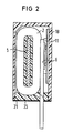
- a particularly advantageous embodiment of the invention consists in that the armature forms working air gaps with both pole faces of the core, i.e. carries out a translational switching movement in a direction perpendicular to the coil axis, the contact spring attached to it also making a switching movement with each of its two ends as a bridge contact spring executes against a mating contact element. Due to the double contact opening with the bridge contact spring and the arrangement of the associated fixed contact elements on opposite ends of the relay with correspondingly large insulating distances, it is possible to switch relatively strong currents even with a very small construction and very little armature stroke.
- the rest position of the armature is expediently generated by a return spring designed as a leaf spring which, like the contact spring, lies flat on the armature and rests with its free ends on contact surfaces of the base body.
- a return spring is provided on both sides of the contact spring, the return spring or the return springs being connected in one piece with the contact spring in its central section and only with their free ones in a particularly simple embodiment Ends are cut free.
- the armature is expediently supported on a housing cap against which it is biased by the return spring.
- the base body expediently serves simultaneously as a coil former and as a carrier for the fixed contact elements and, if appropriate, for coil connections ment.
- the core and the fixed contact elements can be embedded in the base body, so that only the pole faces of the core and the contacting surfaces of the fixed contact elements are exposed.
- the base body is formed by embedding the flat core and the fixed contact elements and provided with the coil winding, that the armature provided with the contact spring and a return spring is then attached laterally to the base body and by fitting one Protective cap secured.
- the core and the mating contact elements are first punched out of a common circuit board and cut apart with the exception of one holding web hanging from a guide strip, then embedded together in insulating material and then separated from the guide strip.
- the coil connecting pins can also be punched out of the common circuit board, embedded with them and bent into a desired grid position after the coil has been wound.
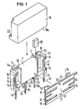
- the base body 1 to 3 consists of a base body 1, which serves both as a coil former and as a contact carrier.
- This base body 1 carries in its central part a winding 2 which is delimited at both ends by the flanges 3 and 4.
- a flat core 5 is embedded within the coil winding, the ends of which come out of the coil and end in chambers 3a bzu.
- 4a of the flanges 3 and 4 each have a pole face 5a bzu. 5b forms.
- the coil flanges 3 and 4 formed by the base body 1 also each have fixed contact elements 6 b on the end faces in front of the pole faces 5 a and 5 b. 7, which are embedded in the base body and form connecting pins 6a and 7a which project downward.
- the contact elements 6 and 7 are each provided with contact surfaces 8.
- the base body carries on the underside two coil connection elements 9 and 10, which have connection spikes 9a and 10a protruding downwards in a row with the connection spikes 6a and 7a of the contact elements and also form winding support points 9b and 10b for the winding ends 2a and 2b.
- An armature 11, like the core 5, consists of a flat sheet metal, the armature ends 11a and 11b each being cranked so that they can lie flat on the respective pole faces 5a and 5b of the core.
- the armature 11 carries on its outer surface facing away from the coil a combined contact and return spring 12 which is fastened with its central part to the armature via welding spots 13 or in some other way.
- the outer spring ends 15 serve as return springs, which are each supported on contact surfaces 16 of the base body when the armature in the direction of Arrow 17 in that Relay is used.
- the armature is secured against falling out by fitting a protective cap 18, it being pressed against the protective cap by the restoring force of the return springs 15.
- the return springs 15 it would also be conceivable for the armature to rest with one end 11a or 11b in the rest position on the corresponding pole face 5a or 5b and to perform a pivoting movement about the relevant armature end when switching.
- all return springs 15 will be biased equally, so that the armature performs a translational switching movement in the direction of arrow 17 perpendicular to the coil axis when switching.
- the base body 1 also has a space 19 for receiving a getter 20.
- the relay can be tightly closed by attaching a film 21 from the underside to the connecting spikes 6a, 7a, 9a and 10a and welding bzu to the edge 18a of the protective cap. is glued.
- a potting compound 23 can then be filled in to a certain level via a siphon-like opening 22 in the cap 18, as a result of which the opening 22 is also sealed when the potting compound hardens.
- the pins 6a, 7a, 9a and 10a of the relay protrude downwards in a row from the relay housing.
- the relay can thus be used as a very narrow component on a circuit board. If necessary, it is also possible to bend the connecting pins 6a, 7a, 9a and 10a in a row about a common axis by 90 °, so that the relay lies very flat on a circuit board.
- Fig. 3 the relay according to Fig. 1 is shown in different manufacturing stages.
- the core 5 with the contact elements 6 and 7 and with the coil connecting pins 9 and 10 is punched out of a common circuit board 24, all parts being connected via the connecting pins 6a, 7a, the Uickel support points 9b, 10b and remain connected to the circuit board strip 24 via retaining webs 25. All these parts are then encapsulated with insulating material to form the base body 1.
- the connecting pins are then cut free from the strip 24 and the retaining webs 25 are separated.
- the coil winding 2 is applied to the base body, the winding ends 2a and 2b being wound onto the respective winding support points 9b and 10b.
- the coil connecting pins 9 and 10 can be bent over the underside of the winding, so that the connecting spikes 9a and 10a protrude parallel to the connecting spikes 6a and 7a of the contact elements to the underside of the relay.
- the armature 11 with the spring 12 can then be inserted and the relay can be closed with the protective cap 18.
Landscapes
- Physics & Mathematics (AREA)
- Electromagnetism (AREA)
- Electromagnets (AREA)
Applications Claiming Priority (2)
| Application Number | Priority Date | Filing Date | Title |
|---|---|---|---|
| DE3318493 | 1983-05-20 | ||
| DE19833318493 DE3318493A1 (de) | 1983-05-20 | 1983-05-20 | Elektromagnetisches kleinrelais und verfahren zu dessen herstellung |
Publications (2)
| Publication Number | Publication Date |
|---|---|
| EP0129068A1 true EP0129068A1 (fr) | 1984-12-27 |
| EP0129068B1 EP0129068B1 (fr) | 1987-04-15 |
Family
ID=6199556
Family Applications (1)
| Application Number | Title | Priority Date | Filing Date |
|---|---|---|---|
| EP84105622A Expired EP0129068B1 (fr) | 1983-05-20 | 1984-05-17 | Relais électromagnétique miniaturisé et méthode de fabrication |
Country Status (4)
| Country | Link |
|---|---|
| US (1) | US4517537A (fr) |
| EP (1) | EP0129068B1 (fr) |
| JP (1) | JPS59224024A (fr) |
| DE (2) | DE3318493A1 (fr) |
Families Citing this family (18)
| Publication number | Priority date | Publication date | Assignee | Title |
|---|---|---|---|---|
| DE8506345U1 (de) * | 1985-03-05 | 1986-07-03 | Siemens AG, 1000 Berlin und 8000 München | Kontaktanordnung in einem Relais für hohe Schaltleistung |
| US4684909A (en) * | 1985-03-26 | 1987-08-04 | Siemens Aktiengesellschaft | Electromagnetic relay |
| US4713727A (en) * | 1985-10-30 | 1987-12-15 | Siemens Aktiengesellschaft | Electromechanical component with sealed housing |
| US5079098A (en) * | 1988-03-16 | 1992-01-07 | Loctite Corporation | Primer for bonding low surface energy plastics with cyanoacrylate adhesives and bonding method employing same |
| DE3813119A1 (de) * | 1988-04-15 | 1989-10-26 | Siemens Ag | Spulenkoerper und verfahren zur herstellung eines spulenkoerpers |
| US5070315A (en) * | 1989-05-26 | 1991-12-03 | Omron Corporation | Electromagnetic relay |
| US5038123A (en) * | 1989-12-14 | 1991-08-06 | General Motors Corporation | Flat electromagnetic relay |
| AU1672992A (en) * | 1991-04-22 | 1992-11-17 | Omron Corporation | Sealed electromagnetic relay |
| US5148136A (en) * | 1991-08-19 | 1992-09-15 | General Motors Corporation | Flat electromagnetic relay |
| US5325079A (en) * | 1993-01-21 | 1994-06-28 | Kaloust P. Sogoian | Electromagnetic relay with integral contacts |
| DE19544624C1 (de) * | 1995-11-30 | 1997-01-02 | Hella Kg Hueck & Co | Elektromagnetisches Klappankerrelais |
| US6247546B1 (en) | 1999-05-06 | 2001-06-19 | Sandia Corporation | Hopping robot |
| US6328002B1 (en) | 1999-05-06 | 2001-12-11 | Sandia Corporation | Misfire tolerant combustion-powered actuation |
| US6286386B1 (en) | 1999-05-06 | 2001-09-11 | Sandia Corporation | Passive orientation apparatus |
| US6308791B1 (en) | 1999-05-06 | 2001-10-30 | Sandia Corporation | Steerable vertical to horizontal energy transducer for mobile robots |
| JP2003242873A (ja) * | 2002-02-19 | 2003-08-29 | Fujitsu Component Ltd | マイクロリレー |
| US20070290646A1 (en) * | 2006-06-17 | 2007-12-20 | Tyco Electronics Corporation | Soft start time delay relay |
| US20070290776A1 (en) * | 2006-06-17 | 2007-12-20 | Tim Hasenour | Time delay relay |
Citations (4)
| Publication number | Priority date | Publication date | Assignee | Title |
|---|---|---|---|---|
| DE1816364A1 (de) * | 1968-12-21 | 1970-07-09 | Westfaelische Metall Industrie | Elektromagnetisches Relais,insbesondere fuer Kraftfahrzeuge |
| US3717829A (en) * | 1971-08-27 | 1973-02-20 | Allied Control Co | Electromagnetic relay |
| CA977014A (en) * | 1973-06-08 | 1975-10-28 | United-Carr Divisions Of Trw Canada Limited | Simple automotive relay |
| DE2537462A1 (de) * | 1974-08-22 | 1976-03-11 | Matsushita Electric Works Ltd | Elektromagnetisches schuetz |
Family Cites Families (4)
| Publication number | Priority date | Publication date | Assignee | Title |
|---|---|---|---|---|
| BE472266A (fr) * | 1943-07-07 | |||
| DE1639232B1 (de) * | 1966-03-20 | 1972-10-05 | Electronic Controls Inc | Elektromagnetisches Relais |
| US3708768A (en) * | 1971-06-18 | 1973-01-02 | Datron Syst Inc | Miniature relay |
| IT1046855B (it) * | 1975-01-31 | 1980-07-31 | Fiamm Spa | Role elettromagnetic di piccolo imgombro in particolare per autoveicoli |
-
1983
- 1983-05-20 DE DE19833318493 patent/DE3318493A1/de not_active Withdrawn
-
1984
- 1984-05-11 US US06/609,305 patent/US4517537A/en not_active Expired - Fee Related
- 1984-05-15 JP JP59095778A patent/JPS59224024A/ja active Pending
- 1984-05-17 DE DE8484105622T patent/DE3463198D1/de not_active Expired
- 1984-05-17 EP EP84105622A patent/EP0129068B1/fr not_active Expired
Patent Citations (4)
| Publication number | Priority date | Publication date | Assignee | Title |
|---|---|---|---|---|
| DE1816364A1 (de) * | 1968-12-21 | 1970-07-09 | Westfaelische Metall Industrie | Elektromagnetisches Relais,insbesondere fuer Kraftfahrzeuge |
| US3717829A (en) * | 1971-08-27 | 1973-02-20 | Allied Control Co | Electromagnetic relay |
| CA977014A (en) * | 1973-06-08 | 1975-10-28 | United-Carr Divisions Of Trw Canada Limited | Simple automotive relay |
| DE2537462A1 (de) * | 1974-08-22 | 1976-03-11 | Matsushita Electric Works Ltd | Elektromagnetisches schuetz |
Also Published As
| Publication number | Publication date |
|---|---|
| DE3463198D1 (en) | 1987-05-21 |
| JPS59224024A (ja) | 1984-12-15 |
| US4517537A (en) | 1985-05-14 |
| DE3318493A1 (de) | 1984-11-22 |
| EP0129068B1 (fr) | 1987-04-15 |
Similar Documents
| Publication | Publication Date | Title |
|---|---|---|
| EP0129068A1 (fr) | Relais électromagnétique miniaturisé et méthode de fabrication | |
| DE4135305C2 (fr) | ||
| EP0281950B1 (fr) | Relais électromagnétique | |
| DE60017102T2 (de) | Elektromagnetisches relais | |
| DE9211726U1 (de) | Elektromagnetisches Relais | |
| DE3406832C2 (de) | Klappankerrelais | |
| DE2659895A1 (de) | Elektrischer schalter | |
| DE2950199C2 (de) | Hermetisch abgedichtetes elektromagnetisches Relais | |
| DE3835105A1 (de) | Elektromagnetisches relais | |
| CH630200A5 (de) | Elektromagnetische antriebsvorrichtung fuer ein miniaturrelais mit einem elektromagneten und miniaturrelais mit einer solchen antriebsvorrichtung. | |
| DE19727863C1 (de) | Elektromagnetisches Relais | |
| DE2256044B2 (de) | Umschaltkontakt | |
| DE2716491A1 (de) | Schalter | |
| EP0805520A2 (fr) | Connecteur de bords d'une carte à circuits imprimés | |
| DE60031223T2 (de) | Hochfrequenzrelais | |
| DE2545180C3 (de) | Miniaturrelais | |
| DE2118633A1 (de) | Elektromagnetisches Relais | |
| DE8235283U1 (de) | Elektromagnetisches Relais | |
| EP0252344A1 (fr) | Relais électromagnétique | |
| DE2811378A1 (de) | Elektromagnetisches relais | |
| DE2146407C3 (de) | Flachrelais in Miniaturbauweise | |
| DE3508795C2 (fr) | ||
| DE3147563A1 (de) | Kontaktfedersatz | |
| EP0291019B1 (fr) | Relais électromagnétique | |
| DE69800013T2 (de) | Elektromagnetisches Relais |
Legal Events
| Date | Code | Title | Description |
|---|---|---|---|
| PUAI | Public reference made under article 153(3) epc to a published international application that has entered the european phase |
Free format text: ORIGINAL CODE: 0009012 |
|
| AK | Designated contracting states |
Designated state(s): CH DE FR GB LI |
|
| 17P | Request for examination filed |
Effective date: 19841128 |
|
| GRAA | (expected) grant |
Free format text: ORIGINAL CODE: 0009210 |
|
| AK | Designated contracting states |
Kind code of ref document: B1 Designated state(s): CH DE FR GB LI |
|
| REF | Corresponds to: |
Ref document number: 3463198 Country of ref document: DE Date of ref document: 19870521 |
|
| ET | Fr: translation filed | ||
| PLBE | No opposition filed within time limit |
Free format text: ORIGINAL CODE: 0009261 |
|
| STAA | Information on the status of an ep patent application or granted ep patent |
Free format text: STATUS: NO OPPOSITION FILED WITHIN TIME LIMIT |
|
| 26N | No opposition filed | ||
| PG25 | Lapsed in a contracting state [announced via postgrant information from national office to epo] |
Ref country code: GB Effective date: 19880517 |
|
| GBPC | Gb: european patent ceased through non-payment of renewal fee | ||
| PGFP | Annual fee paid to national office [announced via postgrant information from national office to epo] |
Ref country code: FR Payment date: 19960523 Year of fee payment: 13 |
|
| PGFP | Annual fee paid to national office [announced via postgrant information from national office to epo] |
Ref country code: CH Payment date: 19960821 Year of fee payment: 13 |
|
| PG25 | Lapsed in a contracting state [announced via postgrant information from national office to epo] |
Ref country code: LI Free format text: LAPSE BECAUSE OF NON-PAYMENT OF DUE FEES Effective date: 19970531 Ref country code: CH Free format text: LAPSE BECAUSE OF NON-PAYMENT OF DUE FEES Effective date: 19970531 |
|
| PGFP | Annual fee paid to national office [announced via postgrant information from national office to epo] |
Ref country code: DE Payment date: 19970721 Year of fee payment: 14 |
|
| REG | Reference to a national code |
Ref country code: CH Ref legal event code: PL |
|
| PG25 | Lapsed in a contracting state [announced via postgrant information from national office to epo] |
Ref country code: FR Free format text: LAPSE BECAUSE OF NON-PAYMENT OF DUE FEES Effective date: 19980130 |
|
| REG | Reference to a national code |
Ref country code: FR Ref legal event code: ST |
|
| PG25 | Lapsed in a contracting state [announced via postgrant information from national office to epo] |
Ref country code: DE Free format text: LAPSE BECAUSE OF NON-PAYMENT OF DUE FEES Effective date: 19990302 |