EP0129083A1 - Connecteur pour câbles plats et connection comportant ce connecteur - Google Patents
Connecteur pour câbles plats et connection comportant ce connecteur Download PDFInfo
- Publication number
- EP0129083A1 EP0129083A1 EP84105766A EP84105766A EP0129083A1 EP 0129083 A1 EP0129083 A1 EP 0129083A1 EP 84105766 A EP84105766 A EP 84105766A EP 84105766 A EP84105766 A EP 84105766A EP 0129083 A1 EP0129083 A1 EP 0129083A1
- Authority
- EP
- European Patent Office
- Prior art keywords
- arm
- hollow cylindrical
- cylindrical relief
- connector
- flat cable
- Prior art date
- Legal status (The legal status is an assumption and is not a legal conclusion. Google has not performed a legal analysis and makes no representation as to the accuracy of the status listed.)
- Granted
Links
- 239000004020 conductor Substances 0.000 claims description 28
- 238000009413 insulation Methods 0.000 claims description 8
- 239000011810 insulating material Substances 0.000 claims description 7
- 238000004049 embossing Methods 0.000 claims description 6
- 230000015572 biosynthetic process Effects 0.000 claims description 4
- 230000000694 effects Effects 0.000 claims description 4
- 239000007769 metal material Substances 0.000 claims description 4
- 230000008878 coupling Effects 0.000 claims description 3
- 238000010168 coupling process Methods 0.000 claims description 3
- 238000005859 coupling reaction Methods 0.000 claims description 3
- 230000000063 preceeding effect Effects 0.000 claims 2
- 239000000463 material Substances 0.000 description 5
- 230000002045 lasting effect Effects 0.000 description 2
- 230000000750 progressive effect Effects 0.000 description 2
- 238000004873 anchoring Methods 0.000 description 1
- 238000005452 bending Methods 0.000 description 1
- 230000005540 biological transmission Effects 0.000 description 1
- 230000000295 complement effect Effects 0.000 description 1
- 238000001816 cooling Methods 0.000 description 1
- 238000010438 heat treatment Methods 0.000 description 1
- 230000037431 insertion Effects 0.000 description 1
- 238000003780 insertion Methods 0.000 description 1
- 239000002184 metal Substances 0.000 description 1
- 239000004753 textile Substances 0.000 description 1
- 210000002105 tongue Anatomy 0.000 description 1
Images
Classifications
-
- H—ELECTRICITY
- H01—ELECTRIC ELEMENTS
- H01R—ELECTRICALLY-CONDUCTIVE CONNECTIONS; STRUCTURAL ASSOCIATIONS OF A PLURALITY OF MUTUALLY-INSULATED ELECTRICAL CONNECTING ELEMENTS; COUPLING DEVICES; CURRENT COLLECTORS
- H01R12/00—Structural associations of a plurality of mutually-insulated electrical connecting elements, specially adapted for printed circuits, e.g. printed circuit boards [PCB], flat or ribbon cables, or like generally planar structures, e.g. terminal strips, terminal blocks; Coupling devices specially adapted for printed circuits, flat or ribbon cables, or like generally planar structures; Terminals specially adapted for contact with, or insertion into, printed circuits, flat or ribbon cables, or like generally planar structures
- H01R12/50—Fixed connections
- H01R12/59—Fixed connections for flexible printed circuits, flat or ribbon cables or like structures
- H01R12/65—Fixed connections for flexible printed circuits, flat or ribbon cables or like structures characterised by the terminal
- H01R12/67—Fixed connections for flexible printed circuits, flat or ribbon cables or like structures characterised by the terminal insulation penetrating terminals
- H01R12/68—Fixed connections for flexible printed circuits, flat or ribbon cables or like structures characterised by the terminal insulation penetrating terminals comprising deformable portions
-
- H—ELECTRICITY
- H01—ELECTRIC ELEMENTS
- H01R—ELECTRICALLY-CONDUCTIVE CONNECTIONS; STRUCTURAL ASSOCIATIONS OF A PLURALITY OF MUTUALLY-INSULATED ELECTRICAL CONNECTING ELEMENTS; COUPLING DEVICES; CURRENT COLLECTORS
- H01R4/00—Electrically-conductive connections between two or more conductive members in direct contact, i.e. touching one another; Means for effecting or maintaining such contact; Electrically-conductive connections having two or more spaced connecting locations for conductors and using contact members penetrating insulation
- H01R4/24—Connections using contact members penetrating or cutting insulation or cable strands
Definitions
- the known connectors of the second group although assuring a very good mechanical connection between connector and flat cable lasting in time and a small encumbrance of the connection, they are not able to originate a good electrical connection since the contact between connector and conductor of the flat cable takes place only in correspondence of the cable thickness and consequently the surface where the contact takes place is obviously very small.
- connectors which associate to the connecting means provided in said second group the means belonging to the first group of connectors.
- the object of the present invention is a connector for flat cables comprising a metallic material plate which can be folded along an intermediate line so as to determine a first and a second arm, means provided in the arms apt to couple to each other and to a flat cable interposed to effect contemporaneously a mechanical connection and an electrical connection with the cable conductor, characterized by the fact that said means comprise:
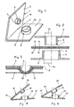
- Figure 1 represents a connector according to the invention.
- a connector according to the present invention is constituted by a metallic plate 1 which can be folded along an intermediate line 2 so as to originate in the plate 1 a pair of arms, more precisely a fir t arm 3 and a second arm 4.
- the difference between the inner radius R of the second hollow cylindrical relief and the outer radius R of the first hollow cylindrical relief 5 is not lower than 1/3 of the thickness of the conductor of the flat cable to be interposed between the first arm 3 and the second arm 4 of the connector 1.
- the cylindrical reliefs projecting from the facing surfaces of the connector arms have in straight section a circular shape, but this shape must be understood as in a non-limiting sense since said cylinders can have other shapes as for instance an elliptic shape and the like, or even a polygonal shape.
- Figure 2 represents in enlarged scale and in section the particular of the hollow cylindrical reliefs of a connector according to the invention between which a flat cable is interposed before the connection between the connector and this latter.
- An electrical connection with a flat cable is carried out by means of a connector according to the present invention previously described and said electrical connection forms the object of the present invention too.
- Figure 2 represents the situation in which the hollow cylindrical reliefs 5 and 6 belonging respectively to the arms 3 and 4 of the connector are before the contact of said hollow cylindrical elements with the flat cable.
- the cylindrical reliefs 5 and 6, which are supported by the arms 3 and 4, going into contact with the flat cable 9 provide firstly to cut the layers of insulating material 11 and 12 present on the faces of the flat cable.
- the hollow cylindrical reliefs 5 and 6 deform the flat cable (with the formation in said flat cable of a flat bottom embossing, i.e. an embossing with indeformable bottom) removing during said deformation the layers of insulating material 11 and 12 provided on the faces of the conductor of the flat cable.
- the hollow cylindrical reliefs 5 and 6 get deformed; in particular the deformation of the hollow cylindrical relief 5 supported by the arm 3 of the connector occurs in consequence of a progressive reduction in the transversal, dimensions of the cylindrical relief. Instead, the deformation of the hollow cylindrical relief 6 supported by the arm 4 takes place in consequence of a progressive widening of the cylindrical relief.
- Figure 3 represents the situation in which the hollow cylindrical reliefs 5 and 6 and the flat cable 9 interposed between them are at the end of the relative approaching between the arms 3 and 4 of the connector.
- the flat cable 9 has a flat-bottom embossing 13 in the zone where it is in contact with the hollow cylindrical reliefs and said hollow cylindrical reliefs 5 and 6 are deformed as shown.
- the hollow cylindrical relief 5 results to be deformed having assumed the shape of a cup tapered toward the inside
- the hollow cylindrical relief 6 results to be deformed having assumed the shape of a cup tapered toward the outside.
- a chamfering tapered toward the inside be present at the base 7 of the hollow cylindrical relief 5 and that a chamfering tapered toward the outside be present at the base 8 of the hollow cylindrical relief 6. In this way the operation of removing the insulating coverings 11 and 12 from the faces of the flat cable 9 is more efficacious.
- Figure 4 represents an alternative embodiment of a connector according to the present invention.
- the connector is constituted by a metallic plate 14 which can be folded along a line 15 whose presence determines a couple of arms 16 and 17 in the plate 14.
- a hollow cylindrical relief 18 is present on the surface of the arm 16 facing the arm 17 while a hollow cylindrical relief 19 is present on the face of the arm 17 facing the arm 16.
- the first hollow cylindrical relief 18 can be inserted into the second hollow cylindrical relief 19 and the characteristics that said hollow cylindrical reliefs must possess are indicated in the description of the embodiment shown in figure 1.
- Figure 5 represents a further alternative embodiment of a connector according to the present invention.
- the connector represented therein is constituted by a metallic place 20 which can be folded along a line 21 whose presence determines two arms 22 and 23.
- a hollow cylindrical relief 24 projects from the surface of the arm 22 turned toward the arm 23, whilst a second hollow cylindrical relief 25 projects from the face of the arm 23 turned toward the arm 22.
- the hollow cylindrical reliefs 24 and 25 of the embodiment shown in figure 5 can be inserted one into the other and have the characteristics reported in the description of the connector represented in the figure 1.
- FIG 5 differs from that of figure 1 for the fact that the hollow cylindrical relief 25 apt to receive the hollow cylindrical relief 24 has its edge or portion farthest from the arm 23 which is flare toward outside.
- the facing surfaces of the first .and second arm of the connector, not occupied by the hollow cylindrical reliefs are smooth.
- projecting tangs can be provided in correspondence of the facing surfaces of the arms of the connectors according to the present invention; said tangs are able to perforate only the insulation of the flat cable to improve still more the very good electrical contact obtained by coupling the hollow cylindrical reliefs s projecting from the arms with the conductor of the flat cable which is interposed between said arms and deformed.
- the mechanical connection obtained between a connector according to the present invention and a flat cable is to be considered as very good in spite of the encumbrance reduction which can be obtained during the electrical connection comprising a connector according to the invention since firstly each hollow cylindrical relief is coupled to the embossing which is formed in the flat cable and secondly because through the deformations occuring contemporaneously on the hollow cylindrical reliefs of the connector and the flat cable, a close contact among these elements is obtained.
Landscapes
- Multi-Conductor Connections (AREA)
- Coupling Device And Connection With Printed Circuit (AREA)
Applications Claiming Priority (2)
| Application Number | Priority Date | Filing Date | Title |
|---|---|---|---|
| IT2124083 | 1983-05-24 | ||
| IT21240/83A IT1166505B (it) | 1983-05-24 | 1983-05-24 | Connettore per cavi piatti e collegamento elettrico incorporante detto connettore |
Publications (2)
| Publication Number | Publication Date |
|---|---|
| EP0129083A1 true EP0129083A1 (fr) | 1984-12-27 |
| EP0129083B1 EP0129083B1 (fr) | 1987-06-24 |
Family
ID=11178887
Family Applications (1)
| Application Number | Title | Priority Date | Filing Date |
|---|---|---|---|
| EP84105766A Expired EP0129083B1 (fr) | 1983-05-24 | 1984-05-21 | Connecteur pour câbles plats et connection comportant ce connecteur |
Country Status (10)
| Country | Link |
|---|---|
| US (1) | US4560225A (fr) |
| EP (1) | EP0129083B1 (fr) |
| AU (1) | AU2799584A (fr) |
| BR (1) | BR8402583A (fr) |
| CA (1) | CA1206552A (fr) |
| DE (1) | DE3464443D1 (fr) |
| DK (1) | DK252784A (fr) |
| ES (1) | ES279630Y (fr) |
| IT (1) | IT1166505B (fr) |
| NO (1) | NO842043L (fr) |
Cited By (1)
| Publication number | Priority date | Publication date | Assignee | Title |
|---|---|---|---|---|
| DE19952752A1 (de) * | 1999-11-02 | 2001-05-03 | Harting Automotive Gmbh & Co | Kontakt für Leiterfolien |
Families Citing this family (8)
| Publication number | Priority date | Publication date | Assignee | Title |
|---|---|---|---|---|
| AT397617B (de) * | 1990-04-20 | 1994-05-25 | Swarovski & Co | Flächenelektrode mit steckverbinder |
| JPH0747810Y2 (ja) * | 1990-05-09 | 1995-11-01 | 住友電装株式会社 | 可撓性平型導体ケーブル用電気接続子 |
| US5195907A (en) * | 1990-05-31 | 1993-03-23 | Joseph Urban | Tooless electrical connector and conductor cable for use therewith |
| US5445535A (en) * | 1994-05-02 | 1995-08-29 | General Motors Corporation | Insulation displacement terminal |
| DE19516338C1 (de) * | 1995-05-04 | 1996-08-22 | Vera Feistkorn | Verbindungsklemme für elektrische Leiter |
| FR2835973A1 (fr) * | 2002-02-14 | 2003-08-15 | Ferrari S Tissage & Enduct Sa | Organe de connectique destine a etre mis en place sur un textile incluant des cables metalliques |
| JP2004273173A (ja) * | 2003-03-05 | 2004-09-30 | Pioneer Electronic Corp | 接点構造、電子機器及び接点構造の製造方法 |
| US8716599B2 (en) * | 2011-07-18 | 2014-05-06 | Don Hoff | Pipeline continuity connector |
Citations (2)
| Publication number | Priority date | Publication date | Assignee | Title |
|---|---|---|---|---|
| US3997233A (en) * | 1976-02-19 | 1976-12-14 | E. I. Du Pont De Nemours And Company | Flat conductor cable connector |
| GB2051503A (en) * | 1979-05-25 | 1981-01-14 | Thomas & Betts Corp | Terminal for flat cable |
Family Cites Families (2)
| Publication number | Priority date | Publication date | Assignee | Title |
|---|---|---|---|---|
| US3728473A (en) * | 1971-10-06 | 1973-04-17 | Thomas & Betts Corp | Multi-orificed electrical connector |
| US4263474A (en) * | 1979-05-30 | 1981-04-21 | Amp Incorporated | Under carpet cable connector |
-
1983
- 1983-05-24 IT IT21240/83A patent/IT1166505B/it active
-
1984
- 1984-05-14 US US06/610,107 patent/US4560225A/en not_active Expired - Lifetime
- 1984-05-14 AU AU27995/84A patent/AU2799584A/en not_active Abandoned
- 1984-05-21 EP EP84105766A patent/EP0129083B1/fr not_active Expired
- 1984-05-21 DE DE8484105766T patent/DE3464443D1/de not_active Expired
- 1984-05-23 NO NO842043A patent/NO842043L/no unknown
- 1984-05-23 DK DK252784A patent/DK252784A/da not_active Application Discontinuation
- 1984-05-23 CA CA000454884A patent/CA1206552A/fr not_active Expired
- 1984-05-24 ES ES1984279630U patent/ES279630Y/es not_active Expired
- 1984-05-24 BR BR8402583A patent/BR8402583A/pt not_active IP Right Cessation
Patent Citations (2)
| Publication number | Priority date | Publication date | Assignee | Title |
|---|---|---|---|---|
| US3997233A (en) * | 1976-02-19 | 1976-12-14 | E. I. Du Pont De Nemours And Company | Flat conductor cable connector |
| GB2051503A (en) * | 1979-05-25 | 1981-01-14 | Thomas & Betts Corp | Terminal for flat cable |
Cited By (2)
| Publication number | Priority date | Publication date | Assignee | Title |
|---|---|---|---|---|
| DE19952752A1 (de) * | 1999-11-02 | 2001-05-03 | Harting Automotive Gmbh & Co | Kontakt für Leiterfolien |
| US6416350B1 (en) | 1999-11-02 | 2002-07-09 | Harting Automotive Gmbh & Co. Kg | Contact for conductor foil |
Also Published As
| Publication number | Publication date |
|---|---|
| CA1206552A (fr) | 1986-06-24 |
| DK252784A (da) | 1984-11-25 |
| DE3464443D1 (en) | 1987-07-30 |
| ES279630U (es) | 1985-01-01 |
| IT1166505B (it) | 1987-05-06 |
| ES279630Y (es) | 1985-06-16 |
| EP0129083B1 (fr) | 1987-06-24 |
| US4560225A (en) | 1985-12-24 |
| IT8321240A0 (it) | 1983-05-24 |
| DK252784D0 (da) | 1984-05-23 |
| NO842043L (no) | 1984-11-26 |
| AU2799584A (en) | 1984-11-29 |
| BR8402583A (pt) | 1985-04-23 |
Similar Documents
| Publication | Publication Date | Title |
|---|---|---|
| US4263474A (en) | Under carpet cable connector | |
| EP0928505B1 (fr) | Connecteur electrique a bornes appareillees | |
| JP4026726B2 (ja) | パッチコード組立体 | |
| JPS603498Y2 (ja) | 非平面配列状の導体を有するコ−ドを終端させるためのモジユ−ル式プラグ | |
| EP0698943B1 (fr) | Assemblage de connecteur de câble d'une section plate à une section ronde | |
| CA1063204A (fr) | Receptacle pour connecteur electrique pour connexion entre une borne a fentes et un conducteur isole | |
| GB2060476A (en) | Method and apparatus for production of electrical contacts with crimp connections | |
| US4066320A (en) | Electrical conductor terminating system | |
| EP0129083B1 (fr) | Connecteur pour câbles plats et connection comportant ce connecteur | |
| JPH0234153B2 (fr) | ||
| US5395246A (en) | Connector having multiple keying features | |
| US4687264A (en) | Dual slot electrical contact and method of making same | |
| US6370771B1 (en) | Method for making an electrical connector | |
| JPH0787713A (ja) | 電動機用整流子及びその製造方法 | |
| JP2862433B2 (ja) | 電線用接続端子及び該端子用接続部品 | |
| JPH084020B2 (ja) | 電話ケ−ブル用のコネクタ | |
| EP0700122A3 (fr) | Prise électrique | |
| GB2171857A (en) | Multi-purpose modular jack connecting block | |
| US5120244A (en) | Insulation-piercing connector | |
| EP0154800B1 (fr) | Procédé de fabrication de harnais de câble ruban électrique | |
| US2671205A (en) | Electrical connector | |
| US4857010A (en) | Ribbon cable harness and method of making same | |
| JPH0629020U (ja) | 電気コネクタ | |
| US3157454A (en) | Wire and insulation attachment for electric terminals | |
| JPS644220Y2 (fr) |
Legal Events
| Date | Code | Title | Description |
|---|---|---|---|
| PUAI | Public reference made under article 153(3) epc to a published international application that has entered the european phase |
Free format text: ORIGINAL CODE: 0009012 |
|
| AK | Designated contracting states |
Designated state(s): BE DE FR GB LU NL SE |
|
| 17P | Request for examination filed |
Effective date: 19850226 |
|
| 17Q | First examination report despatched |
Effective date: 19860415 |
|
| GRAA | (expected) grant |
Free format text: ORIGINAL CODE: 0009210 |
|
| AK | Designated contracting states |
Kind code of ref document: B1 Designated state(s): BE DE FR GB LU NL SE |
|
| PG25 | Lapsed in a contracting state [announced via postgrant information from national office to epo] |
Ref country code: NL Effective date: 19870624 Ref country code: FR Free format text: THE PATENT HAS BEEN ANNULLED BY A DECISION OF A NATIONAL AUTHORITY Effective date: 19870624 Ref country code: BE Effective date: 19870624 |
|
| REF | Corresponds to: |
Ref document number: 3464443 Country of ref document: DE Date of ref document: 19870730 |
|
| EN | Fr: translation not filed | ||
| NLV1 | Nl: lapsed or annulled due to failure to fulfill the requirements of art. 29p and 29m of the patents act | ||
| PLBE | No opposition filed within time limit |
Free format text: ORIGINAL CODE: 0009261 |
|
| STAA | Information on the status of an ep patent application or granted ep patent |
Free format text: STATUS: NO OPPOSITION FILED WITHIN TIME LIMIT |
|
| PG25 | Lapsed in a contracting state [announced via postgrant information from national office to epo] |
Ref country code: GB Effective date: 19880521 |
|
| PG25 | Lapsed in a contracting state [announced via postgrant information from national office to epo] |
Ref country code: SE Effective date: 19880522 |
|
| PG25 | Lapsed in a contracting state [announced via postgrant information from national office to epo] |
Ref country code: LU Free format text: LAPSE BECAUSE OF NON-PAYMENT OF DUE FEES Effective date: 19880531 |
|
| 26N | No opposition filed | ||
| GBPC | Gb: european patent ceased through non-payment of renewal fee | ||
| PG25 | Lapsed in a contracting state [announced via postgrant information from national office to epo] |
Ref country code: DE Effective date: 19890201 |
|
| EUG | Se: european patent has lapsed |
Ref document number: 84105766.4 Effective date: 19890518 |