EP0129242A1 - Appareil d'essai de traction - Google Patents
Appareil d'essai de traction Download PDFInfo
- Publication number
- EP0129242A1 EP0129242A1 EP84106992A EP84106992A EP0129242A1 EP 0129242 A1 EP0129242 A1 EP 0129242A1 EP 84106992 A EP84106992 A EP 84106992A EP 84106992 A EP84106992 A EP 84106992A EP 0129242 A1 EP0129242 A1 EP 0129242A1
- Authority
- EP
- European Patent Office
- Prior art keywords
- specimen
- projector
- tensile tester
- optics
- detector
- Prior art date
- Legal status (The legal status is an assumption and is not a legal conclusion. Google has not performed a legal analysis and makes no representation as to the accuracy of the status listed.)
- Granted
Links
Images

Classifications
-
- G—PHYSICS
- G01—MEASURING; TESTING
- G01N—INVESTIGATING OR ANALYSING MATERIALS BY DETERMINING THEIR CHEMICAL OR PHYSICAL PROPERTIES
- G01N3/00—Investigating strength properties of solid materials by application of mechanical stress
- G01N3/02—Details
- G01N3/06—Special adaptations of indicating or recording means
- G01N3/068—Special adaptations of indicating or recording means with optical indicating or recording means
-
- G—PHYSICS
- G01—MEASURING; TESTING
- G01B—MEASURING LENGTH, THICKNESS OR SIMILAR LINEAR DIMENSIONS; MEASURING ANGLES; MEASURING AREAS; MEASURING IRREGULARITIES OF SURFACES OR CONTOURS
- G01B11/00—Measuring arrangements characterised by the use of optical techniques
- G01B11/16—Measuring arrangements characterised by the use of optical techniques for measuring the deformation in a solid, e.g. optical strain gauge
-
- G—PHYSICS
- G01—MEASURING; TESTING
- G01N—INVESTIGATING OR ANALYSING MATERIALS BY DETERMINING THEIR CHEMICAL OR PHYSICAL PROPERTIES
- G01N2203/00—Investigating strength properties of solid materials by application of mechanical stress
- G01N2203/02—Details not specific for a particular testing method
- G01N2203/06—Indicating or recording means; Sensing means
- G01N2203/0641—Indicating or recording means; Sensing means using optical, X-ray, ultraviolet, infrared or similar detectors
- G01N2203/0647—Image analysis
Definitions
- This invention relates to a tensile tester.
- a measurement method of elongations of a specimen there are heretofore known, for example, a direct measurement method in which a testing person reads directly elongations of a specimen by applying a scale to it; a non-contact measurement method for which visible rays are used; a contact measurement method in which a specimen is attached with a jig for elongation measurement to determine the elongations from displacement magnitudes of the jig; etc.
- the direct measurement method is not suited for high accuracy measurement since the distance between the moving bench marks is tracked with the unaided eye.
- the non-contact method with the aid of visible rays when applied to a wide variety of colored specimens having a large elongation such as plastics or rubbers, has encountered a problem when the texture of a specimen is discolored as the elongation of it increases and the contrast between the texture and the bench marks is changed. Accordingly, the method is defective in that elongations of all the specimens cannot always be measured accurately. For instance, the case of a black specimen will be referred to. When the black specimen is marked with white bench marks thereon and drawn, the black specimen is discolored to such a white hue that cannot be distinguished from the white color of the bench marks.
- the contact measurement method is disadvantageous in that it is troublesome to mount the jig for elongation measurement on the specimen whenever it is measured, and in that the weight of the jig may often be responsible for causing errors.
- a specimen such as a film which is susceptible to break-down even under a slight tensile load
- a further drawback is seen in the fact that a load is imposed on the portion of the specimen to which the jig is attached, from where the specimen is broken down, so that it is not possible to measure elongations.
- an object of this invention is to provide a tensile tester suitable for measuring elongations of a wide variety of colored specimens with high accuracy.
- this invention provides a tensile tester intended for a non-contact method having an improved measurement apparatus using an ultraviolet lamp as a light source of a projector.
- a tensile tester characterized by a source of ultraviolet light for illuminating a fluorescent bench mark on a specimen, by detection means for detecting light emitted by said bench mark when illuminated by said source, and by computation means for computing novement of said bench mark in response to an output of said detection means.
- a tensile tester comprises: at least two pairs of projector and optics arrangements provided at an interval in the elongation direction of a specimen and each pair comprises a projector whose light source is an ultra- viole lamp and an optics assembly incorporating a detecior for receiving luminescent light rays emitted from a specimen when irradiated from the projector and for detecting amount of the incident light upon the detecto-; tracking mechanisms for permitting the projector-optic arrangements to track automatically bench marks on the specimen marked in its elongation direction with a fluorescent coating, with the detection by means of the detectors of the optics; elongation detectors for the projector-optics arrangements for transmitting displacement signals of the projector-optics arrangements displaced in accordance with the operation of the tracking mechanisms; and an arithmetic unit for computing elongation difference from the transmitting .signals received from the elongation detectors.
- the incident light upon the detector is only of the luminescent light due to emission of the bench marks, so that according to the tester of this invention, it is possible to measure a wide variety of colored specimens with high accuracy.
- FIG. 1 there are shown projectors 6, 10 for irradiating with ultraviolet rays two bench marks 2, 3 marked on a specimen 1 with a fluorescent coating and optics assembling 7, 11 for receiving and detecting luminescent light rays which the bench marks of the specimen emit upon receiving the radiation from the projectors 6, 10.
- These projectors and optics constitute two sets of arrangements of projector-optics 6, 7 and 10;, 11, which are disposed so as to correspond to the positions of the bench marks 2, 3 on the specimen marked at an interval in the elongation direction of it, thus constituting a fundamental element of the tensile tester.
- Both the projector-optics arrangements 6, 7 and 10, 11 are mounted on screws 14, 15 for their movement, which screws are actuated to revolve by the revolution of balancing electric motors 5, 9, which revolution is caused according to the output of detectors (described hereinafter) incorporated in the optics 7, 11, whereby the respective arrangements of projector-optics 6, 7 and 10, 11 can track automatically the bench marks 2, 3 by detecting the amount of the incident light upon the optics 7, 11.
- the reference numerals 4, 8 are elongation detectors for transmitting the displacements of the projector-optics arrangements 6, 7 and 10, 11 displaced upon undergoing the revolution of the balancing electric motors 5, 9, as displacement signals.
- the elongation detectors 4, 8 are located at the diametrically opposite ends of the balancing electric motors 5, 9 and serve to input the respective transmission signals from the arrangements to an arithmetic unit 12 for calculation of elongation differences, operation results being recorded on a recorder 13, if required.
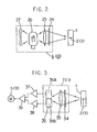
- F ig. 2 and 3 illustrate the particulars of the projectors 6, 10 and the optics 7, 11.
- the projectors 6, 10 are each constructed, as shown in F ig. 2, of an ultraviolet lamp 26 provided as a light source, a combination of a concave mirror 27 and a convex lens 25 which combination serves to irradiate efficiently the emission light rays from the lamp 26 upon the bench marks 2, 3 on the specimen 1 and a light filter 24 for intercepting and removing the visible rays from the ultraviolet lamp 26 thereby to irradiate the bench marks 2, 3 only with the ultraviolet rays.
- F ig. 2 an ultraviolet lamp 26 provided as a light source
- a combination of a concave mirror 27 and a convex lens 25 which combination serves to irradiate efficiently the emission light rays from the lamp 26 upon the bench marks 2, 3 on the specimen 1
- a light filter 24 for intercepting and removing the visible rays from the ultraviolet lamp 26 thereby to irradiate the bench marks 2, 3 only with the ultraviolet rays.
- the optics assemblies 7, 11 are, as shown in Fig. 3, each equipped with a filter 34 for removing the ultraviolet rays when receiving the luminescent rays emitted by the bench marks 2, 3 on the specimen 1, a convex lens 35 for condensing thereon the visible rays from which the ultraviolet rays are removed and a multi-element semiconductor detecotr 36 for detecting amount of the incident light thus condensed.
- the optics assemblies are constructed so as to collect only the visible rays on the convex lens 35 and to introduce them into the detector 36, whereby their reliability as a device is ensured.
- the multi-element semiconductor detector 36 assumes the form of two multi-element semiconductor detectors 36A, 36B in which the multi-element is equally divided into two.
- a mechanism is adopted in which the outputs of the multi-element semiconductor detectors 36A, 36B are amplified by respective amplifiers 37, 38 and then supplied to a differential amplifier 39 for amplification, and the amplified output in turn sets the balancing electric motors 5, 9 into revolution.
- the two bench marks 2, 3 marked on the specimen 1 as shown in Fig. 1 are first irradiated with ultraviolet rays from the projectors 6, 10 and only the bench marks are caused to emit luminescent lights.
- the luminescent light thus emitted is received by the optics assemblies 7, 11.
- the respective beams of the luminescent light of the bench marks are passed through the filters 34 housed in the optics assemblies (Cf. Fig. 3), by which the ultraviolet rays are absorbed and removed, and only the resulting visible rays are collected by the convex lens 35 and introduced into the multi-element semiconductor detectors 36.
- the respective visible rays are detected with the detectors 36 to transmit analogue signals which, after undergoing amplification action in the optics, operate to rotate the balancing electric motors 5, 9.
- both the transmission signals from the elongation detectors 4, 8 are supplied in this way, the difference between both signals is obtained by the operation of the arithmetic unit 12 as elongation differences. Consequently, elongations between both bench marks 2, 3 can be automatically measured.
- the tensile tester of this invention enables measurement of elongations of specimens with high accuracy by virtue of the combination of the ultraviolet projector and the optic incorporating the detector as well as provision of further mechanical elements.
- the tensile tester according to the tensile tester of this invention is conducted by using an ultraviolet lamp as a light source of the projector, submitting only the bench marks on a specimen beforehand marked to emission, detecting the luminescent light rays thus emitted with the detectors, causing the arrangements of paired projector and optics to pursue the bench marks following the detection, and measuring elongations between the bench marks by the provision of the elongation detectors and the arithmetic unit.
- the pursuit mechanism enable the projector-optics arrangements to perpetually pursue automatically with high accuray the targets of the bench marks.
- the tensile tester is provided with an apparatus capable of measuring elongations of a wide variety of specimens in non-contact manner and with high accuracy by irradiating the bench marks on a previously marked specimen with the aid of an ultraviolet lamp to cause emission only from the bench marks and detecting the luminescent light rays thus emitted.
Landscapes
- Physics & Mathematics (AREA)
- General Physics & Mathematics (AREA)
- Health & Medical Sciences (AREA)
- Life Sciences & Earth Sciences (AREA)
- Chemical & Material Sciences (AREA)
- Analytical Chemistry (AREA)
- Biochemistry (AREA)
- General Health & Medical Sciences (AREA)
- Immunology (AREA)
- Pathology (AREA)
- Investigating Strength Of Materials By Application Of Mechanical Stress (AREA)
Applications Claiming Priority (2)
| Application Number | Priority Date | Filing Date | Title |
|---|---|---|---|
| JP110535/83 | 1983-06-20 | ||
| JP58110535A JPS603537A (ja) | 1983-06-20 | 1983-06-20 | ゴム・プラスチック用引張試験機 |
Publications (2)
| Publication Number | Publication Date |
|---|---|
| EP0129242A1 true EP0129242A1 (fr) | 1984-12-27 |
| EP0129242B1 EP0129242B1 (fr) | 1987-05-20 |
Family
ID=14538269
Family Applications (1)
| Application Number | Title | Priority Date | Filing Date |
|---|---|---|---|
| EP84106992A Expired EP0129242B1 (fr) | 1983-06-20 | 1984-06-19 | Appareil d'essai de traction |
Country Status (4)
| Country | Link |
|---|---|
| US (1) | US4605857A (fr) |
| EP (1) | EP0129242B1 (fr) |
| JP (1) | JPS603537A (fr) |
| DE (1) | DE3463843D1 (fr) |
Cited By (7)
| Publication number | Priority date | Publication date | Assignee | Title |
|---|---|---|---|---|
| EP0237835A3 (en) * | 1986-03-17 | 1989-07-19 | Mitec Moderne Industrietechnik Gmbh | Measuring device measuring device |
| FR2695207A1 (fr) * | 1992-09-01 | 1994-03-04 | Aerospatiale | Installation pour mesurer la déformation in situ de chapelets d'éprouvettes soumis à des essais de fluage de longue durée. |
| EP0694756A3 (fr) * | 1994-07-27 | 1997-05-07 | Shimadzu Corp | Mesure d'élongation avec un extensomètre laser sans contact |
| DE19620419A1 (de) * | 1996-05-21 | 1997-11-27 | Ettemeyer Gmbh & Co Mes Und Pr | Verfahren zur berührungslosen und markierungsfreien Messung von Verschiebungen |
| CN103063174A (zh) * | 2011-10-20 | 2013-04-24 | 上海力远计算机科技有限公司 | 无线预应力张拉伸长量测量装置 |
| CN105203041A (zh) * | 2015-09-21 | 2015-12-30 | 南昌航空大学 | 一种宽带荧光积分强度比测量应变的方法 |
| GB2618524A (en) * | 2022-05-02 | 2023-11-15 | Imetrum Ltd | Non-contact deformation monitoring system |
Families Citing this family (15)
| Publication number | Priority date | Publication date | Assignee | Title |
|---|---|---|---|---|
| JPS62287941A (ja) * | 1986-06-02 | 1987-12-14 | Mitsubishi Electric Corp | 放電加工装置 |
| US4754134A (en) * | 1987-04-16 | 1988-06-28 | Shin Meiwa Industry Co., Ltd. | Method of and apparatus for inspecting a stripped wire end |
| DE3720303C2 (de) * | 1987-06-19 | 1993-09-30 | Schenck Ag Carl | Probeneinspannvorrichtung für Prüfmaschinen |
| DE3720248A1 (de) * | 1987-06-19 | 1989-01-05 | Schenck Ag Carl | Verfahren und anordnung zur messung von verformungen an proben oder pruefkoerpern in pruefmaschinen |
| DE3740227C2 (de) * | 1987-11-27 | 1994-03-24 | Schenck Ag Carl | Verfahren und Vorrichtung zur Messung von Verformungen an Proben oder Prüfkörpern in Prüfmaschinen |
| EP0320122A3 (fr) * | 1987-11-30 | 1992-04-29 | United Kingdom Atomic Energy Authority | Appareil et procédé pour contrôle de position |
| JPH02106250A (ja) * | 1988-10-14 | 1990-04-18 | Hitachi Seiki Co Ltd | Nc工作機械メインテナンスのための潤滑油管理方法とリトライカウント方法 |
| JP2716304B2 (ja) * | 1991-12-20 | 1998-02-18 | 本田技研工業株式会社 | Nc装置の工具接合異常処理方法 |
| US5383776A (en) * | 1992-12-31 | 1995-01-24 | Hoechst Celanese Corporation | Apparatus for analyzing polymer defects |
| DE19520371B4 (de) * | 1995-06-02 | 2005-06-02 | Dantec Ettemeyer Gmbh | Verfahren und Vorrichtung zur Vergrößerung des Meßbereichs von Speckle-Meßsystemen bei Dehnungsmessungen an einer Probe |
| JP3373831B2 (ja) * | 2000-01-19 | 2003-02-04 | 岸本産業株式会社 | 試験片の伸び測定方法及び装置 |
| CN102288496A (zh) * | 2011-08-15 | 2011-12-21 | 中核苏阀横店机械有限公司 | 一种标距仪 |
| KR102798449B1 (ko) * | 2020-03-04 | 2025-04-22 | 주식회사 엘지에너지솔루션 | 박막 시편의 물성 평가방법 및 인장시험 테스트용 박막 시편 |
| CN112361941A (zh) * | 2020-11-09 | 2021-02-12 | 天津正丽科技有限公司 | 一种快速定性检测隐形牙齿矫治器变形的装置及方法 |
| KR102522830B1 (ko) * | 2021-10-13 | 2023-04-17 | 박용수 | 시험편과 일체화된 신장 측정용 돌출눈금을 가진 인장시험용 고무 시험편 |
Citations (3)
| Publication number | Priority date | Publication date | Assignee | Title |
|---|---|---|---|---|
| US3435231A (en) * | 1965-08-10 | 1969-03-25 | Instron Ltd | Optical means for following the relative movement of two marks on a specimen during tensile testing |
| GB1416541A (en) * | 1972-11-06 | 1975-12-03 | Wallace Co Ltd H W | Method and apparatus for following the motion of a datum mark |
| GB1553101A (en) * | 1976-04-30 | 1979-09-19 | Iwamoto Seisakusho Co Ltd | Automatic tensile test apparatus |
Family Cites Families (3)
| Publication number | Priority date | Publication date | Assignee | Title |
|---|---|---|---|---|
| US2989690A (en) * | 1959-04-29 | 1961-06-20 | Gen Electric | Elongation, length, and velocity gage |
| US3559253A (en) * | 1968-11-05 | 1971-02-02 | Cluett Peabody & Co Inc | Textile web shrinking apparatus comprising means for measuring distance between index marks on the web |
| JPS4850084U (fr) * | 1971-10-12 | 1973-06-30 |
-
1983
- 1983-06-20 JP JP58110535A patent/JPS603537A/ja active Granted
-
1984
- 1984-06-08 US US06/618,607 patent/US4605857A/en not_active Expired - Lifetime
- 1984-06-19 EP EP84106992A patent/EP0129242B1/fr not_active Expired
- 1984-06-19 DE DE8484106992T patent/DE3463843D1/de not_active Expired
Patent Citations (3)
| Publication number | Priority date | Publication date | Assignee | Title |
|---|---|---|---|---|
| US3435231A (en) * | 1965-08-10 | 1969-03-25 | Instron Ltd | Optical means for following the relative movement of two marks on a specimen during tensile testing |
| GB1416541A (en) * | 1972-11-06 | 1975-12-03 | Wallace Co Ltd H W | Method and apparatus for following the motion of a datum mark |
| GB1553101A (en) * | 1976-04-30 | 1979-09-19 | Iwamoto Seisakusho Co Ltd | Automatic tensile test apparatus |
Cited By (9)
| Publication number | Priority date | Publication date | Assignee | Title |
|---|---|---|---|---|
| EP0237835A3 (en) * | 1986-03-17 | 1989-07-19 | Mitec Moderne Industrietechnik Gmbh | Measuring device measuring device |
| FR2695207A1 (fr) * | 1992-09-01 | 1994-03-04 | Aerospatiale | Installation pour mesurer la déformation in situ de chapelets d'éprouvettes soumis à des essais de fluage de longue durée. |
| EP0694756A3 (fr) * | 1994-07-27 | 1997-05-07 | Shimadzu Corp | Mesure d'élongation avec un extensomètre laser sans contact |
| DE19620419A1 (de) * | 1996-05-21 | 1997-11-27 | Ettemeyer Gmbh & Co Mes Und Pr | Verfahren zur berührungslosen und markierungsfreien Messung von Verschiebungen |
| CN103063174A (zh) * | 2011-10-20 | 2013-04-24 | 上海力远计算机科技有限公司 | 无线预应力张拉伸长量测量装置 |
| CN105203041A (zh) * | 2015-09-21 | 2015-12-30 | 南昌航空大学 | 一种宽带荧光积分强度比测量应变的方法 |
| CN105203041B (zh) * | 2015-09-21 | 2017-11-10 | 南昌航空大学 | 一种宽带荧光积分强度比测量应变的方法 |
| GB2618524A (en) * | 2022-05-02 | 2023-11-15 | Imetrum Ltd | Non-contact deformation monitoring system |
| GB2618524B (en) * | 2022-05-02 | 2025-02-05 | Imetrum Ltd | Non-contact deformation monitoring system |
Also Published As
| Publication number | Publication date |
|---|---|
| DE3463843D1 (en) | 1987-06-25 |
| US4605857A (en) | 1986-08-12 |
| JPS603537A (ja) | 1985-01-09 |
| EP0129242B1 (fr) | 1987-05-20 |
| JPH0220930B2 (fr) | 1990-05-11 |
Similar Documents
| Publication | Publication Date | Title |
|---|---|---|
| EP0129242B1 (fr) | Appareil d'essai de traction | |
| US5319200A (en) | Rapid near-infrared measurement of nonhomogeneous samples | |
| EP0169657B1 (fr) | Détecteur de l'angle d'un arbre | |
| EP0903572A3 (fr) | Dispositif pour détecter des salissures sur une fenêtre | |
| US4650334A (en) | Optical straightness gauge and method | |
| US3775013A (en) | Optical turbidimeter apparatus | |
| US3761179A (en) | Mirror testing apparatus | |
| JPS60171405A (ja) | 偏芯量の自動検査装置 | |
| GB2123139A (en) | A device for the fast measurement of the gloss of a surface | |
| JP2002214097A (ja) | ゴム・プラスチックの引張試験方法 | |
| SU1384218A3 (ru) | Способ сравнени оптических свойств двух образцов | |
| US3985454A (en) | Window defect planar mapping technique | |
| US2986066A (en) | Polarimetric apparatus | |
| FI70647B (fi) | Apparat foer testning av ett prov av fibrer eller filament | |
| PT77272B (fr) | Procede et appareil de mesure de la brillance d'une couleur | |
| JPH02114146A (ja) | 構造部品や試験片における亀裂長さやひずみを測定する方法とその装置 | |
| KR870005265A (ko) | 단일 모우드 광학 섬유 모우드 휠드 반경 측정 방법 및 장치 | |
| US3713742A (en) | Scene auto-correlator | |
| JP3365881B2 (ja) | レンズの屈折率検査装置 | |
| JPS6228606A (ja) | 膜厚測定装置 | |
| SU1211603A1 (ru) | Устройство дл измерени перемещений | |
| SU1659794A1 (ru) | Способ определени индикатрисы рассе ни естественного излучени плоскими рассеивающими объектами | |
| SU473906A1 (ru) | Инфракрасный радиометр | |
| US4463259A (en) | Method and apparatus for measuring the displacement of a radiation-restrictive mark, as in a surveying instrument | |
| SU769323A1 (ru) | Устройство дл определени класса шероховатости полированных металлических поверхностей издели |
Legal Events
| Date | Code | Title | Description |
|---|---|---|---|
| PUAI | Public reference made under article 153(3) epc to a published international application that has entered the european phase |
Free format text: ORIGINAL CODE: 0009012 |
|
| AK | Designated contracting states |
Designated state(s): DE FR GB |
|
| 17P | Request for examination filed |
Effective date: 19841210 |
|
| 17Q | First examination report despatched |
Effective date: 19860226 |
|
| GRAA | (expected) grant |
Free format text: ORIGINAL CODE: 0009210 |
|
| AK | Designated contracting states |
Kind code of ref document: B1 Designated state(s): DE FR GB |
|
| ET | Fr: translation filed | ||
| REF | Corresponds to: |
Ref document number: 3463843 Country of ref document: DE Date of ref document: 19870625 |
|
| PLBE | No opposition filed within time limit |
Free format text: ORIGINAL CODE: 0009261 |
|
| STAA | Information on the status of an ep patent application or granted ep patent |
Free format text: STATUS: NO OPPOSITION FILED WITHIN TIME LIMIT |
|
| 26N | No opposition filed | ||
| PGFP | Annual fee paid to national office [announced via postgrant information from national office to epo] |
Ref country code: GB Payment date: 19950616 Year of fee payment: 12 |
|
| PGFP | Annual fee paid to national office [announced via postgrant information from national office to epo] |
Ref country code: DE Payment date: 19950627 Year of fee payment: 12 |
|
| PGFP | Annual fee paid to national office [announced via postgrant information from national office to epo] |
Ref country code: FR Payment date: 19950629 Year of fee payment: 12 |
|
| PG25 | Lapsed in a contracting state [announced via postgrant information from national office to epo] |
Ref country code: GB Effective date: 19960619 |
|
| GBPC | Gb: european patent ceased through non-payment of renewal fee |
Effective date: 19960619 |
|
| PG25 | Lapsed in a contracting state [announced via postgrant information from national office to epo] |
Ref country code: FR Effective date: 19970228 |
|
| PG25 | Lapsed in a contracting state [announced via postgrant information from national office to epo] |
Ref country code: DE Effective date: 19970301 |
|
| REG | Reference to a national code |
Ref country code: FR Ref legal event code: ST |