EP0129352B1 - Appareil à tréfiler - Google Patents
Appareil à tréfiler Download PDFInfo
- Publication number
- EP0129352B1 EP0129352B1 EP84303595A EP84303595A EP0129352B1 EP 0129352 B1 EP0129352 B1 EP 0129352B1 EP 84303595 A EP84303595 A EP 84303595A EP 84303595 A EP84303595 A EP 84303595A EP 0129352 B1 EP0129352 B1 EP 0129352B1
- Authority
- EP
- European Patent Office
- Prior art keywords
- wire
- frame
- carriage
- clamp
- die
- Prior art date
- Legal status (The legal status is an assumption and is not a legal conclusion. Google has not performed a legal analysis and makes no representation as to the accuracy of the status listed.)
- Expired
Links
Images


Classifications
-
- B—PERFORMING OPERATIONS; TRANSPORTING
- B21—MECHANICAL METAL-WORKING WITHOUT ESSENTIALLY REMOVING MATERIAL; PUNCHING METAL
- B21C—MANUFACTURE OF METAL SHEETS, WIRE, RODS, TUBES, PROFILES OR LIKE SEMI-MANUFACTURED PRODUCTS OTHERWISE THAN BY ROLLING; AUXILIARY OPERATIONS USED IN CONNECTION WITH METAL-WORKING WITHOUT ESSENTIALLY REMOVING MATERIAL
- B21C1/00—Manufacture of metal sheets, wire, rods, tubes or like semi-manufactured products by drawing
- B21C1/16—Metal drawing by machines or apparatus in which the drawing action is effected by means other than drums, e.g. by a longitudinally-moved carriage pulling or pushing the work or stock for making metal sheets, rods or tubes
- B21C1/18—Metal drawing by machines or apparatus in which the drawing action is effected by means other than drums, e.g. by a longitudinally-moved carriage pulling or pushing the work or stock for making metal sheets, rods or tubes from stock of limited length
Definitions
- This invention relates to an apparatus for drawing a wire to reduce a cross-section thereof.
- One conventional wire drawing apparatus 10 shown in Fig. 1 comprises a horizontal elongated frame 11 having front and rear ends 11 a and 11b, such wire drawing apparatus being commonly referred to as “drawbench” in the trade.
- a drawing die 12 is detachably mounted on the top 11 c of the frame 11 and disposed intermediate opposite ends thereof.
- a carriage 13 is mounted on the top 11c of the frame 11 for reciprocable movement along a drawing section 11d of the frame 11 extending between the drawing die 12 and the front end 11 a.
- a chuck 14 is fixedly secured to one end of the carriage 13 directed toward the drawing die 12.
- a hook member 15 is mounted on the other end of the carriage 13 for vertical pivotal movement.
- a drive sprocket 16 is rotatably mounted on the front end 11 a of the frame 11 while a driven sprocket 17 is rotatably mounted on the frame 11 at a position below the drawing die 12.
- a plurality of guide rollers 18 are rotatably mounted on the frame 11 and disposed between the drive and driven sprockets 16 and 17.
- An endless chain 20 extends around the drive and driven sprockets 16 and 17 and is held under an appropriate tension by the guide rollers 18.
- the drive sprocket 17 is operatively connected to a motor (not shown) for being driven for rotation.
- the endless chain 20 is composed of two pairs of parallel, longitudinally disposed links 20a and transverse pins 20b interconnecting the links 20a, as shown in Fig. 2.
- the hook member 15 is adapted to be engaged with a selected one of the pins 20b of the endless chain 20.
- one end of the wire 22 is first processed into a tapered shape, and the wire 22 is placed on the top 11c of a delivery section 11 of the frame 11 with the tapered end passed through the hole of the drawing die 12. Then, the tapered end passing through the hole of the drawing die 12 is clamped by the chuck 14. Then, the hook member 15 is pivotally moved downwardly to engage the pin 20b of the endless chain 20 disposed below the hook member 15, as shown in Fig. 3.
- the endless chain 20 is driven by the motor to move around the drive and driven sprockets 16 and 17 to move the carriage 13 along the frame 11 toward the front end 11a a thereof, so that the wire 22 is pulled through the drawing die 12 to reduce the diameter thereof at a predetermined rate.
- the wire 22 is detached from the chuck 14. Then, the drawing die 12 is replaced by another die having a hole smaller in diameter than the hole of the die 12. Then, one end of the wire 22 is again processed to reduce its diameter so that the reduced or tapered end can be passed through the drawing die.
- the second drawing operation is carried out according to the above- mentioned procedure. Usually, the wire is drawn several times in this manner, using drawing dies having holes of different diameters. Thus, the wire is reduced in diameter or cross-section at a predetermined rate each time the drawing operation is carried out.
- the drawing operation When a wire having a diameter of 20 mm is to be reduced to a diameter of 4 mm at a reduction rate of 20%, the drawing operation must be carried out seven times, and each time the drawing operation is completed, the wire has to be transferred from the drawing section 11d to the delivery section He for the next drawing operation. This requires much time and is not efficient. In addition, the wire is liable to be damaged or bent during the transferring thereof. Further, with this conventional drawing apparatus, it is necessary that the delivery section 11 should have a length generally equal to that of the drawing section 11d. Thus, the frame 11 had to be twice the length of the finished wire. As a result, the wire drawing apparatus 10 has a substantially increased overall length and therefore is space-consuming.
- DE-A-2 549 725 and DE-C-77 616 disclose similar forms of known apparatus for drawing wire.
- the present invention seeks to provide a wire drawing apparatus which is substantially reduced in length, and does not require a wire to be transferred from the discharge side to the delivery side for a subsequent drawing operation each time the drawing operation is completed, thereby preventing the wire from being damaged or bent during the drawing operation.
- an apparatus for drawing a wire which comprises an elongated frame; a carriage mounted on the frame for movement therealong; a chuck mounted on the frame at one end thereof for holding one end of the wire; a drawing die mounted on the carriage for passing the wire therethrough; actuating means operatively connected to the carriage for moving it along the frame away from the chuck to move the die along the wire so as to reduce a cross-section of the wire; a plurality of clamp devices mounted on the frame and spaced along the length thereof for holding the wire; a plurality of drive devices mounted adjacent to the clamp devices, respectively, each of the drive devices being operatively connected to a respective one of the clamp devices for moving it into and out of an operative position sensors mounted adjacent to the clamp devices, respectively, each of the position sensors being operatively connected to a respective one of the drive devices and sensing the approaching of the carriage toward a respective one of the clamp devices disposed adjacent thereto to produce a sensing signal in response to which the drive device is operated to move the clamp
- wire means both a wire of the solid type and a hollow elongated element.
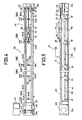
- a wire drawing apparatus 30 shown in Figs. 4 and 5 comprises a horizontal elongated frame 31 which includes front and rear end members 31a and 31b and a pair of parallel spaced upper rails 32 and 32 extending horizontally between the front and rear end members 31a and 31b.
- An upright support member 33 is fixedly mounted on the rear end member 31b.
- a chuck 34 is fixedly mounted on one surface of the support member 33 directed toward the front end member 31a, the chuck 34 being adapted to hole one end of a wire 22.
- a carriage 35 is mounted on the frame 31 for reciprocable movement therealong between the chuck 34 and the front end member 31a.
- each of the upper rails 32 and 32 has an H-shaped cross-section.
- a pair of guide rails 36 and 36 of a channel-shaped cross-section are fixedly secured to the opposed sides of the H-shaped rails 32 and 32.
- the carriage 35 includes a body 35a, and front and rear axles 37 each mounted on the body 35a and supporting wheels 38 at opposite ends therof, the wheels 38 being disposed in rolling engagement with the guide rails 36 and 36.
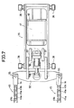
- a pair of drive sprockets 40 and 40 are rotatably mounted on the front end member 31a and are operatively connected to an electric motor 41 for being driven for rotation. Also, a pair of driven sprockets 42 and 42 are rotatably mounted on the rear end member 31 b.
- the frame 31 also includes a pair of parallel spaced lower rails 44 extending horizontally between the front and rear end members 31 a and 31 b.
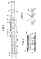
- a pair of endless chains 45 and 45 each extends around the drive and driven sprockets 40 and 42 and is guided by the upper and lower rails 32 and 44. Each of the endless chains 45 and 45 is composed of longitudinally disposed links 45a and transverse pins 45b as best shown in Fig. 7.
- a drawing die 47 is detachably mounted on the carriage 35 through a die holder 48, and has a die hole 47a for passing the wire 22 therethrough to draw it.
- the die hole 47a is tapered in a direction toward the chuck 34 and has an axis disposed in alignment with the axis of the chuck 34 and disposed in parallel with the longitudinal axis of the frame 31. Also, the axis of the die hole 47a passes perpendicularly through the axes of the transverse pins 45b of that portion of each endless chain 45 riding on the upper rail 32.
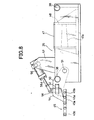
- a pair of parallel spaced links 50 and 50 are mounted at one end thereof on one end of the carriage 35 by pins 51 for pivotal movement thereabout.
- An arm 52 is fixedly secured to the other ends of the links 50 and 50, the arm 52 being disposed transversely of the pair of endless chains 45 and 45.
- a pair of hook members 54 and 54 are pivotally mounted on the opposite ends of the arm 52 by pins 55 and 55 for pivotal movement thereabout.
- a pneumatic cylinder 56 is mounted on the carriage 35 through a pair of brackets 57 and 57.
- a piston rod 56a of the pneumatic cylinder 56 is pivotally connected to the arm 52 through a connecting member 58. With this construction, the pneumatic cylinder 56 is actuated to extend the piston rod 56 to angularly move the arms 52 counterclockwise (Fig. 8) about the pins 51 and 51 so that each of the hook members 54 and 54 is caused to engage one of the transverse pins 45b of the endless chain 45.
- a plurality of elevating or drive devices 59A to 59N in the form of a pneumatic cylinder are mounted on one of the lower rails 44 of the frame 31 and are spaced along the length of the frame 31.
- the pneumatic cylinders 59A to 59N are disposed substantially perpendicular to the path of travel of the drawing die 47 carried by the carriage 35.
- Clamp devices 61A to 61N are mounted on distal ends of piston rods 60A to 60N of the pneumatic cylinders 59A to 59N, respectively, through mounting members 62.
- Each of the clamp devices 61A to 61 N is moved between a lower or inoperative position indicated in a solid line in Fig. 6 and an upper or operative position indicated in phantom in Fig. 6 by a respective one of the pneumatic cylinders 59A to 59N.
- Each clamp device when in its upper position, is disposed in the path of the travel of the carriage 35 for holding the wire 22, as hereinafter more fully described.
- a plurality of position sensors 64A to 64N are mounted on one of the upper rails 32 and 32 and are disposed adjacent to the pneumatic cylinders 59A to 59N, respectively, each position sensor being in the form of photosensor.
- Each position sensor serves to detect the approaching of the carriage 35 toward a respective one of the clamp devices 61A to 61 N disposed adjacent to it, so that the clamp device is retracted from the path of travel of the carriage 35 by the associated one of the pneumatic cylinders 59A to 59N to prevent the associated clamp device from interfering with the carriage 35 moving along the upper rails 32 and 32.
- each of the pneumatic cylinders 59A to 59N is actuated to retract its piston rod 60A to 60N through a control means (not shown) in response to a sensing signal from the associated one of the position sensors 64A to 64N disposed adjacent to and rearwardly of it, thereby bringing the associated clamp device into its lower position.
- each of the pneumatic cylinders 59A to 59N is actuated to extend its piston rod 60A to 60N through the control means in response to a sensing signal from the one of the position sensors 64A to 64N disposed next to, i.e., forwardly of it, thereby bringing the retracted clamp device into its upper position.
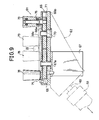
- each clamp device 61 (61A to 61 N) includes a hollow body 66 of a rectangular shape connected to the piston rod 60 (60A to 60N) of the pneumatic cylinder 59 (59A to 59N) through the mounting member 62, the body comprising a pair of horizontally-disposed upper and lower plates 66a and 66b and a horizontally-disposed support member 66c for supporting the wire 22.
- a pneumatically-operated rotary actuator 67 is mounted on the lower plate 66b of the body 66 and has an output shaft 67a extending through the lower and upper plates 66b and 66a.
- a first gear 68 is received in the hollow body 66 and fixedly mounted on the output shaft 67a of the rotary actuator 67 in coaxial relation thereto.
- a shaft 70 extends through and is fixed to the lower and upper plates 66b and 66a of the body 66.
- a second gear 71 is received in the hollow body 66 and rotatably mounted on the shaft 70 in coaxial relation thereto.
- the first and second gears 68 and 71 are in mesh with each other and are disposed horizontally.
- a pair of arcuate slots 73 and 74 are formed through the upper plate 66a and disposed symmetrically with respect to the axis of the hole 47a of the drawing die 47 when the clamp device 61 is in its upper position.
- a vertical pin 75 is fixedly mounted on the first gear 68 in eccentric relation to the output shaft 67a and is received in the arcuate slot 73 for movement therealong.
- another vertical pin 76 is fixedly mounted on the second gear 71 in eccentric relation to the shaft 70 and is received in the arcuate slot 74 for movement therealong.
- a roll 78 is rotatably mounted on the pin 75 in coaxial relation thereto while another roll 79 is rotatably mounted on the pin 76 in coaxial relation thereto, each of the rolls 78 and 79 tapering downwardly toward the upper plate 66a.
- the rotary actuator 67 is actuated to angularly move the output shaft 67a about its axis so that the rolls 78 and 79 are moved along the respective arcuate slots 73 and 74 toward and away from each other.
- the rotary actuator 67 is actuated to move the rolls 78 and 79 toward each other to hold the wire 22 therebetween when the clamp device 61 is moved to its upper position.
- the rotary actuator 67 is actuated to move the rolls 78 and 79 out of engagement with the wire 22 immediately before the clamp device 61 is moved to its lower position. This operation of the rotary actuator 67 is controlled through the control means in response to the sensing signals from the position sensors 64, as hereinafter more fully described.
- a plurality of horizontal elongated receptacles 80 are mounted on the lower rails 44 and 44 and spaced along the length of the frame 31 for receiving the wire 22 if it is cut during the drawing operation.
- Each receptacle 80 is mounted on the lower rails 44 and 44 through a pair of pivotal links 81 and 81 for being vertically adjusted.
- one end of the wire 22 is first processed into a tapered shape.
- the carriage 35 is located immediately adjacent to the chuck 34.
- the clamp device 61A is held in its lower position so that it will not interfere with the carriage 35.
- the taper end of the wire 22 is passed through the hole 47a of the drawing die 47 and is clamped by the chuck 34.
- the clamp devices 61 B to 61 N are moved to their upper positions.
- the pneumatic cylinder 56 is operated to angularly move the arm 52 in a counterclockwise direction (Fig. 8) so that the pair of hook members 54 and 54 are caused to engage the transverse pins 54b of the respective endless chains 45 and 45.
- the endless chains 45 and 45 are driven by the motor 41 through the drive sprocket 40 to move the carriage 35 along the upper rails 32 and 32 toward the front end member 31a, so that the drawing die 47 moves along the wire 22 to reduce the diameter thereof at a predetermined rate.
- each clamp device 61 is moved to its lower position by the associated pneumatic cylinder 59 when the carriage 35 approaches it, and is returned to its upper position by the pneumatic cylinder 59 after the carriage 35 moves past it. More specifically, soon after the carriage 35 starts moving along the upper rails 32 and 32 toward the front end member 31 a, the position sensor 64B detects the approaching of the carriage 35 toward the clamp device 59B, so that the rotary actuator 67 of the clamp device 59B is actuated to bring the pair of rolls 78 and 79 out of engagement with the wire 22. Subsequently, the clamp device 59B is moved to its lower position by the pneumatic cylinder 59B so as not to interfere with the moving carriage 35.
- the carriage 35 continues to move along the upper rails 32 and 32, and the next position sensor 64C detects the approaching of the carriage 35 toward the clamps device 61 C, so that the pneumatic cylinder 59B is actuated to extend its piston rod 60B to bring the clamp device 61 B to its upper position, and that the rotary actuator 67 of the clamp device 61B is actuated to bring the rolls 78 and 79 into engagement with the wire 22 to hold it therebetween.
- the position sensor 64C detects the approaching of the carriage 35
- the rotary actuator 67 of the clamp device 61C is actuated to bring the rolls 78 and 79 out of engagement with the wire 22, and that the pneumatic cylinder 59C is actuated to move the clamp device 61 C to its lower position.
- the position sensors 64D to 64N sequentially detect the approaching of the carriage 35 to operate the clamp devices 61 D to 61 N and their associated rotary actuators 67 in the manner described above.
- the pneumatic cylinder 56 is actuated to retract its piston rod 56a so that the hook members 54 and 54 are angularly moved about the pins 51 and 51 and disengaged from the respective transverse pins 45b and 45b of the endless chains 45 and 45. Then, the carriage 35 is moved back along the rails 32 and 32 toward the rear end member 31 b, and the drawing die 47 is detached from the die holder 48 and replaced by another die having a die hole smaller in diameter than the hole 47a of the drawing die 47. Then, a second drawing operation is carried out according to the procedure mentioned above. The wire 22 is drawn several times in this manner, using a plurality of drawing dies having die holes of different diameters until the wire 22 is reduced to a desired diameter.
- the wire 22 Since the wire 22 is supported by the clamp devices 61 during the drawing operation, the wire 22 is not subjected to bending and vibration. Therefore, the drawn wire 22 does not have marks on its surface which are caused by the drawing die 47 if the wire 22 is not held in alignment with the hole 47a of the die 47.
- the axes of the transverse pins 45b of those portions of the endless chains 45, 45 pass perpendicularly through the axis of the hole 47a of the drawing die 47 and the axis of the chuck 34.
- the pulling force, applied to the drawing die 47 by the endless chains 45 and 45 through the hook members 54 and 54, is exerted on the common axis of the chuck 34 and die hole 47a. Therefore, the die 47 will not cause marks on the surface of the drawn wire.
- each upper rail 32 may not always be completely smooth and be slightly rugged at some locations, in which case the die 47 is slightly moved vertically when the carriage 35 pass such rugged portions of the rails 32 and 32.
- the downwardly-tapering rolls 78 and 79 permit the wire 22 to follow this slight vertical movement of the drawing die 47 since the rotary actuator 67 is pneumatically operated.
- the wire drawing apparatus 30 does not require a delivery section as is the case with the prior art wire drawing apparatus 10 and therefore can be reduced to a length generally equal to the length of the finished wire.
- the wire drawing apparatus 30 is quite space-saving.
- the wire does not need to be transferred to the delivery section each time the drawing operation is completed. Therefore, the drawing operation can be carried out quite efficiently. Further, since it is not necessary to transfer the wire during the successive drawing operations, the wire can be prevented from being damaged bent.
Landscapes
- Engineering & Computer Science (AREA)
- Mechanical Engineering (AREA)
- Metal Extraction Processes (AREA)
Claims (5)
Applications Claiming Priority (6)
| Application Number | Priority Date | Filing Date | Title |
|---|---|---|---|
| JP10382183A JPS59229225A (ja) | 1983-06-10 | 1983-06-10 | 線材の引き抜き加工装置 |
| JP103822/83 | 1983-06-10 | ||
| JP103821/83 | 1983-06-10 | ||
| JP10382283A JPS59229226A (ja) | 1983-06-10 | 1983-06-10 | 線材の引き抜き加工装置 |
| JP10607783A JPS59232613A (ja) | 1983-06-14 | 1983-06-14 | 線材の引き抜き加工装置 |
| JP106077/83 | 1983-06-14 |
Publications (3)
| Publication Number | Publication Date |
|---|---|
| EP0129352A2 EP0129352A2 (fr) | 1984-12-27 |
| EP0129352A3 EP0129352A3 (en) | 1985-06-26 |
| EP0129352B1 true EP0129352B1 (fr) | 1988-05-18 |
Family
ID=27310084
Family Applications (1)
| Application Number | Title | Priority Date | Filing Date |
|---|---|---|---|
| EP84303595A Expired EP0129352B1 (fr) | 1983-06-10 | 1984-05-29 | Appareil à tréfiler |
Country Status (3)
| Country | Link |
|---|---|
| US (1) | US4578972A (fr) |
| EP (1) | EP0129352B1 (fr) |
| DE (1) | DE3471267D1 (fr) |
Families Citing this family (1)
| Publication number | Priority date | Publication date | Assignee | Title |
|---|---|---|---|---|
| JPH07208999A (ja) * | 1994-01-20 | 1995-08-11 | Murata Mfg Co Ltd | 振動子の製造方法 |
Family Cites Families (10)
| Publication number | Priority date | Publication date | Assignee | Title |
|---|---|---|---|---|
| DE77616C (de) * | H. dollmann, Birmingham, Warwickshire, Engl | Ziehbank zum gleichzeitigen Ziehen mehrerer Arbeitsstücke | ||
| US2264688A (en) * | 1940-02-02 | 1941-12-02 | Nathan H Wolf | Tube drawing machine |
| US2767829A (en) * | 1952-07-07 | 1956-10-23 | Hallden Machine Company | Apparatus for drawing rod stock |
| FR1069923A (fr) * | 1952-09-24 | 1954-07-13 | Rheinische Rohrenwerke Ag | Banc d'étirage pour l'étirage à froid ou à chaud de tubes ou de barres |
| GB830485A (en) * | 1957-07-08 | 1960-03-16 | Norton Co Ltd Sir James Farmer | Improvements relating to drawbenches |
| US3116832A (en) * | 1959-09-23 | 1964-01-07 | Light Metals Corp | Method and control apparatus for pulling extrusions from dies |
| US3238752A (en) * | 1964-10-12 | 1966-03-08 | Titanium Metals Corp | Tube reducing apparatus |
| US3668910A (en) * | 1970-10-06 | 1972-06-13 | Granco Equipment | Extrusion handling apparatus |
| SU435026A1 (ru) * | 1972-07-31 | 1974-07-05 | Волочильный стан | |
| DE2549725A1 (de) * | 1975-11-06 | 1977-05-18 | Kabel Metallwerke Ghh | Verfahren zum herstellen nahtloser metallrohre |
-
1984
- 1984-05-29 DE DE8484303595T patent/DE3471267D1/de not_active Expired
- 1984-05-29 EP EP84303595A patent/EP0129352B1/fr not_active Expired
- 1984-06-07 US US06/618,120 patent/US4578972A/en not_active Expired - Lifetime
Also Published As
| Publication number | Publication date |
|---|---|
| US4578972A (en) | 1986-04-01 |
| EP0129352A3 (en) | 1985-06-26 |
| EP0129352A2 (fr) | 1984-12-27 |
| DE3471267D1 (en) | 1988-06-23 |
Similar Documents
| Publication | Publication Date | Title |
|---|---|---|
| US5182932A (en) | Apparatus for bending steel bars to form concrete reinforcement elements | |
| US5515667A (en) | Device for forming a stack extending perpendicular to the standing, sequential printed sheets | |
| US6134932A (en) | Machine for bending or cambering a profile section, and bending head therefor | |
| CA2387861A1 (fr) | Procede et dispositifs pour former des tuyaux | |
| JPS6034211A (ja) | 電線定寸切断装置 | |
| JPH06220782A (ja) | ケーブル加工機のためのケーブル供給及び変更装置 | |
| US4331015A (en) | Tube bending machine with axially movable inner core | |
| US4766756A (en) | Continuous processing machine assembly for bending long rods or tubes | |
| US4578972A (en) | Apparatus for drawing wire | |
| US4766754A (en) | Continuous process for bending long rods or tubes | |
| US4860568A (en) | Tubular material drawing apparatus for manufacturing precision tube | |
| JP3262413B2 (ja) | ボビン交換装置を備えた両側作業式リング精紡機 | |
| EP0570830A1 (fr) | Embarreur de tour à mâchoires coulissantes | |
| CN100488652C (zh) | 用于轧件的进给装置和用于轧件进给的方法 | |
| CN118122916B (zh) | 一种钢筋网笼加工流水线 | |
| CN115744472B (zh) | 多工位收卷装置 | |
| CN117680996A (zh) | 一种隧道钢构件自动处理加工装置 | |
| CN117884505A (zh) | 一种型钢铰链衬套的生产线 | |
| EP0104955A2 (fr) | Dispositif et procédé pour le tréfilage | |
| JPH10249471A (ja) | 溶接された縦及び横棒からなる補強マツトを製造する装置 | |
| CN118712838B (zh) | 一种大平方线材的换向、待加工端位置调节机构及其加工方法 | |
| JPH01293920A (ja) | 曲げ加工装置 | |
| EP0082926A1 (fr) | Dispositif pour déplacer des pots de machine de préparation à la filature | |
| CN221368960U (zh) | 一种洗衣机线圈走料移载机构 | |
| EP0562837A1 (fr) | Embarreur automatique |
Legal Events
| Date | Code | Title | Description |
|---|---|---|---|
| PUAI | Public reference made under article 153(3) epc to a published international application that has entered the european phase |
Free format text: ORIGINAL CODE: 0009012 |
|
| AK | Designated contracting states |
Designated state(s): CH DE FR GB LI |
|
| PUAL | Search report despatched |
Free format text: ORIGINAL CODE: 0009013 |
|
| AK | Designated contracting states |
Designated state(s): CH DE FR GB LI |
|
| 17P | Request for examination filed |
Effective date: 19851025 |
|
| 17Q | First examination report despatched |
Effective date: 19861104 |
|
| GRAA | (expected) grant |
Free format text: ORIGINAL CODE: 0009210 |
|
| AK | Designated contracting states |
Kind code of ref document: B1 Designated state(s): CH DE FR GB LI |
|
| REF | Corresponds to: |
Ref document number: 3471267 Country of ref document: DE Date of ref document: 19880623 |
|
| ET | Fr: translation filed | ||
| PLBE | No opposition filed within time limit |
Free format text: ORIGINAL CODE: 0009261 |
|
| STAA | Information on the status of an ep patent application or granted ep patent |
Free format text: STATUS: NO OPPOSITION FILED WITHIN TIME LIMIT |
|
| 26N | No opposition filed | ||
| PGFP | Annual fee paid to national office [announced via postgrant information from national office to epo] |
Ref country code: FR Payment date: 19980511 Year of fee payment: 15 |
|
| PGFP | Annual fee paid to national office [announced via postgrant information from national office to epo] |
Ref country code: GB Payment date: 19980520 Year of fee payment: 15 |
|
| PGFP | Annual fee paid to national office [announced via postgrant information from national office to epo] |
Ref country code: DE Payment date: 19980608 Year of fee payment: 15 |
|
| PGFP | Annual fee paid to national office [announced via postgrant information from national office to epo] |
Ref country code: CH Payment date: 19980611 Year of fee payment: 15 |
|
| PG25 | Lapsed in a contracting state [announced via postgrant information from national office to epo] |
Ref country code: GB Free format text: LAPSE BECAUSE OF NON-PAYMENT OF DUE FEES Effective date: 19990529 |
|
| PG25 | Lapsed in a contracting state [announced via postgrant information from national office to epo] |
Ref country code: LI Free format text: LAPSE BECAUSE OF NON-PAYMENT OF DUE FEES Effective date: 19990531 Ref country code: CH Free format text: LAPSE BECAUSE OF NON-PAYMENT OF DUE FEES Effective date: 19990531 |
|
| REG | Reference to a national code |
Ref country code: CH Ref legal event code: PL |
|
| GBPC | Gb: european patent ceased through non-payment of renewal fee |
Effective date: 19990529 |
|
| PG25 | Lapsed in a contracting state [announced via postgrant information from national office to epo] |
Ref country code: FR Free format text: LAPSE BECAUSE OF NON-PAYMENT OF DUE FEES Effective date: 20000131 |
|
| PG25 | Lapsed in a contracting state [announced via postgrant information from national office to epo] |
Ref country code: DE Free format text: LAPSE BECAUSE OF NON-PAYMENT OF DUE FEES Effective date: 20000301 |
|
| REG | Reference to a national code |
Ref country code: FR Ref legal event code: ST |