EP0129465A2 - Spritzkopf für einen verformbaren Behälter - Google Patents
Spritzkopf für einen verformbaren Behälter Download PDFInfo
- Publication number
- EP0129465A2 EP0129465A2 EP84401172A EP84401172A EP0129465A2 EP 0129465 A2 EP0129465 A2 EP 0129465A2 EP 84401172 A EP84401172 A EP 84401172A EP 84401172 A EP84401172 A EP 84401172A EP 0129465 A2 EP0129465 A2 EP 0129465A2
- Authority
- EP
- European Patent Office
- Prior art keywords
- shutter
- cover
- cap
- container
- orifice
- Prior art date
- Legal status (The legal status is an assumption and is not a legal conclusion. Google has not performed a legal analysis and makes no representation as to the accuracy of the status listed.)
- Granted
Links
Images

Classifications
-
- B—PERFORMING OPERATIONS; TRANSPORTING
- B05—SPRAYING OR ATOMISING IN GENERAL; APPLYING FLUENT MATERIALS TO SURFACES, IN GENERAL
- B05B—SPRAYING APPARATUS; ATOMISING APPARATUS; NOZZLES
- B05B7/00—Spraying apparatus for discharge of liquids or other fluent materials from two or more sources, e.g. of liquid and air, of powder and gas
- B05B7/0018—Spraying apparatus for discharge of liquids or other fluent materials from two or more sources, e.g. of liquid and air, of powder and gas with devices for making foam
- B05B7/0025—Spraying apparatus for discharge of liquids or other fluent materials from two or more sources, e.g. of liquid and air, of powder and gas with devices for making foam with a compressed gas supply
- B05B7/0031—Spraying apparatus for discharge of liquids or other fluent materials from two or more sources, e.g. of liquid and air, of powder and gas with devices for making foam with a compressed gas supply with disturbing means promoting mixing, e.g. balls, crowns
- B05B7/0037—Spraying apparatus for discharge of liquids or other fluent materials from two or more sources, e.g. of liquid and air, of powder and gas with devices for making foam with a compressed gas supply with disturbing means promoting mixing, e.g. balls, crowns including sieves, porous members or the like
-
- B—PERFORMING OPERATIONS; TRANSPORTING
- B05—SPRAYING OR ATOMISING IN GENERAL; APPLYING FLUENT MATERIALS TO SURFACES, IN GENERAL
- B05B—SPRAYING APPARATUS; ATOMISING APPARATUS; NOZZLES
- B05B11/00—Single-unit hand-held apparatus in which flow of contents is produced by the muscular force of the operator at the moment of use
- B05B11/01—Single-unit hand-held apparatus in which flow of contents is produced by the muscular force of the operator at the moment of use characterised by the means producing the flow
- B05B11/04—Deformable containers producing the flow, e.g. squeeze bottles
- B05B11/042—Deformable containers producing the flow, e.g. squeeze bottles the spray being effected by a gas or vapour flow in the nozzle, spray head, outlet or dip tube
- B05B11/043—Deformable containers producing the flow, e.g. squeeze bottles the spray being effected by a gas or vapour flow in the nozzle, spray head, outlet or dip tube designed for spraying a liquid
-
- B—PERFORMING OPERATIONS; TRANSPORTING
- B05—SPRAYING OR ATOMISING IN GENERAL; APPLYING FLUENT MATERIALS TO SURFACES, IN GENERAL
- B05B—SPRAYING APPARATUS; ATOMISING APPARATUS; NOZZLES
- B05B7/00—Spraying apparatus for discharge of liquids or other fluent materials from two or more sources, e.g. of liquid and air, of powder and gas
- B05B7/02—Spray pistols; Apparatus for discharge
- B05B7/10—Spray pistols; Apparatus for discharge producing a swirling discharge
-
- B—PERFORMING OPERATIONS; TRANSPORTING
- B05—SPRAYING OR ATOMISING IN GENERAL; APPLYING FLUENT MATERIALS TO SURFACES, IN GENERAL
- B05B—SPRAYING APPARATUS; ATOMISING APPARATUS; NOZZLES
- B05B11/00—Single-unit hand-held apparatus in which flow of contents is produced by the muscular force of the operator at the moment of use
- B05B11/0005—Components or details
- B05B11/0027—Means for neutralising the actuation of the sprayer ; Means for preventing access to the sprayer actuation means
- B05B11/0032—Manually actuated means located downstream the discharge nozzle for closing or covering it, e.g. shutters
Definitions
- the present invention relates to a spraying device for a deformable container, of the type used in various industries, including those of cleaning products and toiletries, for spraying liquids of everyday consumption contained in a container made of a material flexible enough to be deformable by hand.
- a spraying device for a deformable container of the type used in various industries, including those of cleaning products and toiletries, for spraying liquids of everyday consumption contained in a container made of a material flexible enough to be deformable by hand.
- Such containers can thus be compressed by the user to create a pressure for expelling the liquid which they contain, through a tube immersed in the container, and then to inflate by elastic effect creating a depression which sucks in the liquid. air from outside the container.
- the invention relates, more particularly, to devices of this type which comprise a single orifice, formed through a rigid cover closing the container, both for expelling the liquid during spraying and for suctioning the liquid. air coming from outside.
- the spraying device according to the invention has, in fact, the main advantages of ensuring very good spraying quality, of avoiding operating variations coming from a more or less liquid level. high as the container becomes empty during use, to ensure rapid penetration of outside air into the container at the end of spraying and to increase the possibility and effectiveness of close repetitive sprays.
- the spraying device is characterized in that it comprises a shutter movable axially in the container between a spraying position and a suction position, relative to a rigid cover closing the container and comprising the liquid outlet and air suction orifice, said shutter supporting a closure element of the dip tube in its air suction position and comprising a cap having an extended face on the outside which cooperates in the spraying position with an inner face of the cover to form a nozzle for spraying liquid through said orifice.
- the closure element of the dip tube is made in one piece with the shutter cap and consists of an axial rod, possibly tubular, penetrating into a junction cup between the dip tube and the shutter until it is in sealed contact with this cup in said suction position.
- the shutter is made in two parts which slide one inside the other between two extreme positions and which carry, one the cap defining the nozzle in the spraying position, the other the closing element of the dip tube.
- the shutter it is advantageous for the shutter to have, both on the hood side (top) and on the dip tube side (bottom), large surfaces which can alternately receive either the pressure necessary to push it upwards in the spraying position, or the effects of the vacuum created inside the container when it is no longer compressed.
- the greatest role is played there, in the direction of a rapid movement of the shutter, by the cap of the shutter, insofar as it is situated between the orifice of the cover and the communication opening between the device and the interior of the container.
- the guide of the shutter relative to the fixed members of the device, in particular the cover closing the container is preferably designed so as to leave room for an easy passage of air to the interior of the container in phase. suction.
- the orifice provided through the cover can be as wide as desirable to allow easy penetration of the air sucked in from the outside. This does not interfere with the operation as a spray nozzle, because then the passage section offered to the liquid and to the air which together form the spray mixture, is determined by the opposite faces of the shutter and of the cover, the same orifice. Preferably, these faces are planar at this location and comprise, one and / or the other, channels in radiating arrangement relative to the orifice of the cover, possibly opening tangentially in front of this orifice to form a vortex nozzle.
- the spraying device according to the invention can be adapted to several spraying modes depending on the direction of emission of the sprayed product. While retaining the essential advantages obtained by the invention, it can thus be intended, either for a vertical emission, in the axis of the container, or for a horizontal emission, or even for an oblique emission.
- the shutter In a design for vertical emission, the shutter can be guided simply in its movements relative to the cover by wings sliding on a cylindrical internal face of the cover and leaving between them a wide passage for the air sucked back from spraying.
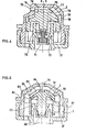
- the spraying device of FIG. 1, generally designated under the reference 1, essentially comprises a shutter 30, movable inside a diffuser body comprising a cover 2, closing the container 10.
- This cover has internally a cylindrical skirt 3, inside which are hollowed, in the axial direction, grooves 4 which, in the embodiment shown, are two in number and diametrically opposite. Outside the skirt 3, inside the container, the cover forms an annular projection 6 with surfaces having an inclination such that the coupling function which will be mentioned later can be fulfilled.
- An annular ring 5 connects the internal skirt 3 to an external skirt 7 by which the cover is fixed by screwing or snap-fastening on the neck of the container 10, shown only partially.
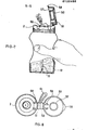
- the container 10 is, on the other hand, shown in FIG. 7, where it can be seen that it is made of a flexible plastic material which makes it deformable by hand by the user and ready to resume its initial shape after effort by elasticity.
- the compression of the container by the user causes the operation in the spraying phase while the return to the normal position sucks outside air into the container.
- the upper part 11 of the cover 2, closing the central part above the internal skirt 3, is constituted by a wall, the internal face of which forms at least one flat surface 13.
- the flat surface 13 is arranged obliquely to the axis of the cover 12 and is circular.
- An orifice 14 is drilled through the wall of the cover at the center of the flat part 13, in an orientation that is also oblique.
- the bearing surface 13 is provided with grooves forming channels 15, in radiating arrangement and opening tangentially into the orifice 14.
- the grooves are distributed regularly, three in number. This design responds to that of a so-called vortex nozzle.
- the cover 2 communicates with the dip tube 16, which opens near the bottom of the container 10.
- this communication between the dip tube 16 and the cover 2 takes place by means of a connecting element constituted by a cup 17, a tubular lower extension 18 of which is provided with annular grooves and beads 19 ensuring the tight junction with the dip tube.
- a connecting element constituted by a cup 17, a tubular lower extension 18 of which is provided with annular grooves and beads 19 ensuring the tight junction with the dip tube.
- any other connection method by snap-fastening or otherwise.
- the cup 17 forms an annular hollow surrounded by an external skirt 20 and by a central chimney 23, the latter being in the extension of the lower tubular part 18.
- the external skirt 20 has at its upper end an internal step 21 which ensures coupling practically sealed with the annular projection 6 of the skirt 3 of the cover 2.
- the bottom of the bowl 17 is pierced with one or more orifices 22, generally three in number, which allow the passage of air in one direction and in the other, between the volume of air surmounting the liquid in the container and the internal part of the diffuser delimited by the cup 17 and the central upper part of the cover 2.
- This internal part communicates, moreover, with the dip tube 16 from inside the chimney 23, at a valve seat formed by an internal lip 27 of this skirt.
- the shutter 30 cooperates with this valve seat to close the communication between the interior of the diffuser body and the dip tube when this shutter is in the position corresponding to the air suction phase after a spraying operation.
- the shutter 30 is movable inside the diffuser between two extreme positions, the low position corresponding to the air suction phase and the high position to the spraying phase.
- This shutter comprises an axial rod 40, surmounted by a cap 31.
- the axial rod 40 is hollow, in the particular case shown. It constitutes the closing element of the dip tube and has at the end a shape adapted to its function of precise tight contact on the lip 27, with a frustoconical section in the particular case shown.
- the cap 31 internally forms an annular hollow open towards the bottom, into which the chimney 23 of the cup 17 penetrates, but without contact between their respective walls. This arrangement makes it possible to effectively guide the liquid which leaves the dip tube when the shutter is pushed upwards for spraying. Indeed, the orifices 28, which will be discussed later, open inside an annular part 81 which extends the cap at the periphery, around the chimney 23 of the cup.
- the outer face of the shutter cap has a flat surface 33, of circular outline, which in the spraying position, bears on the flat surface 13 of the cover that has already been described. For an oblique transmission, these ranges are themselves oblique and off-center relative to the axis of the device. It has already been mentioned that grooves 15 are dug in the surface 13 in a radiating arrangement, but tangential with respect to the orifice 14, which makes it possible to ensure, in the phase of spraying, the operation of a vortex nozzle. In a comparable manner, the bearing surface 33 of the shutter is hollowed out with grooves 32. These grooves are three in number, of the same shape, and in correspondence with the grooves 15; this number is to be used most often, but it is in no way limiting. Outside the grooves, the parts 13 and 33 have corresponding shapes to come to bear perfectly.
- the grooves 32 open in a common recess 29 which is positioned opposite the spray orifice 14. At their radially opposite end, they open at the level of orifices 28 drilled through the wall of the shutter cap. It is understood that these orifices 28 allow the air to pass between the top and the bottom of the cap 31, but their role is above all to allow the passage of the liquid in the spraying phase.
- the respective grooves 15 and 32 cooperate to form channels which represent the only passage available for the liquid which is pushed through the orifices. 28 and leads through these channels to the outlet orifice 14. This is how the vortex nozzle is formed.
- the spray passage section is defined by these channels, and in no way by the section of the orifice 14.
- the liquid is on the other hand mixed with air which comes from inside the container by the orifices 22 and which provides a venturi effect.
- the air and liquid flow rates in the sprayed mixture are determined independently.
- the proportion of liquid is linked to the dimensions of the orifices 28 and to the opening of the valve of the dip tube.
- the amount of air is defined by the dimensions of orifices 22, it being understood qu'iej the obturator is sized to create no E restriction in its passage around the periphery.
- the air which mixes with the liquid at the entrance of the bus channels l causes the liquid to burst into droplets even before the mixture is expelled to the outside.
- the section of the outlet orifice is, in turn, freely determined to allow the best possible return of air when the container returns to its initial shape, by elasticity, after a spraying operation.
- the cap 31 of the shutter represents a large area sensitive to the effects of the expulsion pressure as the suction pressure.
- the particular form which has been described is not, however, limiting.
- the channels leading to the liquid / air mixture could be formed only either on the cap of the shutter, or on the internal face of the cover.
- the shutter 30 is fixed in rotation in its longitudinal movements relative to the cover 2.
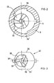
- the cap 31 comprises externally, on the annular part 81, two wings 37, in diametrically opposite positions, which slide in the longitudinal grooves 4 of the internal skirt of the cover.
- Figure 2 shows that in addition to these grooves 4, the skirt 3 of the cover forms large recesses 34 and 34 ', leaving a free space in these places between the shutter and the cover, while the section of the part ring 81 has flats 35 and 35 'which further increase the space.
- This design facilitates the passage of air flowing through the orifices 14 and 22, mainly bypassing the shutter, and incidentally through the orifices 28 in the suction phase.
- the shutter 30 is made in two parts: it comprises a valve 71, the lower part of which constitutes the closing element of the dip tube cooperating with the lip 27 of the shutter, and the upper part of which is contained in a cavity 72 of the rest of the shutter.
- the connection provided at this level allows a longitudinal sliding between two extreme stop positions, which are such that they do not interfere with the closure on the lip 27 on the one hand, the abutment of the cooperating faces forming the spray nozzle d 'somewhere else.
- the movements of the valve 71 relative to the rest of the shutter 30 improve the operation of the device thanks to a sudden drive of the shutter when it leaves the closed position of the dip tube.
- the design of the upper part of the shutter, forming in particular the cap, differs from FIG. 1 in that the hood, the shutter, and the nozzle which they form together are designed to ensure horizontal spraying; that is to say perpendicular to the axis of the device.
- the outlet orifice 73 is pierced through a vertical wall 74 of the cover, against which the shutter slides, by a vertical plane face.
- the flat surfaces of the cover and of the shutter which come into abutment in the spraying position are shown at 75 and 76 respectively.
- the channels of the nozzle are formed by grooves 77, formed in the shutter only. Only two grooves are provided. They compete opposite the orifice 73, and terminate, at their other ends, at the end of two channels 78 which join the space included under the cap of the shutter. Naturally, more grooves can be provided, but all on the side opposite the outlet orifice 73.
- the shape of the obturator cap contributes to effectively channeling the liquid towards the nozzle, while the air return circuit at the end of spraying is separated, since it is located mainly outside the shutter.
- the rear 79 and lateral faces are largely released from the cover, to facilitate this return of air when the faces 75 and 76 are no longer in support.
- FIG. 5 is also very similar to that of FIG. 1, but this time adapted to spray the liquid / air mixture, vertically in the axis of the container and of the spraying device.
- the cover 2 the cup 17 and the shutter 30, with its cap 31, extended downwards by a longitudinal annular part 81 carrying the guide wings 37.
- the nozzle has three channels formed against the underside 85 of the cover 2, which is smooth, by three grooves 82 hollowed out on the top of the cap 31, to conduct the liquid / air mixture admitted by peripheral orifices 83 up to the axial recess 84, with a swirling effect. Therefore, it has not been useful to provide guide grooves inside the skirt 3 of the cover, the wings 37 ensuring centering without any particular orientation.
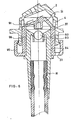
- the embodiment of Figure 6 differs from those which have been described so far in that the two functions of the shutter are devolved to two distinct organs.
- the embodiment of the spray nozzle part is strictly in accordance with that of FIG. 1, as well as that of the cap 31 of the shutter, with its guide wings 37 which slide in grooves 4 of the cover 2.
- the rod axial 91 integral with the cap 31 does not directly play the role of a closure element with respect to the communication with the dip tube 16. This role is provided by a ball 92 forming a valve.
- the ball 92 is movable between a lower position where, by the vacuum created after spraying, it is pressed against a valve seat constituted by a lip 93, present inside a sleeve 94 mounted on the upper end of the tube plunger, and an upper position where pushed by the liquid pressure, it is retained by the rod 91.
- the shutter of the device according to the invention always combines the function of opening and closing the arrival of liquid with the function which alternately consists of forming the spray nozzle and releasing the air inlet.
- the spraying device according to the invention is protected by a cap 50 forming a tamper-evident capsule.
- This cap closes on the cap 2, which it completely covers, by being folded down around a hinge pin formed by two pivots 56 carried by projections provided under the cap 50, which pivots are housed in cavities 60 provided in corresponding projections provided on the top of the cover 2.
- the cap 50 In a position diametrically opposite the axis of articulation, the cap 50 has a tongue 58 which is used to lift it with the finger. It also includes a cylindrical skirt 57, the lower edge of which snaps onto a bead 59 with which the central part of the cover 2 is provided. Sealing in the closed position is thus ensured.
- cover 2 and the cap 50 are initially connected by their edges, on the side of the articulation axis, by strands 51, easily fracturable, to the four corners of a flexible plate 53, which is thus folded in two in the middle until the first use.
- the low resistance of the strands 51 makes it possible to separate the plate 53 when the user lifts the cap 50 for the first time, forcing slightly around the joint.
- the plate 53 can also be eliminated beforehand by pulling on an eyelet 61 specially provided for this purpose.
Landscapes
- Containers And Packaging Bodies Having A Special Means To Remove Contents (AREA)
- Nozzles (AREA)
- Closures For Containers (AREA)
- Fuel-Injection Apparatus (AREA)
- Catching Or Destruction (AREA)
- User Interface Of Digital Computer (AREA)
- Coating Apparatus (AREA)
Priority Applications (1)
| Application Number | Priority Date | Filing Date | Title |
|---|---|---|---|
| AT84401172T ATE36816T1 (de) | 1983-06-14 | 1984-06-06 | Spritzkopf fuer einen verformbaren behaelter. |
Applications Claiming Priority (2)
| Application Number | Priority Date | Filing Date | Title |
|---|---|---|---|
| ES1983272902U ES272902Y (es) | 1983-06-14 | 1983-06-14 | "pulverizador para recipientes deformables manualmente" |
| ES272902 | 1983-06-14 |
Publications (3)
| Publication Number | Publication Date |
|---|---|
| EP0129465A2 true EP0129465A2 (de) | 1984-12-27 |
| EP0129465A3 EP0129465A3 (en) | 1985-12-18 |
| EP0129465B1 EP0129465B1 (de) | 1988-08-31 |
Family
ID=8426066
Family Applications (1)
| Application Number | Title | Priority Date | Filing Date |
|---|---|---|---|
| EP84401172A Expired EP0129465B1 (de) | 1983-06-14 | 1984-06-06 | Spritzkopf für einen verformbaren Behälter |
Country Status (17)
| Country | Link |
|---|---|
| US (1) | US4673110A (de) |
| EP (1) | EP0129465B1 (de) |
| JP (1) | JPH0661513B2 (de) |
| AT (1) | ATE36816T1 (de) |
| AU (1) | AU575835B2 (de) |
| BR (1) | BR8402879A (de) |
| CA (1) | CA1276604C (de) |
| DE (2) | DE3473734D1 (de) |
| DK (1) | DK162485C (de) |
| ES (1) | ES272902Y (de) |
| FI (1) | FI75745C (de) |
| GR (1) | GR82213B (de) |
| IN (1) | IN161984B (de) |
| NO (1) | NO163123C (de) |
| PT (1) | PT78721B (de) |
| ZA (1) | ZA844487B (de) |
| ZW (1) | ZW8684A1 (de) |
Cited By (1)
| Publication number | Priority date | Publication date | Assignee | Title |
|---|---|---|---|---|
| EP0682987A3 (de) * | 1994-05-19 | 1996-08-21 | Pfeiffer Erich Gmbh & Co Kg | Austragvorrichtung für Medien. |
Families Citing this family (24)
| Publication number | Priority date | Publication date | Assignee | Title |
|---|---|---|---|---|
| US4773570A (en) * | 1983-06-14 | 1988-09-27 | Interscents N.V. | Discharge device for a deformable container |
| US4836422A (en) * | 1987-02-11 | 1989-06-06 | Henkel Kommanditgesellschaft Auf Aktien | Propellantless foam dispenser |
| DE3710788A1 (de) * | 1987-03-31 | 1988-11-10 | Wolfgang Fuhrig | Handdruckzerstaeuber |
| DE3712894A1 (de) * | 1987-04-16 | 1988-11-03 | Hans Heinlein | Sprueheinsatz fuer elastisch deformierbare fluessigkeitsbehaelter |
| US4813577A (en) * | 1988-03-04 | 1989-03-21 | Carow International, Inc. | Multiple flow dispensing cap |
| FR2665848B1 (fr) * | 1990-08-17 | 1992-10-30 | Aerosols & Bouchage | Buses a clapet incorpore. |
| NL9100746A (nl) * | 1991-05-01 | 1992-12-01 | Interscents Nv | Verstuivingsinrichting voor deformeerbare houder. |
| US5409136A (en) * | 1991-05-01 | 1995-04-25 | Interscents N.V. | Spraying device for deformable container able to divert vertical spray into spray at an angle |
| FR2711930B1 (fr) * | 1993-11-03 | 1996-01-26 | Sofab | Dispositif de pulvérisation. |
| US5904272A (en) * | 1997-11-12 | 1999-05-18 | Kaufman Products Inc. | Dispenser for liquids |
| US6382204B1 (en) | 1999-10-14 | 2002-05-07 | Becton Dickinson And Company | Drug delivery system including holder and drug container |
| USD446578S1 (en) | 1999-10-14 | 2001-08-14 | Becton, Dickinson And Company | Drug container holder |
| USD447559S1 (en) | 1999-10-14 | 2001-09-04 | Becton, Dickinson And Company | Drug container holder |
| USD463546S1 (en) | 1999-10-14 | 2002-09-24 | Becton Dickinson And Company | Drug container holder |
| USD448474S1 (en) | 1999-10-14 | 2001-09-25 | Becton, Dickinson And Company | Drug container holder |
| US6250568B1 (en) | 2000-03-22 | 2001-06-26 | Saint-Gobain Calmar Inc. | Squeeze bottle aspirator |
| US6868990B2 (en) * | 2002-09-26 | 2005-03-22 | Emsar, Inc. | Fluid dispenser with shuttling mixing chamber |
| FR2858567B1 (fr) * | 2003-08-04 | 2006-03-03 | Valois Sas | Tete de pulverisation de produit fluide |
| EP1602298B1 (de) * | 2004-06-04 | 2012-10-03 | Schwan-STABILO Cosmetics GmbH & Co. KG | Auftraggerät |
| NL1030993C2 (nl) * | 2006-01-24 | 2007-07-26 | Airspray Nv | Knijpschuimvormer. |
| US8662419B2 (en) * | 2010-01-28 | 2014-03-04 | Chang Ho Chang | Multifunctional spraying mineral water bottle |
| CN101973430B (zh) * | 2010-10-22 | 2014-08-13 | (文莱)希米亚股份有限公司东莞代表处 | 一种运动型多功能喷雾矿泉水瓶 |
| GB2479014B (en) * | 2010-03-26 | 2016-05-11 | Shenzhen Nozo Ip Operation Co Ltd | A multifunctional spraying mineral water bottle |
| FR3141148B1 (fr) * | 2022-10-24 | 2024-12-13 | Oreal | Pulverisateur avec chambre de precompression |
Family Cites Families (16)
| Publication number | Priority date | Publication date | Assignee | Title |
|---|---|---|---|---|
| US2353355A (en) * | 1942-03-13 | 1944-07-11 | Okies Joe | Dispensing container |
| BE554133A (de) * | 1956-01-12 | |||
| FR1485415A (fr) * | 1965-07-06 | 1967-06-16 | Ncr Co | Système de reconnaissance optique des caractères |
| SE316128B (de) * | 1965-07-23 | 1969-10-13 | Ind Cervello Sa | |
| FR1485417A (fr) * | 1966-07-05 | 1967-06-16 | Cervello Ind | Bouchon pulvérisateur avec soupape d'admission d'air applicable à des flacons flexibles |
| FR1485416A (fr) * | 1966-07-05 | 1967-06-16 | Cervello Ind | Tubulure-soupape destinée à faciliter l'admission d'air, applicable à des bouchons pulvérisateurs pour flacons flexibles |
| US3493179A (en) * | 1968-01-12 | 1970-02-03 | Tsu Hsuen Lee | Squeeze bottle |
| US3604596A (en) * | 1969-01-17 | 1971-09-14 | Continental Can Co | Tamper-indicating closures |
| US3963150A (en) * | 1974-05-21 | 1976-06-15 | Vca Corporation | Puff-discharge squeeze bottle |
| DE2548396A1 (de) * | 1974-11-28 | 1976-08-12 | Rosalba Senegaglia | Betaetigungsknopf mit automatischer unterbrechung des ausflusses von unter druck stehenden fluessigen stoffen |
| US4020979A (en) * | 1975-10-15 | 1977-05-03 | Summit Packaging Systems, Inc. | Squeeze-bottle-type spray dispenser |
| FR2341369A1 (fr) * | 1976-02-19 | 1977-09-16 | Aerosol Inventions Dev | Recipient pulverisateur |
| FR2364168A1 (fr) * | 1976-09-10 | 1978-04-07 | Workum Donald | Dispositif de pulverisation |
| JPS6027481Y2 (ja) * | 1980-03-05 | 1985-08-19 | 株式会社吉野工業所 | トリガ−式液体噴出器のノズル |
| SE455190B (sv) * | 1981-04-27 | 1988-06-27 | Axel Crone | Huvenhet |
| DE3137760A1 (de) * | 1981-09-23 | 1983-07-14 | Bayer Ag, 5090 Leverkusen | Vorrichtung zum dosieren von pastoesen stoffen |
-
1983
- 1983-06-14 ES ES1983272902U patent/ES272902Y/es not_active Expired
-
1984
- 1984-05-22 GR GR74786A patent/GR82213B/el unknown
- 1984-05-25 FI FI842121A patent/FI75745C/fi not_active IP Right Cessation
- 1984-05-31 AU AU28881/84A patent/AU575835B2/en not_active Ceased
- 1984-06-04 US US06/616,942 patent/US4673110A/en not_active Expired - Lifetime
- 1984-06-06 EP EP84401172A patent/EP0129465B1/de not_active Expired
- 1984-06-06 DE DE8484401172T patent/DE3473734D1/de not_active Expired
- 1984-06-06 AT AT84401172T patent/ATE36816T1/de not_active IP Right Cessation
- 1984-06-09 DE DE19848417652U patent/DE8417652U1/de not_active Expired
- 1984-06-12 JP JP59121649A patent/JPH0661513B2/ja not_active Expired - Lifetime
- 1984-06-12 PT PT78721A patent/PT78721B/pt not_active IP Right Cessation
- 1984-06-13 IN IN404/CAL/84A patent/IN161984B/en unknown
- 1984-06-13 DK DK289784A patent/DK162485C/da active
- 1984-06-13 NO NO84842365A patent/NO163123C/no not_active IP Right Cessation
- 1984-06-13 BR BR8402879A patent/BR8402879A/pt not_active IP Right Cessation
- 1984-06-14 CA CA000456604A patent/CA1276604C/en not_active Expired - Lifetime
- 1984-06-14 ZW ZW86/84A patent/ZW8684A1/xx unknown
- 1984-06-14 ZA ZA844487A patent/ZA844487B/xx unknown
Cited By (2)
| Publication number | Priority date | Publication date | Assignee | Title |
|---|---|---|---|---|
| EP0682987A3 (de) * | 1994-05-19 | 1996-08-21 | Pfeiffer Erich Gmbh & Co Kg | Austragvorrichtung für Medien. |
| AU691884B2 (en) * | 1994-05-19 | 1998-05-28 | Ing. Erich Pfeiffer Gmbh & Co. Kg | Discharge apparatus for media |
Also Published As
| Publication number | Publication date |
|---|---|
| ZW8684A1 (en) | 1984-11-07 |
| ATE36816T1 (de) | 1988-09-15 |
| EP0129465B1 (de) | 1988-08-31 |
| NO163123B (no) | 1990-01-02 |
| JPS6064660A (ja) | 1985-04-13 |
| DK289784D0 (da) | 1984-06-13 |
| NO163123C (no) | 1990-04-11 |
| ES272902U (es) | 1983-11-01 |
| EP0129465A3 (en) | 1985-12-18 |
| ZA844487B (en) | 1985-01-30 |
| JPH0661513B2 (ja) | 1994-08-17 |
| DK289784A (da) | 1984-12-15 |
| DK162485C (da) | 1992-03-30 |
| FI75745C (fi) | 1988-08-08 |
| FI842121A0 (fi) | 1984-05-25 |
| DE8417652U1 (de) | 1984-10-18 |
| DK162485B (da) | 1991-11-04 |
| PT78721B (fr) | 1986-07-11 |
| DE3473734D1 (en) | 1988-10-06 |
| AU2888184A (en) | 1984-12-20 |
| BR8402879A (pt) | 1985-05-21 |
| US4673110A (en) | 1987-06-16 |
| ES272902Y (es) | 1984-05-01 |
| PT78721A (pt) | 1985-01-01 |
| NO842365L (no) | 1984-12-17 |
| IN161984B (de) | 1988-03-12 |
| FI842121A7 (fi) | 1984-12-15 |
| CA1276604C (en) | 1990-11-20 |
| GR82213B (de) | 1984-12-13 |
| FI75745B (fi) | 1988-04-29 |
| AU575835B2 (en) | 1988-08-11 |
Similar Documents
| Publication | Publication Date | Title |
|---|---|---|
| EP0129465B1 (de) | Spritzkopf für einen verformbaren Behälter | |
| EP1048590B1 (de) | Ventilbetätigungsvorrichtung und Einrichtung mit einer solchen Vorrichtung | |
| CA2305005A1 (fr) | Dispositif pour le melange extemporane d'au moins deux produits dont un est notamment une poudre | |
| EP0826606A1 (de) | Spenderkappe mit verbesserter Greifmöglichkeit | |
| EP0888823A1 (de) | Pumpanordnung enthaltender Spender für pastöses oder flüssiges Material | |
| FR2752820A1 (fr) | Capsule de distribution a etancheite amelioree | |
| EP0437131B1 (de) | Vordruck-Handpumpe zum zerstäuben einer Flüssigkeit, insbesondere eines Parfüms | |
| EP1472007B1 (de) | Spender für fliessfähige medien mit einer pumpe | |
| EP1002735B1 (de) | Pumpe und damit ausgerüsteter Behälter | |
| FR2954754A1 (fr) | Capsule distributrice pour flacon de produit de consistance liquide ou visqueuse et flacon muni d'une telle capsule | |
| EP0960829B1 (de) | Ventil sowie Aufbewahrungs- und Ausgabevorrichtung mit einem solchen Ventil | |
| EP2331267B1 (de) | Vorrichtung zum verteilen von flüssigkeiten | |
| EP0544549B1 (de) | Pumpe zur Förderung von einem flüssigen oder pastösen Produkt, und Ausgabebehälter mit einer solchen Pumpe | |
| EP1412093A1 (de) | Einen dosierstab bildender spender für flüssige oder gelartige produkte | |
| EP0605275B1 (de) | Anordnung zur Zerstäubung einer Flüssigkeit mit einer Vordruckpumpe | |
| FR2713608A1 (fr) | Valve pour la distribution sous forme pulvérisée d'un liquide, et récipient pressurisé équipé d'une telle valve. | |
| EP0373989B1 (de) | Behälterverschlusskappe mit schwenkbarem Betätigungselement zum Abgeben des Behälterinhalts | |
| FR2671330A1 (fr) | Distributeur manuel portatif a pompe pour creme et cosmetique. | |
| EP0331561A1 (de) | Vorrichtung, die die Verwendung eines Sprühventils in jeder Stellung erlaubt | |
| FR2708314A1 (fr) | Perfectionnements aux pompes doseuses. | |
| FR2853697A1 (fr) | Pompe et recipient ainsi equipe | |
| EP0832579B1 (de) | Verbesserte Drehhülse, wie Lippenstifthülse | |
| EP0499537B1 (de) | Vorrichtung zur Zerstäubung oder Abgabe eines flüssigen Produktes mit einem Schiebesteigrohr im Saugrohr | |
| FR2647418A1 (fr) | Distributeur doseur de produit liquide ou pateux | |
| FR2912670A1 (fr) | Dispositif de distribution de produit fluide |
Legal Events
| Date | Code | Title | Description |
|---|---|---|---|
| PUAI | Public reference made under article 153(3) epc to a published international application that has entered the european phase |
Free format text: ORIGINAL CODE: 0009012 |
|
| AK | Designated contracting states |
Designated state(s): AT BE CH DE FR GB IT LI LU NL SE |
|
| 17P | Request for examination filed |
Effective date: 19850622 |
|
| PUAL | Search report despatched |
Free format text: ORIGINAL CODE: 0009013 |
|
| AK | Designated contracting states |
Designated state(s): AT BE CH DE FR GB IT LI LU NL SE |
|
| 17Q | First examination report despatched |
Effective date: 19870427 |
|
| RAP1 | Party data changed (applicant data changed or rights of an application transferred) |
Owner name: INTERSCENTS N.V. |
|
| GRAA | (expected) grant |
Free format text: ORIGINAL CODE: 0009210 |
|
| AK | Designated contracting states |
Kind code of ref document: B1 Designated state(s): AT BE CH DE FR GB IT LI LU NL SE |
|
| REF | Corresponds to: |
Ref document number: 36816 Country of ref document: AT Date of ref document: 19880915 Kind code of ref document: T |
|
| REF | Corresponds to: |
Ref document number: 3473734 Country of ref document: DE Date of ref document: 19881006 |
|
| ITF | It: translation for a ep patent filed | ||
| GBT | Gb: translation of ep patent filed (gb section 77(6)(a)/1977) | ||
| PLBE | No opposition filed within time limit |
Free format text: ORIGINAL CODE: 0009261 |
|
| STAA | Information on the status of an ep patent application or granted ep patent |
Free format text: STATUS: NO OPPOSITION FILED WITHIN TIME LIMIT |
|
| 26N | No opposition filed | ||
| ITTA | It: last paid annual fee | ||
| EPTA | Lu: last paid annual fee | ||
| EAL | Se: european patent in force in sweden |
Ref document number: 84401172.6 |
|
| PGFP | Annual fee paid to national office [announced via postgrant information from national office to epo] |
Ref country code: FR Payment date: 20000522 Year of fee payment: 17 |
|
| PGFP | Annual fee paid to national office [announced via postgrant information from national office to epo] |
Ref country code: LU Payment date: 20000530 Year of fee payment: 17 |
|
| PGFP | Annual fee paid to national office [announced via postgrant information from national office to epo] |
Ref country code: GB Payment date: 20000602 Year of fee payment: 17 |
|
| PGFP | Annual fee paid to national office [announced via postgrant information from national office to epo] |
Ref country code: AT Payment date: 20000615 Year of fee payment: 17 |
|
| PGFP | Annual fee paid to national office [announced via postgrant information from national office to epo] |
Ref country code: SE Payment date: 20000616 Year of fee payment: 17 |
|
| PGFP | Annual fee paid to national office [announced via postgrant information from national office to epo] |
Ref country code: BE Payment date: 20000711 Year of fee payment: 17 |
|
| PGFP | Annual fee paid to national office [announced via postgrant information from national office to epo] |
Ref country code: DE Payment date: 20000830 Year of fee payment: 17 |
|
| PGFP | Annual fee paid to national office [announced via postgrant information from national office to epo] |
Ref country code: CH Payment date: 20000906 Year of fee payment: 17 |
|
| PGFP | Annual fee paid to national office [announced via postgrant information from national office to epo] |
Ref country code: NL Payment date: 20001030 Year of fee payment: 17 |
|
| PG25 | Lapsed in a contracting state [announced via postgrant information from national office to epo] |
Ref country code: LU Free format text: LAPSE BECAUSE OF NON-PAYMENT OF DUE FEES Effective date: 20010606 Ref country code: GB Free format text: LAPSE BECAUSE OF NON-PAYMENT OF DUE FEES Effective date: 20010606 Ref country code: AT Free format text: LAPSE BECAUSE OF NON-PAYMENT OF DUE FEES Effective date: 20010606 |
|
| PG25 | Lapsed in a contracting state [announced via postgrant information from national office to epo] |
Ref country code: SE Free format text: LAPSE BECAUSE OF NON-PAYMENT OF DUE FEES Effective date: 20010607 |
|
| PG25 | Lapsed in a contracting state [announced via postgrant information from national office to epo] |
Ref country code: LI Free format text: LAPSE BECAUSE OF NON-PAYMENT OF DUE FEES Effective date: 20010630 Ref country code: CH Free format text: LAPSE BECAUSE OF NON-PAYMENT OF DUE FEES Effective date: 20010630 Ref country code: BE Free format text: LAPSE BECAUSE OF NON-PAYMENT OF DUE FEES Effective date: 20010630 |
|
| BERE | Be: lapsed |
Owner name: INTERSCENTS N.V. Effective date: 20010630 |
|
| PG25 | Lapsed in a contracting state [announced via postgrant information from national office to epo] |
Ref country code: NL Free format text: LAPSE BECAUSE OF NON-PAYMENT OF DUE FEES Effective date: 20020101 |
|
| GBPC | Gb: european patent ceased through non-payment of renewal fee |
Effective date: 20010606 |
|
| EUG | Se: european patent has lapsed |
Ref document number: 84401172.6 |
|
| REG | Reference to a national code |
Ref country code: CH Ref legal event code: PL |
|
| PG25 | Lapsed in a contracting state [announced via postgrant information from national office to epo] |
Ref country code: FR Free format text: LAPSE BECAUSE OF NON-PAYMENT OF DUE FEES Effective date: 20020228 |
|
| NLV4 | Nl: lapsed or anulled due to non-payment of the annual fee |
Effective date: 20020101 |
|
| PG25 | Lapsed in a contracting state [announced via postgrant information from national office to epo] |
Ref country code: DE Free format text: LAPSE BECAUSE OF NON-PAYMENT OF DUE FEES Effective date: 20020403 |