EP0129516B1 - Machine pour l'étirage de nappes de fibres textiles - Google Patents
Machine pour l'étirage de nappes de fibres textiles Download PDFInfo
- Publication number
- EP0129516B1 EP0129516B1 EP84830153A EP84830153A EP0129516B1 EP 0129516 B1 EP0129516 B1 EP 0129516B1 EP 84830153 A EP84830153 A EP 84830153A EP 84830153 A EP84830153 A EP 84830153A EP 0129516 B1 EP0129516 B1 EP 0129516B1
- Authority
- EP
- European Patent Office
- Prior art keywords
- rolls
- drawing apparatus
- pair
- coverings
- web
- Prior art date
- Legal status (The legal status is an assumption and is not a legal conclusion. Google has not performed a legal analysis and makes no representation as to the accuracy of the status listed.)
- Expired
Links
- 239000004753 textile Substances 0.000 title claims description 5
- 239000000835 fiber Substances 0.000 title claims description 3
- 230000002093 peripheral effect Effects 0.000 claims description 11
- 229910000831 Steel Inorganic materials 0.000 claims description 4
- 239000010959 steel Substances 0.000 claims description 4
- 238000009960 carding Methods 0.000 description 3
- 230000015572 biosynthetic process Effects 0.000 description 2
- 230000000694 effects Effects 0.000 description 2
- 238000010924 continuous production Methods 0.000 description 1
- 239000002184 metal Substances 0.000 description 1
- 229920002994 synthetic fiber Polymers 0.000 description 1
- 239000004758 synthetic textile Substances 0.000 description 1
Images

Classifications
-
- D—TEXTILES; PAPER
- D04—BRAIDING; LACE-MAKING; KNITTING; TRIMMINGS; NON-WOVEN FABRICS
- D04H—MAKING TEXTILE FABRICS, e.g. FROM FIBRES OR FILAMENTARY MATERIAL; FABRICS MADE BY SUCH PROCESSES OR APPARATUS, e.g. FELTS, NON-WOVEN FABRICS; COTTON-WOOL; WADDING ; NON-WOVEN FABRICS FROM STAPLE FIBRES, FILAMENTS OR YARNS, BONDED WITH AT LEAST ONE WEB-LIKE MATERIAL DURING THEIR CONSOLIDATION
- D04H1/00—Non-woven fabrics formed wholly or mainly of staple fibres or like relatively short fibres
- D04H1/70—Non-woven fabrics formed wholly or mainly of staple fibres or like relatively short fibres characterised by the method of forming fleeces or layers, e.g. reorientation of fibres
- D04H1/74—Non-woven fabrics formed wholly or mainly of staple fibres or like relatively short fibres characterised by the method of forming fleeces or layers, e.g. reorientation of fibres the fibres being orientated, e.g. in parallel (anisotropic fleeces)
-
- D—TEXTILES; PAPER
- D01—NATURAL OR MAN-MADE THREADS OR FIBRES; SPINNING
- D01H—SPINNING OR TWISTING
- D01H5/00—Drafting machines or arrangements ; Threading of roving into drafting machine
- D01H5/18—Drafting machines or arrangements without fallers or like pinned bars
- D01H5/22—Drafting machines or arrangements without fallers or like pinned bars in which fibres are controlled by rollers only
- D01H5/24—Drafting machines or arrangements without fallers or like pinned bars in which fibres are controlled by rollers only with porcupines or like pinned rotary members
-
- D—TEXTILES; PAPER
- D04—BRAIDING; LACE-MAKING; KNITTING; TRIMMINGS; NON-WOVEN FABRICS
- D04H—MAKING TEXTILE FABRICS, e.g. FROM FIBRES OR FILAMENTARY MATERIAL; FABRICS MADE BY SUCH PROCESSES OR APPARATUS, e.g. FELTS, NON-WOVEN FABRICS; COTTON-WOOL; WADDING ; NON-WOVEN FABRICS FROM STAPLE FIBRES, FILAMENTS OR YARNS, BONDED WITH AT LEAST ONE WEB-LIKE MATERIAL DURING THEIR CONSOLIDATION
- D04H1/00—Non-woven fabrics formed wholly or mainly of staple fibres or like relatively short fibres
- D04H1/70—Non-woven fabrics formed wholly or mainly of staple fibres or like relatively short fibres characterised by the method of forming fleeces or layers, e.g. reorientation of fibres
Definitions
- the present invention relates to drawing apparatus for webs of natural or synthetic textile fibres. More particularly, the invention relates to drawing apparatus used in the continuous production of non-woven textiles by drawing of several layers obtained by successive carding and cross-lapping operations.
- the drawing apparatus of the invention is of the type comprising :
- a drawing apparatus of this type is known from DE-A-2 259 919 ; however in said apparatus the rolls of each pair are smooth. Therefore it is not possible to achieve a uniform drawing ; one result of this is the possible formation of holes in the drawn web, particularly when the drawing ratio is high and the number of pairs of rolls is small.
- the object of the present invention is to provide a drawing apparatus of the type specified above which allows high drawing ratios to be achieved with a small number of pairs of rolls, without prejudicing the quality of the-web and particularly without giving raise to holes in the drawn web.
- the present invention provides a drawing apparatus of the type specified above in which the rolls of each pair are provided with resilient coverings constituted by highly flexible steel wires which extend substantially radially and each said smooth roller has a peripheral velocity equal to that of the following roll pair.
- the drawing apparatus illustrated in Figure 1 includes an inlet group A, an intermediate drawing group B, an outlet drawing group C, and an outlet group D.
- Reference numeral 1 indicates a conveyor belt which feeds a thick web M continuously to the drawing apparatus, the web M being obtained in known manner by successive carding of textile fibres and lapping of the web leaving the carding machine.
- a continuous belt 2 compresses the web M against the conveyor 1 which feeds the web to the inlet group A.
- the inlet group A is constituted by a pair of rolls 3, 4 each having a resilient covering, respectively 3a and 4a, constituted by highly flexible steel wires which extend substantially radially.
- the rolls 3, 4 have a peripheral velocity slightly greater than the velocity of the belts 1 and 2.
- the minimum distance between the resilient coverings 3a, 4a of the rolls 3, 4 measured in the zone S, that is, in the plane in which the axes of the two rolls lie, is of the order of several millimeters, for example 2-3 millimeters.
- the intermediate drawing group B includes a pair of drawing rolls 5, 6 each covered with a resilient covering, respectively 5a, 6a, and working in conjunction with a smooth roller 7 of smaller diameter which is interposed between the pairs of rolls 3, 4 and 5, 6 and cooperates with the upper rolls 3 and 5.
- the minimum distance between the resilient coverings 5a, 6a of the rolls 5, 6 measured in the zone T is equal to the minimum distance between the coverings of the rolls 3 and 4, while the minimum distance between the covering 5a and the roller 7 measured in the zone U is slightly greater and is, for example, 5-10 mm.
- the minimum distance between the covering 3a, and the roller 7 is still greater and is, for example, 10-15 mm.
- the rolls 5, 6 and roller 7 all have the same peripheral velocity which is greater than that of the rolls 3 and 4.
- the intermediate drawing group B may include two or more pairs of drawing rolls instead of a single pair as illustrated.
- the number of pairs of drawing rolls may vary in dependence on the maximum drawing ratio which it is desired to achieve, given that in order to achieve high drawing ratios together with a good quality of the web, it is -essential to effect drawing in small increments.
- the outlet drawing group C is constituted by a pair of rolls 8, 9, both having resilient coverings, respectively 8a, 9a and working in conjunction with a smooth roller 10 of smaller diameter interposed between the pairs of rolls 5, 6 and 8, 9 and cooperating with the lower rolls 6 and 9.
- the minimum distance between the resilient coverings of the rolls 8, 9 measured in the zone Z is equal to the minimum distance between the coverings of the pairs of rolls 3, 4 and 5, 6.
- the minimum spacing between the covering 6a and the roller 10 measured in the zone V is equal to the distance between the covering 3a the roller 7 while the minimum distance between the covering 9a and the roller 10 is equal to the minimum distance between the covering 5a and of the roller 7 in the zone U.
- the rolls 8, 9 and roller 10 all have the same peripheral velocity which is greater than that of the rolls 5, 6 and roller 7.
- the outlet group D is constituted by rollers 11, 12.
- the roller 11 which is smooth and of smaller diameter, is adjacent the pair of rolls 8, 9 and cooperates with the roll 9.
- the roller 12 has transverse rifling or a rigid cover.
- the rollers 11 and 12 have the same peripheral velocity as that of the rolls 8, 9 and roller 10.
- the minimum distance between the covering 9a and the roller 11 is equal to the minimum distance between this covering and the roller 10.
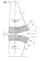
- FIG 2 illustrates, in greater detail, the resilient coverings 5a, 6a provided on the rolls 5, 6 and as stated previously, these coverings are identical to the coverings of the pairs of rolls 3, 4 and 8, 9.
- Each of these coverings is made up of a plurality of points each constituted by a circular cross-section metal wire 13 of a diameter of about 0.3 mm.
- the wires 13 are fixed to four rubber backing webs and have a free length of the order of 23.5 mm.
- the density of the wires is between 20 and 26 wires per square centimeter and is preferably 22 wires per square centimeter.
- the wires 13 extend substantially radially and have a small negative inclination, that is, an inclination in the opposite sense to the sense of rotation of the associated roll.
- the inclination X of the wires 13 could be between 0° and 10° negative.
- the said resilient coverings are of fundamental importance for achieving the objects of the invention.
- each individual wire 13 is able to withstand the pull of the fibres which constitue the web only for very low traction values after which the wire bends freeing the web and thus avoiding the formation of holes in the web itself.
- the smaller diameter rollers 7, 10 modify the path of the web between the zones S-T and T-Z to make it sinuous and cause pinching of the web at the points U and V.
- roller 7 keeps the web in contact with the covering of the rolls 3, 5 and the roller 10 keeps the web in contact with the coverings of the rolls 6, 9.
- the roller 7 may be moved closer to, or away from, the roll 5 and the roller 10 may be moved closer to, or away from, the roll 9 in dependence on the thickness of the web M.
- rollers 7 and 10 allow the web to be kept in engagement with the points of the covered roll pairs 3, 4 ; 6 and 8, 9 over substantial arcs which enables very effective control of the web during drawing to be achieved.
Landscapes
- Engineering & Computer Science (AREA)
- Textile Engineering (AREA)
- Mechanical Engineering (AREA)
- Preliminary Treatment Of Fibers (AREA)
- Treatment Of Fiber Materials (AREA)
Claims (9)
Priority Applications (1)
| Application Number | Priority Date | Filing Date | Title |
|---|---|---|---|
| AT84830153T ATE26135T1 (de) | 1983-05-24 | 1984-05-21 | Streckmaschine fuer textile faservliese. |
Applications Claiming Priority (4)
| Application Number | Priority Date | Filing Date | Title |
|---|---|---|---|
| IT67575/83A IT1203674B (it) | 1983-05-24 | 1983-05-24 | Stiratoio per veli faldati di fibre tessili |
| IT6757583 | 1983-05-24 | ||
| IT6706484 | 1984-01-23 | ||
| IT67064/84A IT1178837B (it) | 1984-01-23 | 1984-01-23 | Stiratoio per veli faldati di fibre tessili |
Publications (2)
| Publication Number | Publication Date |
|---|---|
| EP0129516A1 EP0129516A1 (fr) | 1984-12-27 |
| EP0129516B1 true EP0129516B1 (fr) | 1987-03-25 |
Family
ID=26329699
Family Applications (1)
| Application Number | Title | Priority Date | Filing Date |
|---|---|---|---|
| EP84830153A Expired EP0129516B1 (fr) | 1983-05-24 | 1984-05-21 | Machine pour l'étirage de nappes de fibres textiles |
Country Status (4)
| Country | Link |
|---|---|
| US (1) | US4547936A (fr) |
| EP (1) | EP0129516B1 (fr) |
| DE (2) | DE129516T1 (fr) |
| ES (1) | ES279414Y (fr) |
Families Citing this family (8)
| Publication number | Priority date | Publication date | Assignee | Title |
|---|---|---|---|---|
| US4794680A (en) * | 1985-12-20 | 1989-01-03 | Union Carbide Corporation | Novel wear-resistant laser-engraved ceramic or metallic carbide surfaces for friction rolls for working elongate members, method for producing same and method for working elongate members using the novel friction roll |
| US4845813A (en) * | 1987-12-15 | 1989-07-11 | United States Of America, As Represented By The Secretary Of Agriculture | Roller drafter, process of use, and products produced thereby |
| FR2678288B1 (fr) * | 1991-06-28 | 1994-11-18 | Asselin Ets | Procede pour realiser un produit non-tisse semi-fini et produit non-tisse semi-fini. |
| FR2678289B1 (fr) * | 1991-06-28 | 1994-01-14 | Asselin Ets | Procede pour realiser un non-tisse, non-tisse obtenu notamment par ce procede et installation pour la fabrication de ce non-tisse. |
| IT1296086B1 (it) * | 1997-11-07 | 1999-06-09 | Marzoli & C Spa | Dispositivo per il controllo delle fibre flottanti tra i cilindri del gruppo di stiro appartenente ad una macchina pettinatrice. |
| ES2265058T3 (es) * | 2001-04-23 | 2007-02-01 | Autefa Automation Gmbh | Procedimiento para el perfilado de un material no tejido y dispositivo de formacion del perfil. |
| DE10139833A1 (de) * | 2001-08-14 | 2003-02-27 | Dilo Kg Maschf Oskar | Verfahren und Vorrichtung zum Herstellen eines Faservlieses |
| US7416638B2 (en) * | 2003-11-18 | 2008-08-26 | Georgia-Pacific Consumer Products Lp | Apparatus and method for manufacturing a multi-layer web product |
Family Cites Families (8)
| Publication number | Priority date | Publication date | Assignee | Title |
|---|---|---|---|---|
| US2023032A (en) * | 1933-10-24 | 1935-12-03 | Rooney Thomas Peter | Textile drafting device |
| FR1160567A (fr) * | 1956-11-19 | 1958-07-18 | Perfectionnements au train d'étirage des bobinoirs à peigne hérisson | |
| DE1560804A1 (fr) * | 1966-05-21 | 1972-03-16 | ||
| US3409946A (en) * | 1966-07-05 | 1968-11-12 | Ideal Ind | Apparatus for drafting textile fibrous strands |
| GB1332856A (en) * | 1970-05-14 | 1973-10-10 | Chubu Seiko Kk | Rotary drafting apparatus |
| GB1412732A (en) | 1971-08-13 | 1975-11-05 | Prtways Ltd | Method of manufacturing a non-woven fibrous web |
| DE2259919B2 (de) * | 1972-12-07 | 1975-04-17 | Fried. Krupp Gmbh, 4300 Essen | Vorrichtung zum Verziehen von wirr-, kreuz- oder längsgerichteten Faservliesen |
| FR2221547B1 (fr) * | 1973-03-13 | 1979-09-28 | Alsacienne Constr Meca |
-
1984
- 1984-05-21 DE DE198484830153T patent/DE129516T1/de active Pending
- 1984-05-21 DE DE8484830153T patent/DE3462805D1/de not_active Expired
- 1984-05-21 EP EP84830153A patent/EP0129516B1/fr not_active Expired
- 1984-05-23 ES ES1984279414U patent/ES279414Y/es not_active Expired
- 1984-05-24 US US06/613,487 patent/US4547936A/en not_active Expired - Lifetime
Also Published As
| Publication number | Publication date |
|---|---|
| EP0129516A1 (fr) | 1984-12-27 |
| DE3462805D1 (en) | 1987-04-30 |
| ES279414U (es) | 1984-12-01 |
| US4547936A (en) | 1985-10-22 |
| ES279414Y (es) | 1985-06-01 |
| DE129516T1 (de) | 1985-06-05 |
Similar Documents
| Publication | Publication Date | Title |
|---|---|---|
| US2409066A (en) | Manufacture of felted products | |
| EP0398240B1 (fr) | Plieuse pour nappes, en particulier en croix | |
| EP0147904A2 (fr) | Procédé de production d'une étoffe non-tissée | |
| US6662407B2 (en) | Method and apparatus for manufacturing a fiber fleece | |
| KR0138256B1 (ko) | 석모로 광물면 플리스를 제조하는 방법 및 장치 | |
| EP0129516B1 (fr) | Machine pour l'étirage de nappes de fibres textiles | |
| US3994047A (en) | Apparatus for the twin-wire air laying of fibrous pads | |
| CS9100817A2 (en) | Method and device for felt of mineral fibres treatment | |
| US3920511A (en) | Non-woven papermakers felt | |
| US3616159A (en) | Controllably oriented fibrous product | |
| IE73442B1 (en) | Creping machine | |
| US4107822A (en) | Process for making a batt of modified basis weight profile and lengthwise uniformity | |
| PL297018A1 (en) | Apparatus for continuous production of non-woven mineral fibre fabrics and method of making multilayer felt webs of such fabric | |
| CA1172083A (fr) | Methode et installation de fabrication de feuilles a teneur de fibres dechiquetees | |
| GB1573377A (en) | Process and apparatus for the continuous production of a fibrous web like pile product | |
| EP0817875B1 (fr) | Appareil et dispositif de production de non-tisses | |
| US6675445B2 (en) | Method and device for producing a mineral wool nonwoven fabric | |
| US3031733A (en) | Arrangement for the production of mats from fibre threads | |
| US3860370A (en) | Apparatus for the manufacture of fibers | |
| US4553289A (en) | Apparatus for producing a wide fibrous web | |
| US3474502A (en) | Process of and apparatus for drawing batting | |
| US4288889A (en) | Apparatus for drafting fibers | |
| CN110629405B (zh) | 用于形成纤维毛毡的系统 | |
| GB1314371A (en) | Process for the manufacture of a carpet with pile that is vertically lined up in rows and with ribbon-shaped interlayers which run through part of the height of the pile and are attached to thet rows of pile | |
| US3036946A (en) | Decorative filamentous mat and method of making same |
Legal Events
| Date | Code | Title | Description |
|---|---|---|---|
| PUAI | Public reference made under article 153(3) epc to a published international application that has entered the european phase |
Free format text: ORIGINAL CODE: 0009012 |
|
| AK | Designated contracting states |
Designated state(s): AT BE CH DE FR GB IT LI LU NL SE |
|
| EL | Fr: translation of claims filed | ||
| 17P | Request for examination filed |
Effective date: 19841210 |
|
| DET | De: translation of patent claims | ||
| RAP1 | Party data changed (applicant data changed or rights of an application transferred) |
Owner name: FONDERIE OFFICINE RIUNITE F.O.R. ING. GRAZIANO DI |
|
| GRAA | (expected) grant |
Free format text: ORIGINAL CODE: 0009210 |
|
| AK | Designated contracting states |
Kind code of ref document: B1 Designated state(s): AT BE CH DE FR GB IT LI LU NL SE |
|
| REF | Corresponds to: |
Ref document number: 26135 Country of ref document: AT Date of ref document: 19870415 Kind code of ref document: T |
|
| ITF | It: translation for a ep patent filed | ||
| REF | Corresponds to: |
Ref document number: 3462805 Country of ref document: DE Date of ref document: 19870430 |
|
| ET | Fr: translation filed | ||
| PG25 | Lapsed in a contracting state [announced via postgrant information from national office to epo] |
Ref country code: LU Free format text: LAPSE BECAUSE OF NON-PAYMENT OF DUE FEES Effective date: 19870531 |
|
| PLBI | Opposition filed |
Free format text: ORIGINAL CODE: 0009260 |
|
| 26 | Opposition filed |
Opponent name: SPINNBAU GMBH Effective date: 19870923 |
|
| NLR1 | Nl: opposition has been filed with the epo |
Opponent name: SPINNBAU GMBH |
|
| PLBN | Opposition rejected |
Free format text: ORIGINAL CODE: 0009273 |
|
| STAA | Information on the status of an ep patent application or granted ep patent |
Free format text: STATUS: OPPOSITION REJECTED |
|
| 27O | Opposition rejected |
Effective date: 19910218 |
|
| NLR2 | Nl: decision of opposition | ||
| ITTA | It: last paid annual fee | ||
| EAL | Se: european patent in force in sweden |
Ref document number: 84830153.7 |
|
| REG | Reference to a national code |
Ref country code: GB Ref legal event code: IF02 |
|
| PGFP | Annual fee paid to national office [announced via postgrant information from national office to epo] |
Ref country code: SE Payment date: 20030331 Year of fee payment: 20 |
|
| PGFP | Annual fee paid to national office [announced via postgrant information from national office to epo] |
Ref country code: AT Payment date: 20030408 Year of fee payment: 20 |
|
| PGFP | Annual fee paid to national office [announced via postgrant information from national office to epo] |
Ref country code: CH Payment date: 20030414 Year of fee payment: 20 |
|
| PGFP | Annual fee paid to national office [announced via postgrant information from national office to epo] |
Ref country code: GB Payment date: 20030417 Year of fee payment: 20 |
|
| PGFP | Annual fee paid to national office [announced via postgrant information from national office to epo] |
Ref country code: NL Payment date: 20030425 Year of fee payment: 20 |
|
| PGFP | Annual fee paid to national office [announced via postgrant information from national office to epo] |
Ref country code: DE Payment date: 20030428 Year of fee payment: 20 |
|
| PGFP | Annual fee paid to national office [announced via postgrant information from national office to epo] |
Ref country code: BE Payment date: 20030508 Year of fee payment: 20 |
|
| PGFP | Annual fee paid to national office [announced via postgrant information from national office to epo] |
Ref country code: FR Payment date: 20030530 Year of fee payment: 20 |
|
| PG25 | Lapsed in a contracting state [announced via postgrant information from national office to epo] |
Ref country code: LI Free format text: LAPSE BECAUSE OF EXPIRATION OF PROTECTION Effective date: 20040520 Ref country code: GB Free format text: LAPSE BECAUSE OF EXPIRATION OF PROTECTION Effective date: 20040520 Ref country code: CH Free format text: LAPSE BECAUSE OF EXPIRATION OF PROTECTION Effective date: 20040520 |
|
| PG25 | Lapsed in a contracting state [announced via postgrant information from national office to epo] |
Ref country code: NL Free format text: LAPSE BECAUSE OF EXPIRATION OF PROTECTION Effective date: 20040521 Ref country code: AT Free format text: LAPSE BECAUSE OF EXPIRATION OF PROTECTION Effective date: 20040521 |
|
| BE20 | Be: patent expired |
Owner name: *FONDERIE OFFICINE RIUNITE F.O.R. ING. GRAZIANO DI Effective date: 20040521 |
|
| REG | Reference to a national code |
Ref country code: GB Ref legal event code: PE20 |
|
| REG | Reference to a national code |
Ref country code: CH Ref legal event code: PL |
|
| EUG | Se: european patent has lapsed | ||
| NLV7 | Nl: ceased due to reaching the maximum lifetime of a patent |
Effective date: 20040521 |