EP0129653B1 - Réservoir de gaz - Google Patents
Réservoir de gaz Download PDFInfo
- Publication number
- EP0129653B1 EP0129653B1 EP84104020A EP84104020A EP0129653B1 EP 0129653 B1 EP0129653 B1 EP 0129653B1 EP 84104020 A EP84104020 A EP 84104020A EP 84104020 A EP84104020 A EP 84104020A EP 0129653 B1 EP0129653 B1 EP 0129653B1
- Authority
- EP
- European Patent Office
- Prior art keywords
- container
- gas container
- aluminium
- roll
- container according
- Prior art date
- Legal status (The legal status is an assumption and is not a legal conclusion. Google has not performed a legal analysis and makes no representation as to the accuracy of the status listed.)
- Expired
Links
- ATUOYWHBWRKTHZ-UHFFFAOYSA-N Propane Chemical compound CCC ATUOYWHBWRKTHZ-UHFFFAOYSA-N 0.000 claims abstract description 32
- 229910000838 Al alloy Inorganic materials 0.000 claims abstract description 20
- 239000001294 propane Substances 0.000 claims abstract description 16
- 229910052782 aluminium Inorganic materials 0.000 claims abstract description 14
- XAGFODPZIPBFFR-UHFFFAOYSA-N aluminium Chemical compound [Al] XAGFODPZIPBFFR-UHFFFAOYSA-N 0.000 claims abstract description 14
- 239000007788 liquid Substances 0.000 claims abstract description 7
- 239000004411 aluminium Substances 0.000 claims abstract 5
- 238000012856 packing Methods 0.000 claims abstract 4
- 229910052751 metal Inorganic materials 0.000 claims description 24
- 239000002184 metal Substances 0.000 claims description 24
- 239000000463 material Substances 0.000 claims description 9
- 239000011888 foil Substances 0.000 claims description 5
- 239000000956 alloy Substances 0.000 claims 1
- 239000005030 aluminium foil Substances 0.000 claims 1
- 239000007789 gas Substances 0.000 description 42
- 238000004804 winding Methods 0.000 description 25
- 238000005260 corrosion Methods 0.000 description 5
- 238000004880 explosion Methods 0.000 description 5
- 239000000945 filler Substances 0.000 description 5
- 230000007797 corrosion Effects 0.000 description 4
- 238000013461 design Methods 0.000 description 3
- 230000002349 favourable effect Effects 0.000 description 3
- 239000003380 propellant Substances 0.000 description 3
- 238000004080 punching Methods 0.000 description 3
- 238000003860 storage Methods 0.000 description 3
- 238000003466 welding Methods 0.000 description 3
- 238000005299 abrasion Methods 0.000 description 2
- 238000011161 development Methods 0.000 description 2
- 239000002737 fuel gas Substances 0.000 description 2
- 238000003780 insertion Methods 0.000 description 2
- 230000037431 insertion Effects 0.000 description 2
- VNWKTOKETHGBQD-UHFFFAOYSA-N methane Chemical compound C VNWKTOKETHGBQD-UHFFFAOYSA-N 0.000 description 2
- 238000013021 overheating Methods 0.000 description 2
- 238000005452 bending Methods 0.000 description 1
- 230000015572 biosynthetic process Effects 0.000 description 1
- 239000001273 butane Substances 0.000 description 1
- 238000000576 coating method Methods 0.000 description 1
- 239000011231 conductive filler Substances 0.000 description 1
- 238000005520 cutting process Methods 0.000 description 1
- 238000007373 indentation Methods 0.000 description 1
- 230000014759 maintenance of location Effects 0.000 description 1
- 238000004519 manufacturing process Methods 0.000 description 1
- 239000000203 mixture Substances 0.000 description 1
- IJDNQMDRQITEOD-UHFFFAOYSA-N n-butane Chemical compound CCCC IJDNQMDRQITEOD-UHFFFAOYSA-N 0.000 description 1
- OFBQJSOFQDEBGM-UHFFFAOYSA-N n-pentane Natural products CCCCC OFBQJSOFQDEBGM-UHFFFAOYSA-N 0.000 description 1
- 230000000149 penetrating effect Effects 0.000 description 1
- 238000009420 retrofitting Methods 0.000 description 1
- 238000012360 testing method Methods 0.000 description 1
- 238000010792 warming Methods 0.000 description 1
Images


Classifications
-
- F—MECHANICAL ENGINEERING; LIGHTING; HEATING; WEAPONS; BLASTING
- F17—STORING OR DISTRIBUTING GASES OR LIQUIDS
- F17C—VESSELS FOR CONTAINING OR STORING COMPRESSED, LIQUEFIED OR SOLIDIFIED GASES; FIXED-CAPACITY GAS-HOLDERS; FILLING VESSELS WITH, OR DISCHARGING FROM VESSELS, COMPRESSED, LIQUEFIED, OR SOLIDIFIED GASES
- F17C1/00—Pressure vessels, e.g. gas cylinder, gas tank, replaceable cartridge
- F17C1/14—Pressure vessels, e.g. gas cylinder, gas tank, replaceable cartridge constructed of aluminium; constructed of non-magnetic steel
-
- F—MECHANICAL ENGINEERING; LIGHTING; HEATING; WEAPONS; BLASTING
- F17—STORING OR DISTRIBUTING GASES OR LIQUIDS
- F17C—VESSELS FOR CONTAINING OR STORING COMPRESSED, LIQUEFIED OR SOLIDIFIED GASES; FIXED-CAPACITY GAS-HOLDERS; FILLING VESSELS WITH, OR DISCHARGING FROM VESSELS, COMPRESSED, LIQUEFIED, OR SOLIDIFIED GASES
- F17C13/00—Details of vessels or of the filling or discharging of vessels
- F17C13/12—Arrangements or mounting of devices for preventing or minimising the effect of explosion ; Other safety measures
- F17C13/123—Arrangements or mounting of devices for preventing or minimising the effect of explosion ; Other safety measures for gas bottles, cylinders or reservoirs for tank vehicles or for railway tank wagons
-
- F—MECHANICAL ENGINEERING; LIGHTING; HEATING; WEAPONS; BLASTING
- F17—STORING OR DISTRIBUTING GASES OR LIQUIDS
- F17C—VESSELS FOR CONTAINING OR STORING COMPRESSED, LIQUEFIED OR SOLIDIFIED GASES; FIXED-CAPACITY GAS-HOLDERS; FILLING VESSELS WITH, OR DISCHARGING FROM VESSELS, COMPRESSED, LIQUEFIED, OR SOLIDIFIED GASES
- F17C2201/00—Vessel construction, in particular geometry, arrangement or size
- F17C2201/01—Shape
- F17C2201/0104—Shape cylindrical
- F17C2201/0109—Shape cylindrical with exteriorly curved end-piece
-
- F—MECHANICAL ENGINEERING; LIGHTING; HEATING; WEAPONS; BLASTING
- F17—STORING OR DISTRIBUTING GASES OR LIQUIDS
- F17C—VESSELS FOR CONTAINING OR STORING COMPRESSED, LIQUEFIED OR SOLIDIFIED GASES; FIXED-CAPACITY GAS-HOLDERS; FILLING VESSELS WITH, OR DISCHARGING FROM VESSELS, COMPRESSED, LIQUEFIED, OR SOLIDIFIED GASES
- F17C2201/00—Vessel construction, in particular geometry, arrangement or size
- F17C2201/03—Orientation
- F17C2201/032—Orientation with substantially vertical main axis
-
- F—MECHANICAL ENGINEERING; LIGHTING; HEATING; WEAPONS; BLASTING
- F17—STORING OR DISTRIBUTING GASES OR LIQUIDS
- F17C—VESSELS FOR CONTAINING OR STORING COMPRESSED, LIQUEFIED OR SOLIDIFIED GASES; FIXED-CAPACITY GAS-HOLDERS; FILLING VESSELS WITH, OR DISCHARGING FROM VESSELS, COMPRESSED, LIQUEFIED, OR SOLIDIFIED GASES
- F17C2201/00—Vessel construction, in particular geometry, arrangement or size
- F17C2201/03—Orientation
- F17C2201/035—Orientation with substantially horizontal main axis
-
- F—MECHANICAL ENGINEERING; LIGHTING; HEATING; WEAPONS; BLASTING
- F17—STORING OR DISTRIBUTING GASES OR LIQUIDS
- F17C—VESSELS FOR CONTAINING OR STORING COMPRESSED, LIQUEFIED OR SOLIDIFIED GASES; FIXED-CAPACITY GAS-HOLDERS; FILLING VESSELS WITH, OR DISCHARGING FROM VESSELS, COMPRESSED, LIQUEFIED, OR SOLIDIFIED GASES
- F17C2201/00—Vessel construction, in particular geometry, arrangement or size
- F17C2201/05—Size
- F17C2201/056—Small (<1 m3)
-
- F—MECHANICAL ENGINEERING; LIGHTING; HEATING; WEAPONS; BLASTING
- F17—STORING OR DISTRIBUTING GASES OR LIQUIDS
- F17C—VESSELS FOR CONTAINING OR STORING COMPRESSED, LIQUEFIED OR SOLIDIFIED GASES; FIXED-CAPACITY GAS-HOLDERS; FILLING VESSELS WITH, OR DISCHARGING FROM VESSELS, COMPRESSED, LIQUEFIED, OR SOLIDIFIED GASES
- F17C2201/00—Vessel construction, in particular geometry, arrangement or size
- F17C2201/05—Size
- F17C2201/058—Size portable (<30 l)
-
- F—MECHANICAL ENGINEERING; LIGHTING; HEATING; WEAPONS; BLASTING
- F17—STORING OR DISTRIBUTING GASES OR LIQUIDS
- F17C—VESSELS FOR CONTAINING OR STORING COMPRESSED, LIQUEFIED OR SOLIDIFIED GASES; FIXED-CAPACITY GAS-HOLDERS; FILLING VESSELS WITH, OR DISCHARGING FROM VESSELS, COMPRESSED, LIQUEFIED, OR SOLIDIFIED GASES
- F17C2203/00—Vessel construction, in particular walls or details thereof
- F17C2203/06—Materials for walls or layers thereof; Properties or structures of walls or their materials
- F17C2203/0602—Wall structures; Special features thereof
- F17C2203/0612—Wall structures
- F17C2203/0614—Single wall
- F17C2203/0617—Single wall with one layer
-
- F—MECHANICAL ENGINEERING; LIGHTING; HEATING; WEAPONS; BLASTING
- F17—STORING OR DISTRIBUTING GASES OR LIQUIDS
- F17C—VESSELS FOR CONTAINING OR STORING COMPRESSED, LIQUEFIED OR SOLIDIFIED GASES; FIXED-CAPACITY GAS-HOLDERS; FILLING VESSELS WITH, OR DISCHARGING FROM VESSELS, COMPRESSED, LIQUEFIED, OR SOLIDIFIED GASES
- F17C2203/00—Vessel construction, in particular walls or details thereof
- F17C2203/06—Materials for walls or layers thereof; Properties or structures of walls or their materials
- F17C2203/0634—Materials for walls or layers thereof
- F17C2203/0636—Metals
- F17C2203/0646—Aluminium
-
- F—MECHANICAL ENGINEERING; LIGHTING; HEATING; WEAPONS; BLASTING
- F17—STORING OR DISTRIBUTING GASES OR LIQUIDS
- F17C—VESSELS FOR CONTAINING OR STORING COMPRESSED, LIQUEFIED OR SOLIDIFIED GASES; FIXED-CAPACITY GAS-HOLDERS; FILLING VESSELS WITH, OR DISCHARGING FROM VESSELS, COMPRESSED, LIQUEFIED, OR SOLIDIFIED GASES
- F17C2203/00—Vessel construction, in particular walls or details thereof
- F17C2203/06—Materials for walls or layers thereof; Properties or structures of walls or their materials
- F17C2203/0634—Materials for walls or layers thereof
- F17C2203/0636—Metals
- F17C2203/0648—Alloys or compositions of metals
-
- F—MECHANICAL ENGINEERING; LIGHTING; HEATING; WEAPONS; BLASTING
- F17—STORING OR DISTRIBUTING GASES OR LIQUIDS
- F17C—VESSELS FOR CONTAINING OR STORING COMPRESSED, LIQUEFIED OR SOLIDIFIED GASES; FIXED-CAPACITY GAS-HOLDERS; FILLING VESSELS WITH, OR DISCHARGING FROM VESSELS, COMPRESSED, LIQUEFIED, OR SOLIDIFIED GASES
- F17C2205/00—Vessel construction, in particular mounting arrangements, attachments or identifications means
- F17C2205/01—Mounting arrangements
- F17C2205/0153—Details of mounting arrangements
- F17C2205/018—Supporting feet
-
- F—MECHANICAL ENGINEERING; LIGHTING; HEATING; WEAPONS; BLASTING
- F17—STORING OR DISTRIBUTING GASES OR LIQUIDS
- F17C—VESSELS FOR CONTAINING OR STORING COMPRESSED, LIQUEFIED OR SOLIDIFIED GASES; FIXED-CAPACITY GAS-HOLDERS; FILLING VESSELS WITH, OR DISCHARGING FROM VESSELS, COMPRESSED, LIQUEFIED, OR SOLIDIFIED GASES
- F17C2205/00—Vessel construction, in particular mounting arrangements, attachments or identifications means
- F17C2205/03—Fluid connections, filters, valves, closure means or other attachments
- F17C2205/0302—Fittings, valves, filters, or components in connection with the gas storage device
- F17C2205/0308—Protective caps
-
- F—MECHANICAL ENGINEERING; LIGHTING; HEATING; WEAPONS; BLASTING
- F17—STORING OR DISTRIBUTING GASES OR LIQUIDS
- F17C—VESSELS FOR CONTAINING OR STORING COMPRESSED, LIQUEFIED OR SOLIDIFIED GASES; FIXED-CAPACITY GAS-HOLDERS; FILLING VESSELS WITH, OR DISCHARGING FROM VESSELS, COMPRESSED, LIQUEFIED, OR SOLIDIFIED GASES
- F17C2205/00—Vessel construction, in particular mounting arrangements, attachments or identifications means
- F17C2205/03—Fluid connections, filters, valves, closure means or other attachments
- F17C2205/0302—Fittings, valves, filters, or components in connection with the gas storage device
- F17C2205/0323—Valves
- F17C2205/0329—Valves manually actuated
-
- F—MECHANICAL ENGINEERING; LIGHTING; HEATING; WEAPONS; BLASTING
- F17—STORING OR DISTRIBUTING GASES OR LIQUIDS
- F17C—VESSELS FOR CONTAINING OR STORING COMPRESSED, LIQUEFIED OR SOLIDIFIED GASES; FIXED-CAPACITY GAS-HOLDERS; FILLING VESSELS WITH, OR DISCHARGING FROM VESSELS, COMPRESSED, LIQUEFIED, OR SOLIDIFIED GASES
- F17C2209/00—Vessel construction, in particular methods of manufacturing
- F17C2209/21—Shaping processes
- F17C2209/2154—Winding
-
- F—MECHANICAL ENGINEERING; LIGHTING; HEATING; WEAPONS; BLASTING
- F17—STORING OR DISTRIBUTING GASES OR LIQUIDS
- F17C—VESSELS FOR CONTAINING OR STORING COMPRESSED, LIQUEFIED OR SOLIDIFIED GASES; FIXED-CAPACITY GAS-HOLDERS; FILLING VESSELS WITH, OR DISCHARGING FROM VESSELS, COMPRESSED, LIQUEFIED, OR SOLIDIFIED GASES
- F17C2209/00—Vessel construction, in particular methods of manufacturing
- F17C2209/22—Assembling processes
- F17C2209/221—Welding
-
- F—MECHANICAL ENGINEERING; LIGHTING; HEATING; WEAPONS; BLASTING
- F17—STORING OR DISTRIBUTING GASES OR LIQUIDS
- F17C—VESSELS FOR CONTAINING OR STORING COMPRESSED, LIQUEFIED OR SOLIDIFIED GASES; FIXED-CAPACITY GAS-HOLDERS; FILLING VESSELS WITH, OR DISCHARGING FROM VESSELS, COMPRESSED, LIQUEFIED, OR SOLIDIFIED GASES
- F17C2221/00—Handled fluid, in particular type of fluid
- F17C2221/03—Mixtures
- F17C2221/032—Hydrocarbons
-
- F—MECHANICAL ENGINEERING; LIGHTING; HEATING; WEAPONS; BLASTING
- F17—STORING OR DISTRIBUTING GASES OR LIQUIDS
- F17C—VESSELS FOR CONTAINING OR STORING COMPRESSED, LIQUEFIED OR SOLIDIFIED GASES; FIXED-CAPACITY GAS-HOLDERS; FILLING VESSELS WITH, OR DISCHARGING FROM VESSELS, COMPRESSED, LIQUEFIED, OR SOLIDIFIED GASES
- F17C2221/00—Handled fluid, in particular type of fluid
- F17C2221/03—Mixtures
- F17C2221/032—Hydrocarbons
- F17C2221/035—Propane butane, e.g. LPG, GPL
-
- F—MECHANICAL ENGINEERING; LIGHTING; HEATING; WEAPONS; BLASTING
- F17—STORING OR DISTRIBUTING GASES OR LIQUIDS
- F17C—VESSELS FOR CONTAINING OR STORING COMPRESSED, LIQUEFIED OR SOLIDIFIED GASES; FIXED-CAPACITY GAS-HOLDERS; FILLING VESSELS WITH, OR DISCHARGING FROM VESSELS, COMPRESSED, LIQUEFIED, OR SOLIDIFIED GASES
- F17C2223/00—Handled fluid before transfer, i.e. state of fluid when stored in the vessel or before transfer from the vessel
- F17C2223/01—Handled fluid before transfer, i.e. state of fluid when stored in the vessel or before transfer from the vessel characterised by the phase
- F17C2223/0107—Single phase
- F17C2223/0123—Single phase gaseous, e.g. CNG, GNC
-
- F—MECHANICAL ENGINEERING; LIGHTING; HEATING; WEAPONS; BLASTING
- F17—STORING OR DISTRIBUTING GASES OR LIQUIDS
- F17C—VESSELS FOR CONTAINING OR STORING COMPRESSED, LIQUEFIED OR SOLIDIFIED GASES; FIXED-CAPACITY GAS-HOLDERS; FILLING VESSELS WITH, OR DISCHARGING FROM VESSELS, COMPRESSED, LIQUEFIED, OR SOLIDIFIED GASES
- F17C2223/00—Handled fluid before transfer, i.e. state of fluid when stored in the vessel or before transfer from the vessel
- F17C2223/01—Handled fluid before transfer, i.e. state of fluid when stored in the vessel or before transfer from the vessel characterised by the phase
- F17C2223/0146—Two-phase
- F17C2223/0153—Liquefied gas, e.g. LPG, GPL
-
- F—MECHANICAL ENGINEERING; LIGHTING; HEATING; WEAPONS; BLASTING
- F17—STORING OR DISTRIBUTING GASES OR LIQUIDS
- F17C—VESSELS FOR CONTAINING OR STORING COMPRESSED, LIQUEFIED OR SOLIDIFIED GASES; FIXED-CAPACITY GAS-HOLDERS; FILLING VESSELS WITH, OR DISCHARGING FROM VESSELS, COMPRESSED, LIQUEFIED, OR SOLIDIFIED GASES
- F17C2223/00—Handled fluid before transfer, i.e. state of fluid when stored in the vessel or before transfer from the vessel
- F17C2223/03—Handled fluid before transfer, i.e. state of fluid when stored in the vessel or before transfer from the vessel characterised by the pressure level
- F17C2223/033—Small pressure, e.g. for liquefied gas
-
- F—MECHANICAL ENGINEERING; LIGHTING; HEATING; WEAPONS; BLASTING
- F17—STORING OR DISTRIBUTING GASES OR LIQUIDS
- F17C—VESSELS FOR CONTAINING OR STORING COMPRESSED, LIQUEFIED OR SOLIDIFIED GASES; FIXED-CAPACITY GAS-HOLDERS; FILLING VESSELS WITH, OR DISCHARGING FROM VESSELS, COMPRESSED, LIQUEFIED, OR SOLIDIFIED GASES
- F17C2227/00—Transfer of fluids, i.e. method or means for transferring the fluid; Heat exchange with the fluid
- F17C2227/03—Heat exchange with the fluid
- F17C2227/0367—Localisation of heat exchange
- F17C2227/0369—Localisation of heat exchange in or on a vessel
- F17C2227/0376—Localisation of heat exchange in or on a vessel in wall contact
- F17C2227/0379—Localisation of heat exchange in or on a vessel in wall contact inside the vessel
-
- F—MECHANICAL ENGINEERING; LIGHTING; HEATING; WEAPONS; BLASTING
- F17—STORING OR DISTRIBUTING GASES OR LIQUIDS
- F17C—VESSELS FOR CONTAINING OR STORING COMPRESSED, LIQUEFIED OR SOLIDIFIED GASES; FIXED-CAPACITY GAS-HOLDERS; FILLING VESSELS WITH, OR DISCHARGING FROM VESSELS, COMPRESSED, LIQUEFIED, OR SOLIDIFIED GASES
- F17C2227/00—Transfer of fluids, i.e. method or means for transferring the fluid; Heat exchange with the fluid
- F17C2227/03—Heat exchange with the fluid
- F17C2227/0367—Localisation of heat exchange
- F17C2227/0369—Localisation of heat exchange in or on a vessel
- F17C2227/0376—Localisation of heat exchange in or on a vessel in wall contact
- F17C2227/0381—Localisation of heat exchange in or on a vessel in wall contact integrated in the wall
-
- F—MECHANICAL ENGINEERING; LIGHTING; HEATING; WEAPONS; BLASTING
- F17—STORING OR DISTRIBUTING GASES OR LIQUIDS
- F17C—VESSELS FOR CONTAINING OR STORING COMPRESSED, LIQUEFIED OR SOLIDIFIED GASES; FIXED-CAPACITY GAS-HOLDERS; FILLING VESSELS WITH, OR DISCHARGING FROM VESSELS, COMPRESSED, LIQUEFIED, OR SOLIDIFIED GASES
- F17C2260/00—Purposes of gas storage and gas handling
- F17C2260/01—Improving mechanical properties or manufacturing
- F17C2260/011—Improving strength
-
- F—MECHANICAL ENGINEERING; LIGHTING; HEATING; WEAPONS; BLASTING
- F17—STORING OR DISTRIBUTING GASES OR LIQUIDS
- F17C—VESSELS FOR CONTAINING OR STORING COMPRESSED, LIQUEFIED OR SOLIDIFIED GASES; FIXED-CAPACITY GAS-HOLDERS; FILLING VESSELS WITH, OR DISCHARGING FROM VESSELS, COMPRESSED, LIQUEFIED, OR SOLIDIFIED GASES
- F17C2260/00—Purposes of gas storage and gas handling
- F17C2260/01—Improving mechanical properties or manufacturing
- F17C2260/012—Reducing weight
-
- F—MECHANICAL ENGINEERING; LIGHTING; HEATING; WEAPONS; BLASTING
- F17—STORING OR DISTRIBUTING GASES OR LIQUIDS
- F17C—VESSELS FOR CONTAINING OR STORING COMPRESSED, LIQUEFIED OR SOLIDIFIED GASES; FIXED-CAPACITY GAS-HOLDERS; FILLING VESSELS WITH, OR DISCHARGING FROM VESSELS, COMPRESSED, LIQUEFIED, OR SOLIDIFIED GASES
- F17C2260/00—Purposes of gas storage and gas handling
- F17C2260/04—Reducing risks and environmental impact
- F17C2260/042—Reducing risk of explosion
-
- F—MECHANICAL ENGINEERING; LIGHTING; HEATING; WEAPONS; BLASTING
- F17—STORING OR DISTRIBUTING GASES OR LIQUIDS
- F17C—VESSELS FOR CONTAINING OR STORING COMPRESSED, LIQUEFIED OR SOLIDIFIED GASES; FIXED-CAPACITY GAS-HOLDERS; FILLING VESSELS WITH, OR DISCHARGING FROM VESSELS, COMPRESSED, LIQUEFIED, OR SOLIDIFIED GASES
- F17C2260/00—Purposes of gas storage and gas handling
- F17C2260/05—Improving chemical properties
- F17C2260/053—Reducing corrosion
-
- F—MECHANICAL ENGINEERING; LIGHTING; HEATING; WEAPONS; BLASTING
- F17—STORING OR DISTRIBUTING GASES OR LIQUIDS
- F17C—VESSELS FOR CONTAINING OR STORING COMPRESSED, LIQUEFIED OR SOLIDIFIED GASES; FIXED-CAPACITY GAS-HOLDERS; FILLING VESSELS WITH, OR DISCHARGING FROM VESSELS, COMPRESSED, LIQUEFIED, OR SOLIDIFIED GASES
- F17C2270/00—Applications
- F17C2270/01—Applications for fluid transport or storage
- F17C2270/0165—Applications for fluid transport or storage on the road
- F17C2270/0168—Applications for fluid transport or storage on the road by vehicles
-
- F—MECHANICAL ENGINEERING; LIGHTING; HEATING; WEAPONS; BLASTING
- F17—STORING OR DISTRIBUTING GASES OR LIQUIDS
- F17C—VESSELS FOR CONTAINING OR STORING COMPRESSED, LIQUEFIED OR SOLIDIFIED GASES; FIXED-CAPACITY GAS-HOLDERS; FILLING VESSELS WITH, OR DISCHARGING FROM VESSELS, COMPRESSED, LIQUEFIED, OR SOLIDIFIED GASES
- F17C2270/00—Applications
- F17C2270/05—Applications for industrial use
-
- F—MECHANICAL ENGINEERING; LIGHTING; HEATING; WEAPONS; BLASTING
- F17—STORING OR DISTRIBUTING GASES OR LIQUIDS
- F17C—VESSELS FOR CONTAINING OR STORING COMPRESSED, LIQUEFIED OR SOLIDIFIED GASES; FIXED-CAPACITY GAS-HOLDERS; FILLING VESSELS WITH, OR DISCHARGING FROM VESSELS, COMPRESSED, LIQUEFIED, OR SOLIDIFIED GASES
- F17C2270/00—Applications
- F17C2270/07—Applications for household use
- F17C2270/0709—Camping gas
Definitions
- the invention relates to a gas container, in particular liquid container, for example propane gas container for use in the home and industry, with a thermally conductive filler insert made of a metallic, spatial latticework made of aluminum or an aluminum alloy in the container.
- Liquid gas containers in particular propane gas bottles, are used in many areas of household, trade and industry, for example as fuel gas storage containers. With such gas containers there is a risk of explosion, in particular if a gas-air mixture has formed in the area of the bottle and sudden overheating occurs.
- a gas container of the type mentioned at the outset is known from GB-A-2 028 129, which is used to increase the explosion safety with spatial aluminum grating networks, such as e.g. Expanded metal balls or a cylinder wrap is provided.
- spatial aluminum grating networks such as e.g. Expanded metal balls or a cylinder wrap is provided.
- a compressed gas container made of aluminum is known from DE-A-2 306 682.
- the invention is based on the object of improving a gas container of the type described at the outset in such a way that the filling insert can be inserted into the gas container in a simple manner.
- the filling insert is made from at least two windings which can be plugged into one another, and the outer winding essentially has the shape of a hollow cylinder, the outside diameter of which is adapted to the inside diameter of the container to be filled, the inside diameter of each winding being based on the Outside diameter of the adjacent, radially inner winding is coordinated and the container is made of aluminum or an aluminum alloy.
- the gas container according to the invention consists of aluminum or an aluminum alloy. This eliminates the risk of corrosion potential between the container walls and the thermally conductive filling insert arranged in the container according to the invention, which also consists of aluminum or an aluminum alloy, and largely eliminates the possibility of friction and heat-generating points in the interior of the container.
- the gas container according to the invention can be used, for example, as a camping gas bottle or fuel gas bottle for burning points in the household or as a liquid gas container for the motor vehicle sector. Due to the filling insert arranged in the interior of the gas container, the heat is dissipated and distributed very quickly over the entire filling insert in the event of heat, thus preventing local overheating and the formation and spread of flames and explosions.
- the container according to the invention can be produced in a simple and economical manner, for example from sheet metal, tubes or circular blanks. Complex and expensive anti-corrosion or anti-friction coatings of the container wall material before the container is assembled, in particular on the inner wall sides, are not required in the container according to the invention.
- the container according to the invention has a very low weight and is therefore convenient and practical to handle.
- the gas container according to the invention is advantageously equipped in such a way that the filling insert is formed from expanded metal.
- Expanded metal which can be produced in a manner known per se from a metal sheet strip or a metal foil by cutting or punching a plurality of slots of limited length and then pulling the sheet or foil apart in a direction transverse to the direction of the slots lattice-like structure, which has honeycomb-like openings with oblique or vertical to the main plane of the lattice opening walls.
- the individual layers of expanded metal come into contact with one another without penetrating one another.
- a spatial network can be formed which has a relatively high inherent stability and shape retention of the individual lattice components, and in which the lattice material itself occupies only a very small proportion of the volume covered by the lattice work.
- a favorable design of the gas container according to the invention is also provided in that the filling insert is made from a mesh.
- a mesh can be made of wire and can also be put together in a number of layers to form packages and larger spatial structures, even if the individual layers come into contact with each other, they do not penetrate into each other, but form a spatial network that is used for most of its volume is a receptive cavity.
- the inventive configuration of the filling insert as a concentric double winding arrangement makes it possible to provide bottle-shaped containers with a relatively narrow opening quickly, easily and reliably with a filling insert filling the entire interior.
- the outer wrap is first inserted through the top opening of the bottle into the interior of the container.
- the outer roll which is designed as a hollow cylinder, can be temporarily provided with indentations or folds in order to reduce its outer diameter to such an extent that it fits through the narrow bottle opening.
- the outer winding automatically returns to its original shape and fills the radially outer areas of the inner space of the container.
- the inner wrap whose For example, the outer diameter can essentially correspond to the diameter of the opening of the bottle-shaped container, inserted into the interior of the bottle and there into the cavity of the outer winding.
- the inner wrap can be compressed slightly elastically so that it can be easily inserted into the space in the outer wrap. After insertion, the inner wrap then expands elastically again and then comes into contact with the inner area of the outer wrap. If necessary, one or more further inner windings can then be introduced into the first inner wind.
- there is a filling insert in the container which forms a unit after the introduction of the wraps. With this configuration, it is possible, even with bottle-shaped containers, to introduce the filling insert only when the bottle-shaped container itself has already been completed. It is not necessary to first insert the filling insert into a pot-shaped lower part of the bottle and then to weld a bottle cap, in which the opening is made, onto the lower part.
- a gas container according to the invention is advantageously designed such that the filling insert is arranged in the container and is secured against relative movement.
- Such an arrangement is given in the configuration of the filling insert as a winding and its corresponding dimensioning in relation to the inside diameter of the container interior.
- a particularly favorable embodiment of the gas container according to the invention is provided in that the expanded metal is produced from a foil made of aluminum or an aluminum alloy with a thickness in the range from 0.02 mm to 0.1 mm, in particular 0.085 mm, by punching and stretching .
- An expanded metal made of an aluminum or an aluminum alloy in the specified thickness range not only has a particularly low weight, but it also ensures an advantageous honeycomb structure of the individual openings of the expanded metal and sufficient inherent rigidity as well as a certain inherent elasticity of a winding or multi-layer structure made therefrom.
- a spatial network made from such an expanded metal only occupies between 2 and 4% of the volume covered by the network. Such a filling insert thus only insignificantly reduces the usable volume of the gas container.
- a favorable design of the gas container is also achieved by using AIMgSi1 as the aluminum alloy for the filling insert.
- This aluminum alloy has proven to be particularly suitable as a material for a heat-dissipating and thus explosion-preventing network in the gas container according to the invention.
- the gas container according to the invention can also advantageously be designed such that AIMgSi1 is used as the aluminum alloy for the container itself.
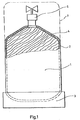
- FIG. 1 shows an exemplary embodiment of a gas container according to the invention designed as a propane gas bottle.
- the actual container 1 is produced by welding a circular cylindrical pot-shaped lower part to a circular cover part.
- the walls 2 of the container 1 consist of the aluminum alloy AIMgSi1.
- At the lower end of the container an annular foot 3 is attached, which is made of the same material.
- a heat-conducting filler insert 4 made of a metallic spatial lattice, which in the present example also consists of the aluminum alloy AIMgSi1.
- the spatial lattice work is shown schematically in FIG. 1 by a bevy of oblique lines and essentially fills the interior of the container 1.
- the lattice work is fixed relative to the container both in the axial and in the radial direction. A relative movement between the container and the filling insert which generates friction cannot therefore take place.
- Fig. 2 shows a section of an expanded metal made of AIMgSi1, which was produced from a film of 0.085 mm thickness by punching and stretching. The individual honeycomb openings of the expanded metal are visible in FIG.
- an expanded metal of this type is formed into a double winding arrangement, as will be explained in more detail below with reference to FIGS. 3 to 5.
- the filling insert acts as a heat-conducting and distributing spatial network, which immediately dissipates any local heat development by dissipating the heat over the entire filling insert area. This makes the filling insert a safety network that prevents and prevents the development of flames and explosions.
- connection valve 1 has a very low weight and it is simple and economical to manufacture and easy to handle. Due to their good flame retardancy and good explosion protection, the arrangement of pressure relief devices and additional valves next to the connection valve is not necessary.
- a removable cover 7 is provided on the upper part of the propane gas bottle, which is indicated in broken lines in FIG. 1.
- FIG. 3 and 5 show the design of the filling insert for an exemplary embodiment of a gas container according to the invention designed as a propane gas bottle.
- the filling insert is formed from two coils 8, 9 of expanded metal arranged one inside the other. The material of each of these coils corresponds to the material, as in the exemplary embodiment according to FIG. 2, of the material specified individually.
- the outer winding 8 (FIG. 3) and the inner winding 9 (FIG. 4) are each manufactured individually.
- the outer diameter of the outer roll (8) is adapted to the inner diameter of the container (12) to be filled by the filling insert so that the outer roll (8), after being introduced into the container (12), lies against the inner wall of the container with a certain intrinsic elasticity .
- the hollow cylindrical outer winding (8) Because of the relatively small “wall thickness” of the hollow cylindrical outer winding (8), it can also be introduced through relatively narrow openings, such as the opening 11 of the bottle 12 (FIG. 5), the cylindrical winding being temporarily used by bending or folding Its own elasticity is deformed and its outer diameter is reduced so that it can be inserted through the opening 11 into the interior of the bottle 12. As soon as the outer wrap 8 is in the interior of the bottle 12, it resumes its cylindrical shape under its own elasticity and expands again so far that it comes into contact with the inner wall of the bottle 12. The inner wrap 9 (FIG. 4) can subsequently be introduced into the bottle 12 through the opening 11. The outer diameter of the inner winding 9 is adapted to the inner diameter of the outer winding 8.
- the inner diameter of the inner winding (9) can be reduced to such an extent that it can be inserted through the opening 11 of the bottle 12 into the interior of the outer winding 8.
- a hollow tube 13 of small diameter can be provided in the center of the inner winding 9.
- a test tube or a dip tube can be inserted into such a cavity.
- both coils 8 and 9 are made of the same aluminum alloy AIMgSi1, from which the walls of the bottle 12 are formed, there is no corrosion potential between the two coils of the filling insert nor between the filling insert and the container. Both coils 8 and 9 are made of expanded metal from an AIMgSi film of 0.085 mm thickness.
- 6 shows a container designed as a propellant gas tank for motor vehicles.
- 6 has a substantially cylindrical shape.
- the filler insert of this container can consist of a wrap made of expanded metal.
- the container itself can be formed from two pot-shaped parts welded together.
- the expanded metal coil which is designed in its diameter so that it can be introduced into the interior of the container with slight deformation, is first inserted into one pot-like part of the container.
- the other pot-like part of the container is then pushed over the free-standing end of the roll until it comes to rest on the other pot-like part.
- the two pot-like parts are then welded around the circumference at their abutting edges.
- the cylindrical container is then completely filled by the filling insert designed as a winding.
- the aluminum alloy AIMgSi1 is an advantageous material for both the winding and the walls of the container.
- the coil can be made of expanded metal from a foil of 0.085 mm thickness.
- the length and diameter of the cylindrical LPG tank depend on the required tank capacity. For example, the length can be approximately 1200 mm and the outside diameter can be, for example, 200 to 300 mm.
- Gas containers according to the invention can be produced in different shapes and for a large range of capacities and can be used to store a large number of gases or liquid gases or flammable liquids. In addition to the storage of propane, storage of butane or methane can also be considered.
Landscapes
- Engineering & Computer Science (AREA)
- Mechanical Engineering (AREA)
- General Engineering & Computer Science (AREA)
- Filling Or Discharging Of Gas Storage Vessels (AREA)
- Glass Compositions (AREA)
- Crystals, And After-Treatments Of Crystals (AREA)
Claims (8)
Priority Applications (1)
| Application Number | Priority Date | Filing Date | Title |
|---|---|---|---|
| AT84104020T ATE39560T1 (de) | 1983-06-22 | 1984-04-10 | Gasbehaelter. |
Applications Claiming Priority (2)
| Application Number | Priority Date | Filing Date | Title |
|---|---|---|---|
| DE3322328 | 1983-06-22 | ||
| DE3322328A DE3322328A1 (de) | 1983-03-04 | 1983-06-22 | Gasbehaelter |
Publications (3)
| Publication Number | Publication Date |
|---|---|
| EP0129653A2 EP0129653A2 (fr) | 1985-01-02 |
| EP0129653A3 EP0129653A3 (en) | 1985-12-04 |
| EP0129653B1 true EP0129653B1 (fr) | 1988-12-28 |
Family
ID=6201995
Family Applications (1)
| Application Number | Title | Priority Date | Filing Date |
|---|---|---|---|
| EP84104020A Expired EP0129653B1 (fr) | 1983-06-22 | 1984-04-10 | Réservoir de gaz |
Country Status (2)
| Country | Link |
|---|---|
| EP (1) | EP0129653B1 (fr) |
| AT (1) | ATE39560T1 (fr) |
Families Citing this family (3)
| Publication number | Priority date | Publication date | Assignee | Title |
|---|---|---|---|---|
| US4699123A (en) * | 1985-09-27 | 1987-10-13 | The Schawbel Corporation | Portable heating appliance |
| EP0256239A1 (fr) * | 1986-08-07 | 1988-02-24 | EKSPLO KONTROL Patlamayi Önleyici Maddeler Sanayi ve Ticaret A.S. | Matière de remplissage pour un récipient pour empêcher les explosions |
| FR2654694B1 (fr) * | 1989-11-17 | 1995-04-28 | Wabco Westinghouse Equip Ferro | Dispositif de reservoir de pression et systeme de commande de freinage utilisant un tel dispositif. |
Family Cites Families (4)
| Publication number | Priority date | Publication date | Assignee | Title |
|---|---|---|---|---|
| DE2306682C3 (de) * | 1972-03-24 | 1975-05-15 | Aluminiumarugyar, Budapest | Aluminiumflasche zur Aufnahme von verflüssigtem Gas unter Druck |
| AU4373279A (en) * | 1978-02-07 | 1979-08-16 | Expanded Metal Co. Ltd., The | Containers |
| CA1150682A (fr) * | 1978-03-30 | 1983-07-26 | Andrew Szego | Garniture interne thermofuge pour contenants de liquides sous pression |
| GB2028129B (en) * | 1978-08-17 | 1983-02-02 | Explosafe Sa | Containers and packings therefor |
-
1984
- 1984-04-10 EP EP84104020A patent/EP0129653B1/fr not_active Expired
- 1984-04-10 AT AT84104020T patent/ATE39560T1/de not_active IP Right Cessation
Also Published As
| Publication number | Publication date |
|---|---|
| ATE39560T1 (de) | 1989-01-15 |
| EP0129653A3 (en) | 1985-12-04 |
| EP0129653A2 (fr) | 1985-01-02 |
Similar Documents
| Publication | Publication Date | Title |
|---|---|---|
| DE3322328A1 (de) | Gasbehaelter | |
| DE112004000261B4 (de) | Doppelwandiges Behältnis für kryogene Flüssigkeiten | |
| DE9116330U1 (de) | Quetschkupplung für flexible Schläuche | |
| CH638447A5 (de) | Nahtloser behaelter aus metall. | |
| DE3644364A1 (de) | Einrichtung zur erwaermung von fluiden in speichertanks und transportroehren | |
| DE1486285A1 (de) | Behaelter | |
| DE2020062A1 (de) | Explosions-Entlastungsventil | |
| DE3435457A1 (de) | Fluessigkeits- und/oder gasbehaelter mit explosionshemmender und verbrennungseinschraenkender waermeleitender einlage | |
| DE3533406C2 (fr) | ||
| CH681616A5 (fr) | ||
| DE2361360A1 (de) | Fluessiggasbehaelter | |
| EP0129653A2 (fr) | Réservoir de gaz | |
| DE102017114810A1 (de) | Umhüllungseinheit, insbesondere für thermisch zu dämmende Körper | |
| EP1874575A2 (fr) | Recipient modulaire pour liquides cryogenes | |
| DE3307797A1 (de) | Gasbehaelter | |
| AT391301B (de) | Brauchwasserspeicher | |
| DE3011426A1 (de) | Kunststoff-waermespeicher, insbesondere fuer die warmwasserspeicherung im haustechnischen bereich u.dgl., sowie verfahren zu seiner hertellung | |
| DE3000092C2 (fr) | ||
| DE3421095C2 (de) | Dämpfungshalterung, insbesondere für dynamischen Belastungen und beträchtlichen Temperaturschwankungen ausgesetzte dünnwandige Rohrleitungen | |
| DE4243295A1 (de) | Flexibler Packgutschutz | |
| DE2449920C2 (de) | Vorrichtung zur Abgabe von Flüssigkeit | |
| DE2843591A1 (de) | Thermische isolation fuer rohre und verfahren zum herstellen einer solchen isolation | |
| EP0458049A2 (fr) | Corps creux pour transporter un fluide, et son application | |
| DE731735C (de) | Als Verdampfer ausgebildeter Einsatzkasten | |
| DE4339830C2 (de) | Wärmedämmung eines Kugeltanks zur Aufnahme tiefkalter Flüssigkeiten |
Legal Events
| Date | Code | Title | Description |
|---|---|---|---|
| PUAI | Public reference made under article 153(3) epc to a published international application that has entered the european phase |
Free format text: ORIGINAL CODE: 0009012 |
|
| AK | Designated contracting states |
Designated state(s): AT BE CH FR IT LI LU NL |
|
| PUAL | Search report despatched |
Free format text: ORIGINAL CODE: 0009013 |
|
| AK | Designated contracting states |
Designated state(s): AT BE CH FR IT LI LU NL |
|
| 17P | Request for examination filed |
Effective date: 19860530 |
|
| 17Q | First examination report despatched |
Effective date: 19870820 |
|
| GRAA | (expected) grant |
Free format text: ORIGINAL CODE: 0009210 |
|
| ITF | It: translation for a ep patent filed | ||
| AK | Designated contracting states |
Kind code of ref document: B1 Designated state(s): AT BE CH FR IT LI LU NL |
|
| PG25 | Lapsed in a contracting state [announced via postgrant information from national office to epo] |
Ref country code: NL Effective date: 19881228 |
|
| REF | Corresponds to: |
Ref document number: 39560 Country of ref document: AT Date of ref document: 19890115 Kind code of ref document: T |
|
| ET | Fr: translation filed | ||
| ITTA | It: last paid annual fee | ||
| PG25 | Lapsed in a contracting state [announced via postgrant information from national office to epo] |
Ref country code: LU Free format text: LAPSE BECAUSE OF NON-PAYMENT OF DUE FEES Effective date: 19890430 Ref country code: LI Effective date: 19890430 Ref country code: CH Effective date: 19890430 Ref country code: BE Effective date: 19890430 |
|
| PGFP | Annual fee paid to national office [announced via postgrant information from national office to epo] |
Ref country code: FR Payment date: 19890614 Year of fee payment: 6 |
|
| NLV1 | Nl: lapsed or annulled due to failure to fulfill the requirements of art. 29p and 29m of the patents act | ||
| PGFP | Annual fee paid to national office [announced via postgrant information from national office to epo] |
Ref country code: AT Payment date: 19890627 Year of fee payment: 6 |
|
| BERE | Be: lapsed |
Owner name: POSCHINGER UDO Effective date: 19890430 |
|
| PLBE | No opposition filed within time limit |
Free format text: ORIGINAL CODE: 0009261 |
|
| STAA | Information on the status of an ep patent application or granted ep patent |
Free format text: STATUS: NO OPPOSITION FILED WITHIN TIME LIMIT |
|
| REG | Reference to a national code |
Ref country code: CH Ref legal event code: PL |
|
| 26N | No opposition filed | ||
| PG25 | Lapsed in a contracting state [announced via postgrant information from national office to epo] |
Ref country code: AT Effective date: 19900410 |
|
| PG25 | Lapsed in a contracting state [announced via postgrant information from national office to epo] |
Ref country code: FR Effective date: 19901228 |
|
| REG | Reference to a national code |
Ref country code: FR Ref legal event code: ST |