EP0129708A1 - Mit Phasenmodulation arbeitendes Regelsystem für eine Magnetplattendatei - Google Patents
Mit Phasenmodulation arbeitendes Regelsystem für eine Magnetplattendatei Download PDFInfo
- Publication number
- EP0129708A1 EP0129708A1 EP84105756A EP84105756A EP0129708A1 EP 0129708 A1 EP0129708 A1 EP 0129708A1 EP 84105756 A EP84105756 A EP 84105756A EP 84105756 A EP84105756 A EP 84105756A EP 0129708 A1 EP0129708 A1 EP 0129708A1
- Authority
- EP
- European Patent Office
- Prior art keywords
- fields
- phase
- constant frequency
- field
- transitions
- Prior art date
- Legal status (The legal status is an assumption and is not a legal conclusion. Google has not performed a legal analysis and makes no representation as to the accuracy of the status listed.)
- Granted
Links
- 230000010363 phase shift Effects 0.000 claims abstract description 19
- 238000006073 displacement reaction Methods 0.000 claims abstract description 14
- 230000007704 transition Effects 0.000 claims description 26
- 230000008859 change Effects 0.000 claims description 9
- 238000013500 data storage Methods 0.000 abstract 1
- 238000000034 method Methods 0.000 description 5
- 101000606504 Drosophila melanogaster Tyrosine-protein kinase-like otk Proteins 0.000 description 4
- 239000013078 crystal Substances 0.000 description 4
- 230000000694 effects Effects 0.000 description 3
- 238000005259 measurement Methods 0.000 description 3
- 230000004044 response Effects 0.000 description 3
- 238000012935 Averaging Methods 0.000 description 2
- 230000001427 coherent effect Effects 0.000 description 2
- 230000001360 synchronised effect Effects 0.000 description 2
- 230000004075 alteration Effects 0.000 description 1
- 238000013459 approach Methods 0.000 description 1
- 230000001419 dependent effect Effects 0.000 description 1
- 238000001514 detection method Methods 0.000 description 1
- 238000010586 diagram Methods 0.000 description 1
- 239000006249 magnetic particle Substances 0.000 description 1
- 230000005415 magnetization Effects 0.000 description 1
- 230000004048 modification Effects 0.000 description 1
- 238000012986 modification Methods 0.000 description 1
- 230000000737 periodic effect Effects 0.000 description 1
- 230000008569 process Effects 0.000 description 1
- 230000002250 progressing effect Effects 0.000 description 1
- 230000003252 repetitive effect Effects 0.000 description 1
- 230000002441 reversible effect Effects 0.000 description 1
- 238000000638 solvent extraction Methods 0.000 description 1
- 230000009897 systematic effect Effects 0.000 description 1
Images

Classifications
-
- G—PHYSICS
- G11—INFORMATION STORAGE
- G11B—INFORMATION STORAGE BASED ON RELATIVE MOVEMENT BETWEEN RECORD CARRIER AND TRANSDUCER
- G11B5/00—Recording by magnetisation or demagnetisation of a record carrier; Reproducing by magnetic means; Record carriers therefor
- G11B5/48—Disposition or mounting of heads or head supports relative to record carriers ; arrangements of heads, e.g. for scanning the record carrier to increase the relative speed
- G11B5/54—Disposition or mounting of heads or head supports relative to record carriers ; arrangements of heads, e.g. for scanning the record carrier to increase the relative speed with provision for moving the head into or out of its operative position or across tracks
- G11B5/55—Track change, selection or acquisition by displacement of the head
- G11B5/5521—Track change, selection or acquisition by displacement of the head across disk tracks
- G11B5/5526—Control therefor; circuits, track configurations or relative disposition of servo-information transducers and servo-information tracks for control thereof
-
- G—PHYSICS
- G11—INFORMATION STORAGE
- G11B—INFORMATION STORAGE BASED ON RELATIVE MOVEMENT BETWEEN RECORD CARRIER AND TRANSDUCER
- G11B21/00—Head arrangements not specific to the method of recording or reproducing
- G11B21/02—Driving or moving of heads
- G11B21/10—Track finding or aligning by moving the head ; Provisions for maintaining alignment of the head relative to the track during transducing operation, i.e. track following
- G11B21/106—Track finding or aligning by moving the head ; Provisions for maintaining alignment of the head relative to the track during transducing operation, i.e. track following on disks
-
- G—PHYSICS
- G11—INFORMATION STORAGE
- G11B—INFORMATION STORAGE BASED ON RELATIVE MOVEMENT BETWEEN RECORD CARRIER AND TRANSDUCER
- G11B5/00—Recording by magnetisation or demagnetisation of a record carrier; Reproducing by magnetic means; Record carriers therefor
- G11B5/48—Disposition or mounting of heads or head supports relative to record carriers ; arrangements of heads, e.g. for scanning the record carrier to increase the relative speed
- G11B5/58—Disposition or mounting of heads or head supports relative to record carriers ; arrangements of heads, e.g. for scanning the record carrier to increase the relative speed with provision for moving the head for the purpose of maintaining alignment of the head relative to the record carrier during transducing operation, e.g. to compensate for surface irregularities of the latter or for track following
- G11B5/596—Disposition or mounting of heads or head supports relative to record carriers ; arrangements of heads, e.g. for scanning the record carrier to increase the relative speed with provision for moving the head for the purpose of maintaining alignment of the head relative to the record carrier during transducing operation, e.g. to compensate for surface irregularities of the latter or for track following for track following on disks
- G11B5/59605—Circuits
- G11B5/59616—Synchronisation; Clocking
-
- G—PHYSICS
- G11—INFORMATION STORAGE
- G11B—INFORMATION STORAGE BASED ON RELATIVE MOVEMENT BETWEEN RECORD CARRIER AND TRANSDUCER
- G11B5/00—Recording by magnetisation or demagnetisation of a record carrier; Reproducing by magnetic means; Record carriers therefor
- G11B5/48—Disposition or mounting of heads or head supports relative to record carriers ; arrangements of heads, e.g. for scanning the record carrier to increase the relative speed
- G11B5/58—Disposition or mounting of heads or head supports relative to record carriers ; arrangements of heads, e.g. for scanning the record carrier to increase the relative speed with provision for moving the head for the purpose of maintaining alignment of the head relative to the record carrier during transducing operation, e.g. to compensate for surface irregularities of the latter or for track following
- G11B5/596—Disposition or mounting of heads or head supports relative to record carriers ; arrangements of heads, e.g. for scanning the record carrier to increase the relative speed with provision for moving the head for the purpose of maintaining alignment of the head relative to the record carrier during transducing operation, e.g. to compensate for surface irregularities of the latter or for track following for track following on disks
- G11B5/59627—Aligning for runout, eccentricity or offset compensation
Definitions
- This invention relates to transducer positioning and more particularly to phase modulated servo systems for accessing and following data tracks on a rotating medium.
- the accepted method of determining transducer position is through an amplitude measurement of signals from adjoining servo tracks to generate a net signal indicative of the radial displacement from a predetermined track centerline.
- track densities have increased, the capability of this technique has been enlarged by progressing from dibit to tribit to pentabit servo formats to increase the number of tracks in the capture area and enable more precise track identification. Any of these techniques has been susceptible to inaccuracy as a result of random electrical noise occurring during the servo signal window, and to mitigate this disability, the servo format has often used redundant signals which are averaged to obtain a more uniform approximation to the true value.
- servo information is encoded in the phase of several constant frequency fields within the servo pattern.
- a linear phase change would be optimum, but practical limitations often require that a pattern be used that closely simulates a linear change relationship.
- the phase of each field changes by a fixed amount N times per track so as so approximate a linear change in phase with transducer radial position using a pattern which can be written with a conventional magnetic recording head. All of the variable phase servo fields are written with the same frequency so that the frequency response of the read/write head and the data channel will not effect the position error signals.
- the number of cycles within each • • field is arbitrary except that with more cycles it is possible to average the phase measurement over more transitions and reduce the influence of noise signals.
- Phase is measured modulo 360°.
- the phase of a given field will go through 360° every M tracks.
- Several fields can be used having different values of M to obtain coarse, medium and fine position resolution with the same servo pattern and demodulation scheme.
- This servo pattern is less susceptible to track-type dependent squeeze than previous servo patterns. Different frequency and phase contents of the signals written on odd or even tracks in the tribit servo pattern cause unpredictable amounts of squeeze between adjacent tracks.
- the pentabit servo pattern has four track types, each having different frequency and phase content.
- the servo information is encoded at a single frequency so that frequency response of the head cannot affect the position error signal to first order.
- the context for every field in the servo pattern is the same at every track position so that the off-track pickup from the sides of the read/write gap cannot cause squeeze between adjacent tracks. Since the amplitude of the off-track pickup is reduced rapidly as the frequency is raised, it is clearly advantageous to use many cycles at a fairly high frequency to minimize squeeze effects due to off-track pickup.
- servo information is encoded in the phase of the servo pattern instead of the amplitude of the servo signal lobes. Further, the impact of random noise in the media has less influence when averaging many transitions rather than using one or a few peaks. Also amplitude should have reduced importance to render the automatic gain control (AGC) function less critical.
- AGC automatic gain control
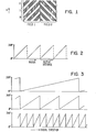
- Figure 1 shows an idealized phase shift servo position with the concentric tracks represented horizontally and radial position represented as vertical movement.
- One polarity of the magnetic particles within the servo area is shown in the form of shaded portions with unshaded portions being the reverse polarity.
- the figure shows two fields written at the same frequency. Since the polarity has two transitions per track, a transducer head greater than half the track pitch will encounter a change of phase associated with radial displacement that changes both continuously and linearly with such radial displacement.
- a clock or signal source running at the same frequency as the two fields and a means for detecting the phase of each field with respect to the clock.
- the phase difference between the fields gives the radial position of the transducer modulo some number of tracks, which number of tracks may be an integer or a non-integer.
- the repeat distance may be any distance that equal 160° of phase difference. This distance in tracks is chosen with respect to the desired function subject to noise and hardware performance considerations.
- the use of three fields enables the use of three different repeat distances corresponding to the phase differences between various interfield differences, to allow the position to be unambiguously detected on three different scales of distances (coarse, medium and fine). For sector servo applications, these multiple degrees of resolution will be especially useful in seek mode.
- transition pattern shown in figure 1 is optimal in providing a continuous and linear phase change with radial movement of the transducer, the problems associated with writing the pattern make a modified form that provides good performance a more practical resolution of the problem.
- the pattern be written with slanted transitions in order to obtain good performance provided the head or channel filters out the third and higher harmonics of the signal frequency.
- the head or channel filters out the third and higher harmonics of the signal frequency.
- the position error signal is encoded as a phase difference between two patterns written on the disk.
- Figure 4 shows phase displacement of the pattern occurring each half-track. The phase displacement as shown is equal in both fields but occurs in opposite circumferential directions.
- the pattern shows a displacement D between the centers of the two fields whose phases are being compared.
- the demodulator which processes the signal uses the signal produced by the magnetic recording head to determine the radial position of the head.
- the head signal consist of two periodic sequences of transitions produced as the head traverse the patterns of the two fields in the circumferential direction at almost constant radial displacement.
- the demodulator measures the relative phase difference between the average phase in field 1 and the average phase in field 2 by comparing both to a common reference clock whose transitions are coherent over both fields. This reference clock is obtained by dividing down a higher frequency crystal clock whose transitions are not necessarily synchronized with the transitions in the head signal.
- the demodulator output consists of a difference of the phase of field 1 minus the phase of the difference and the phase of field 2 minus the phase of the reference.
- the phase of the reference clock cancels out.
- the phase error in radians will be the product of the difference between the pattern and reference frequencies in radians per second times the displacement between the centers of the fields in meters divided by the disk surface velocity under ' the head in meters per second.
- the frequency differences causing the errors might arise from spindle speed variations between the time the signals were written on the disk surface and later readback or from different frequencies being used to write and later demodulate the servo information.
- P ⁇ his source of error may be greatly reduced by minimizing the effective displacement between the centers of the two fields. This is done by splitting one of the two fields into two subfields equally distant on either side of the other field. Thus the centers of mass of the two fields coincide causing the error term to vanish.
- the key is that the fields may be divided into multiple subfields and that it is the displacement between the centers of mass of the fields that determines the error.
- Figure 5 illustrates the simplest pattern which reduces the error term to zero although clearly many other more complex patterns could be devised using the same principle.
- Figure 5 shows a two field pattern wherein field 1 has been partitioned into subfields A and B which are respectively uniformly positioned before and after field 2. The centers of mass of the fields now coincide, and the phase error is eliminated.
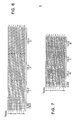
- Figure 6 shows one possible implementation of a servo pattern for a file with the motor speed synchronized to a crystal clock, that is known frequency.
- the showings of figures 6 and 7 show rectangular areas having a half track width with one polarity shown by dotted rectangles and the opposite polarity as open rectangles.
- the clock field allows recognition of the boundaries of the remaining fields for gating.
- the phase difference between fields 1 and 2 repeats (360° of phase difference) every eight tracks for use in seek mode.
- the difference between fields 2 and 3 repeats every track for track follow error signal.
- phase shifted servo track portions should have a radial width no greater than the width of the transducer head.
- phase modulated servo technique is capable of a wide range of degrees of resolution through modification of the number of tracks during which the page goes through 360° of phase shift in the various fields and the use of the initial clock field with unchanging phase as one of the fields used to obtain a phase difference value.
- phase shift alterations in a servo using three phase shifted fields a range of low, intermediate and high resolution can be readily produced such as 16 tracks, 4 tracks and 1 track or 64 tracks, 8 tracks and 1 track.
- Figure 7 illustrates the split burst approach to eliminate speed variation errors or irregularities wherein two phase • shifted servo fields are used with common centers achieved by partitioning the first field into subfields disposed at opposite sides of the other field (field 2). This illustrates 360° over an eight track radial distance with the phase shifting in one-half track radial increments.
- Figure 8 shows a typical phase demodulator for obtaining a position signal from two constant frequency servo fields having radially varying phase.
- the analog signal from the transducer head is received on line 10 and is converted by filter 11 and comparator 12 to a digital signal on line 13.
- the servo ID detector 14 identifies a servo sector, whereupon window and timing signal generator 15 creates the windows for the radially varying phase constant frequency servo fields.
- the crystal clock circuit 16 outputs a signal with the same frequency as the constant frequency servo fields.
- phase of the crystal clock signal on line 17 is compared with the phase of the digital signal for each of the constant frequency servo fields and the difference between the compared values derived from the two fields is ascertained by the phase difference processor 19 to produce a position signal one line 20 which is indicative of the transducer position within the radial distance encompassed by 360° of phase difference.
Landscapes
- Moving Of The Head To Find And Align With The Track (AREA)
- Moving Of Head For Track Selection And Changing (AREA)
Applications Claiming Priority (2)
| Application Number | Priority Date | Filing Date | Title |
|---|---|---|---|
| US507647 | 1983-06-27 | ||
| US06/507,647 US4549232A (en) | 1983-06-27 | 1983-06-27 | Phase modulated servo system |
Publications (2)
| Publication Number | Publication Date |
|---|---|
| EP0129708A1 true EP0129708A1 (de) | 1985-01-02 |
| EP0129708B1 EP0129708B1 (de) | 1989-10-11 |
Family
ID=24019546
Family Applications (1)
| Application Number | Title | Priority Date | Filing Date |
|---|---|---|---|
| EP84105756A Expired EP0129708B1 (de) | 1983-06-27 | 1984-05-21 | Mit Phasenmodulation arbeitendes Regelsystem für eine Magnetplattendatei |
Country Status (5)
| Country | Link |
|---|---|
| US (1) | US4549232A (de) |
| EP (1) | EP0129708B1 (de) |
| JP (1) | JPS6010472A (de) |
| DE (1) | DE3480131D1 (de) |
| SG (1) | SG25591G (de) |
Cited By (7)
| Publication number | Priority date | Publication date | Assignee | Title |
|---|---|---|---|---|
| EP0207692A3 (en) * | 1985-06-28 | 1989-04-12 | International Business Machines Corporation | A servo control system for centring a transducer head on a data track on a magnetic record |
| EP0480574A3 (en) * | 1990-09-07 | 1993-04-14 | International Business Machines Corporation | Optical data storage system with sector servo |
| GB2286481A (en) * | 1994-02-10 | 1995-08-16 | Ibm | Method and apparatus for servo positioning in a direct access storage device |
| EP0645764A3 (de) * | 1993-09-23 | 1996-09-11 | Ibm | Verfahren und Vorrichtung zur Positionnierung mittels Phasenmodulation in einer Speichereinheit mit direktem Zugriff. |
| US6529341B1 (en) | 1997-11-12 | 2003-03-04 | Matsushita Electric Industrial Co., Ltd. | Magnetic recording/reproduction device using preformat information |
| EP1593119A1 (de) * | 2003-02-14 | 2005-11-09 | Bill Richard Baker | Zusammengesetzte phasencodierung für druckservomuster |
| EP1942491A3 (de) * | 2006-12-28 | 2008-11-05 | Fujitsu Ltd. | Servomusterschreibvorrichtung, Servomusterschreibverfahren, Servomusterlesevorrichtung und Servomusterleseverfahren |
Families Citing this family (80)
| Publication number | Priority date | Publication date | Assignee | Title |
|---|---|---|---|---|
| US4642562A (en) * | 1984-06-27 | 1987-02-10 | International Business Machines Corporation | Phase difference demodulator |
| JP2914971B2 (ja) * | 1987-09-14 | 1999-07-05 | 株式会社日立製作所 | 磁気ディスク装置 |
| JPH0291866A (ja) * | 1988-09-28 | 1990-03-30 | Nec Corp | 磁気ディスク装置 |
| KR950008751B1 (ko) * | 1988-11-30 | 1995-08-04 | 엘지전자주식회사 | 자기 디스크 기록 장치에서 트랙 중심을 찾는 장치 및 방법 |
| US5343340A (en) * | 1992-12-31 | 1994-08-30 | International Business Machines Corporation | Digital servo signal demodulation method and apparatus utilizing a partial-response maximum-likelihood (PRML) channel in a disk file |
| US5424881A (en) | 1993-02-01 | 1995-06-13 | Cirrus Logic, Inc. | Synchronous read channel |
| JP3313175B2 (ja) * | 1993-02-19 | 2002-08-12 | 富士通株式会社 | ディスク装置のサーボ位置検出装置及びその方法 |
| US5608587A (en) * | 1993-08-06 | 1997-03-04 | Seagate Technology, Inc. | Method using magnetic disk servo pattern with buried identification patterns |
| US5694265A (en) * | 1994-04-19 | 1997-12-02 | Fujitsu Limited | Disk apparatus for detecting position of head by reading phase servo pattern |
| US5689384A (en) * | 1994-06-30 | 1997-11-18 | International Business Machines Corporation | Timing based servo system for magnetic tape systems |
| US5615065A (en) * | 1994-10-04 | 1997-03-25 | International Business Machines Corporation | Phase-compensated servo pattern and position error-sensing detector |
| JP3642821B2 (ja) * | 1995-03-17 | 2005-04-27 | 富士通株式会社 | 磁気ヘッドスライダ |
| US5600506A (en) * | 1995-05-10 | 1997-02-04 | Conner Peripherals, Inc. | Apparatus and method for determining the position of a transducer relative to a disk surface in a disk drive system |
| JP3245343B2 (ja) * | 1995-12-28 | 2002-01-15 | 富士通株式会社 | ディスク装置及びディスク装置用位相復調装置並びにディスク装置の位相復調方法 |
| KR100274522B1 (ko) * | 1996-03-14 | 2001-01-15 | 니시무로 타이죠 | 멀티자기헤드및이것을구비한자기디스크장치 |
| US6014283A (en) * | 1997-05-15 | 2000-01-11 | Western Digital Corporation | Non-quadrature servo burst pattern for micro-jogging a magnetoresistive head in a magnetic disk drive |
| US5930065A (en) * | 1997-05-16 | 1999-07-27 | International Business Machines Corporation | Timing based servo longitudinal addressing |
| JP3013892B2 (ja) | 1997-06-26 | 2000-02-28 | 日本電気株式会社 | ヘッド位置信号復調装置及びこれを利用したヘッド位置決め装置 |
| US5923272A (en) * | 1997-07-08 | 1999-07-13 | International Business Machines Corporation | Serial bitstream code for timing-based servo |
| US5966264A (en) * | 1997-08-07 | 1999-10-12 | International Business Machines Cororation | Two frequency servo PES pattern |
| US6025970A (en) * | 1997-08-07 | 2000-02-15 | International Business Machines Corporation | Digital demodulation of a complementary two-frequency servo PES pattern |
| JP2000100098A (ja) * | 1998-09-17 | 2000-04-07 | Fujitsu Ltd | サーボ情報書込方法及び記憶装置 |
| JP3340077B2 (ja) | 1998-11-30 | 2002-10-28 | 富士通株式会社 | サーボ制御方法及び情報記憶装置 |
| US6542325B1 (en) * | 1999-03-10 | 2003-04-01 | Imation Corp. | Time-based servo for magnetic storage media |
| US6278571B1 (en) * | 1999-05-19 | 2001-08-21 | International Business Machines Corporation | Adaptive servo gap detection for timing based servo |
| US6239939B1 (en) * | 1999-08-09 | 2001-05-29 | International Business Machines Corporation | Robust detection of data modulated into a timing based servo |
| JP2001110027A (ja) | 1999-10-08 | 2001-04-20 | Hitachi Ltd | 磁気記憶装置 |
| JP3877133B2 (ja) * | 2001-02-16 | 2007-02-07 | 富士通株式会社 | 信号再生方法及び記憶装置 |
| US6961203B1 (en) * | 2001-03-06 | 2005-11-01 | Maxtor Corporation | Hybrid printed servo patterns for magnetic media and hard disk systems implementing same |
| US7830630B2 (en) * | 2001-06-28 | 2010-11-09 | Stmicroelectronics, Inc. | Circuit and method for detecting the phase of a servo signal |
| US6781778B1 (en) * | 2001-07-16 | 2004-08-24 | Imation Corp. | Time-based sectored servo data format |
| US6754022B1 (en) | 2001-07-16 | 2004-06-22 | Imation Corp. | High-speed current driver |
| WO2003017276A1 (fr) * | 2001-08-10 | 2003-02-27 | Fujitsu Limited | Procede permettant de detecter une position, enregistreur/reproducteur d'informations et support d'enregistrement d'informations |
| US7072133B1 (en) | 2001-10-15 | 2006-07-04 | Imation Corp. | Servo mark verify head |
| US6859339B2 (en) * | 2002-01-31 | 2005-02-22 | Matsushita Electric Industrial Co., Ltd. | Master information magnetic recording apparatus and method for manufacturing magnetic recording medium in which information is recorded by using this |
| JP4080233B2 (ja) | 2002-05-07 | 2008-04-23 | 富士通株式会社 | 磁気記録装置および磁気記録媒体 |
| US6639529B1 (en) * | 2002-05-14 | 2003-10-28 | Mitutoyo Corporation | System and method for delay calibration in position encoders |
| US6826140B2 (en) * | 2002-08-26 | 2004-11-30 | Bae Systems Information And Electronic Systems Integration Inc | Multichannel digital recording system with multi-user detection |
| US7227714B2 (en) * | 2003-07-22 | 2007-06-05 | Matsushita Electric Industrial Co., Ltd. | Methods for conditional servowriting |
| US7106548B2 (en) * | 2003-07-22 | 2006-09-12 | Matsushita Electric Industrial Co., Ltd. | Methods for WORF improvement in conditional servowriting |
| US7522506B2 (en) * | 2003-11-03 | 2009-04-21 | Hewlett-Packard Development Company, L.P. | Memory |
| US7136251B2 (en) * | 2003-12-24 | 2006-11-14 | Matsushita Electric Industrial, Co., Ltd. | Methods for WORF improvement in conditional servowriting |
| US7206170B2 (en) * | 2004-05-19 | 2007-04-17 | Imetion Corp. | Thin film servo head apparatus with canted servo gaps |
| US7209314B2 (en) * | 2005-06-09 | 2007-04-24 | Hitachi Global Storage Technologies Netherlands B.V. | Disk drive with phase-quadrature servo pattern and demodulated position error signal insensitive to timing and phase-misalignment errors |
| US7440224B2 (en) * | 2006-01-23 | 2008-10-21 | Toshiba Corporation | Disk drive servo |
| US7721049B2 (en) * | 2006-03-27 | 2010-05-18 | Kabuhsiki Kaisha Toshiba | Disk drive write method |
| US20070279781A1 (en) * | 2006-05-31 | 2007-12-06 | Toshiba America Information Systems, Inc. | Channel training method and apparatus |
| US7453660B2 (en) * | 2006-05-31 | 2008-11-18 | Kabushiki Kaisha Toshiba | Shock feed forward adaptive filters |
| US7468859B2 (en) * | 2006-05-31 | 2008-12-23 | Kabushiki Kaisha Toshiba | Voice coil motor effective resistance determination |
| US7436616B2 (en) * | 2006-05-31 | 2008-10-14 | Toshiba Corporation | Current pulsing for unloading |
| US20070279782A1 (en) * | 2006-05-31 | 2007-12-06 | Rydhan Abdul R | Method and apparatus for determining offset between read and write transducers in a disk drive |
| US20070279790A1 (en) * | 2006-05-31 | 2007-12-06 | Tanner Brian K | Adjustable output voltage regulator for disk drive |
| US20070279788A1 (en) * | 2006-05-31 | 2007-12-06 | Toshiba America Information Systems, Inc. | Method and apparatus to perform defect scanning |
| US7457066B2 (en) * | 2006-05-31 | 2008-11-25 | Kabushiki Kiasha Toshiba | Method and apparatus for phase-shift null-burst-pattern |
| US7365929B2 (en) * | 2006-07-30 | 2008-04-29 | International Business Machines Corporation | Synchronous servo channel for tape drive systems |
| US7492540B2 (en) * | 2006-09-15 | 2009-02-17 | Hitachi Global Storage Technologies Netherlands B.V. | Apparatus system and method for variable data density patterned media |
| US20080144211A1 (en) * | 2006-12-18 | 2008-06-19 | Weber Mark P | Servo techniques that mitigate an effect of read and write velocity variations on position error signal calculations |
| US7495859B2 (en) * | 2007-02-20 | 2009-02-24 | Imation Corp. | Interleaved servo pattern |
| US7848039B2 (en) * | 2007-08-11 | 2010-12-07 | Hitachi Global Storage Technologies Netherlands B.V. | Magnetic recording disk and disk drive with patterned phase-type servo fields for read/write head positioning |
| US7848040B2 (en) * | 2007-08-17 | 2010-12-07 | Hitachi Global Storage Technologies Netherlands B.V. | Magnetic recording disk and disk drive with amplitude-type servo fields having patterned alternating-polarity servo islands for read/write head positioning |
| US7612961B2 (en) * | 2007-10-12 | 2009-11-03 | Hitachi Global Storage Technologies Netherlands B.V. | Magnetic recording disk and disk drive with patterned phase-type servo fields for read/write head positioning |
| US7729073B2 (en) * | 2007-10-12 | 2010-06-01 | Hitachi Global Storage Technologies Netherlands B.V. | Magnetic recording disk and disk drive with amplitude-type servo fields having patterned servo islands for read/write head positioning |
| US7944643B1 (en) * | 2007-12-05 | 2011-05-17 | Wd Media, Inc. | Patterns for pre-formatted information on magnetic hard disk media |
| JP4868422B2 (ja) * | 2008-08-29 | 2012-02-01 | 東芝ストレージデバイス株式会社 | 磁気記憶媒体および磁気記憶媒体駆動装置 |
| US7880992B2 (en) * | 2008-09-02 | 2011-02-01 | Seagate Technology Llc | Phase detector that compensates for frequency variation induced bias in phases of servo burst fields |
| US8824079B2 (en) * | 2008-09-15 | 2014-09-02 | Seagate Technology Llc | Servo patterns for bit patterned media with multiple dots per servo period |
| US8947809B2 (en) | 2008-09-19 | 2015-02-03 | Seagate Technology Llc | Encoding scheme for bit patterned media |
| US7920354B2 (en) * | 2008-09-15 | 2011-04-05 | Seagate Technology Llc | Phase servo patterns for bit patterned media |
| US7916416B1 (en) | 2008-09-29 | 2011-03-29 | Western Digital Technologies, Inc. | Disk drive comprising slanted line servo bursts having a varying tilt angle |
| US7746594B1 (en) | 2008-09-29 | 2010-06-29 | Western Digital Technologies, Inc. | Disk drive comprising slanted line servo burst sets offset radially |
| US7746595B1 (en) | 2008-09-29 | 2010-06-29 | Western Digital Technologies, Inc. | Disk drive comprising slanted line servo bursts having reverse polarity segments |
| US9514775B2 (en) * | 2008-11-25 | 2016-12-06 | Seagate Technology Llc | Reducing effect of frequency acquisition error in a position error signal responsive to split servo burst patterns |
| US7995304B2 (en) * | 2009-05-27 | 2011-08-09 | Seagate Technology Llc | Circuits that use a postamble signal to determine phase and frequency errors in the acquisition of a preamble signal |
| US8059350B2 (en) * | 2009-10-22 | 2011-11-15 | Hitachi Global Storage Technologies Netherlands B.V. | Patterned magnetic recording disk with patterned servo sectors having chevron servo patterns |
| US8000048B2 (en) * | 2009-12-09 | 2011-08-16 | Hitachi Global Storage Technologies Netherlands B.V. | Magnetic recording disk and disk drive with track identification using phase-type servo patterns |
| JP2014059932A (ja) | 2012-09-19 | 2014-04-03 | Toshiba Corp | 磁気ディスク装置および復調位置補正方法 |
| US8625231B1 (en) * | 2012-11-08 | 2014-01-07 | HGST Netherlands B.V. | Adjusting VGA analog gain for misaligned servo sectors in a disk drive |
| US8848303B1 (en) | 2013-05-13 | 2014-09-30 | Kabushiki Kaisha Toshiba | Disk storage apparatus and method for servo demodulation |
| US8908303B1 (en) | 2013-07-30 | 2014-12-09 | Kabushiki Kaisha Toshiba | Method for servo demodulation and disk storage apparatus |
| CN104658555A (zh) | 2013-11-25 | 2015-05-27 | 株式会社东芝 | 头位置解调方法及磁盘装置 |
Citations (6)
| Publication number | Priority date | Publication date | Assignee | Title |
|---|---|---|---|---|
| DE2364174A1 (de) * | 1972-12-22 | 1974-07-25 | Vermont Res Corp | Vorrichtung zum positionieren eines signalwandlers auf eine spur eines aufzeichnungstraegers |
| DE2657642A1 (de) * | 1975-12-23 | 1977-07-07 | Ibm | Einstellvorrichtung fuer den zugriffsarm des magnetkopfes eines magnetplattenspeichers |
| DE2657266A1 (de) * | 1975-12-23 | 1977-07-07 | Ibm | Einstellvorrichtung fuer den zugriffsarm des magnetkopfes eines magnetplattenspeichers |
| US4087843A (en) * | 1975-12-23 | 1978-05-02 | International Business Machines Corporation | Positioning device for the access arm of the magnetic head of a magnetic disk storage |
| DE1524775B2 (de) * | 1966-03-02 | 1979-09-20 | International Business Machines Corp., Armonk, N.Y. (V.St.A.) | |
| DE2928311A1 (de) * | 1979-07-13 | 1981-02-05 | Basf Ag | Spurlageregelung fuer ein system zur aufzeichnung/wiedergabe von informationen auf einem magnetaufzeichnungstraeger, insbesondere einem flexiblen magnetaufzeichnungstraeger |
Family Cites Families (2)
| Publication number | Priority date | Publication date | Assignee | Title |
|---|---|---|---|---|
| US4405956A (en) * | 1981-04-22 | 1983-09-20 | Xerox Corporation | Tracking apparatus for read/write head |
| US4488188A (en) * | 1982-11-01 | 1984-12-11 | International Business Machines Corporation | Buried servo recording system using phase encoded servo pattern |
-
1983
- 1983-06-27 US US06/507,647 patent/US4549232A/en not_active Expired - Lifetime
-
1984
- 1984-03-19 JP JP59051302A patent/JPS6010472A/ja active Granted
- 1984-05-21 DE DE8484105756T patent/DE3480131D1/de not_active Expired
- 1984-05-21 EP EP84105756A patent/EP0129708B1/de not_active Expired
-
1991
- 1991-04-05 SG SG255/91A patent/SG25591G/en unknown
Patent Citations (6)
| Publication number | Priority date | Publication date | Assignee | Title |
|---|---|---|---|---|
| DE1524775B2 (de) * | 1966-03-02 | 1979-09-20 | International Business Machines Corp., Armonk, N.Y. (V.St.A.) | |
| DE2364174A1 (de) * | 1972-12-22 | 1974-07-25 | Vermont Res Corp | Vorrichtung zum positionieren eines signalwandlers auf eine spur eines aufzeichnungstraegers |
| DE2657642A1 (de) * | 1975-12-23 | 1977-07-07 | Ibm | Einstellvorrichtung fuer den zugriffsarm des magnetkopfes eines magnetplattenspeichers |
| DE2657266A1 (de) * | 1975-12-23 | 1977-07-07 | Ibm | Einstellvorrichtung fuer den zugriffsarm des magnetkopfes eines magnetplattenspeichers |
| US4087843A (en) * | 1975-12-23 | 1978-05-02 | International Business Machines Corporation | Positioning device for the access arm of the magnetic head of a magnetic disk storage |
| DE2928311A1 (de) * | 1979-07-13 | 1981-02-05 | Basf Ag | Spurlageregelung fuer ein system zur aufzeichnung/wiedergabe von informationen auf einem magnetaufzeichnungstraeger, insbesondere einem flexiblen magnetaufzeichnungstraeger |
Cited By (11)
| Publication number | Priority date | Publication date | Assignee | Title |
|---|---|---|---|---|
| EP0207692A3 (en) * | 1985-06-28 | 1989-04-12 | International Business Machines Corporation | A servo control system for centring a transducer head on a data track on a magnetic record |
| EP0480574A3 (en) * | 1990-09-07 | 1993-04-14 | International Business Machines Corporation | Optical data storage system with sector servo |
| EP0645764A3 (de) * | 1993-09-23 | 1996-09-11 | Ibm | Verfahren und Vorrichtung zur Positionnierung mittels Phasenmodulation in einer Speichereinheit mit direktem Zugriff. |
| CN1064168C (zh) * | 1993-09-23 | 2001-04-04 | 国际商业机器公司 | 用于相位调制伺服定位的方法和设备 |
| GB2286481A (en) * | 1994-02-10 | 1995-08-16 | Ibm | Method and apparatus for servo positioning in a direct access storage device |
| GB2286481B (en) * | 1994-02-10 | 1997-12-10 | Ibm | Method and apparatus for servo positioning in a direct access storage device |
| US6219197B1 (en) | 1994-02-10 | 2001-04-17 | International Business Machines Corporation | Method and apparatus for servo positioning in a direct access storage device with a transducer read element width greater than ⅓ and less than ½ width of a data cylinder |
| US6529341B1 (en) | 1997-11-12 | 2003-03-04 | Matsushita Electric Industrial Co., Ltd. | Magnetic recording/reproduction device using preformat information |
| EP1593119A1 (de) * | 2003-02-14 | 2005-11-09 | Bill Richard Baker | Zusammengesetzte phasencodierung für druckservomuster |
| EP1942491A3 (de) * | 2006-12-28 | 2008-11-05 | Fujitsu Ltd. | Servomusterschreibvorrichtung, Servomusterschreibverfahren, Servomusterlesevorrichtung und Servomusterleseverfahren |
| US7589929B2 (en) | 2006-12-28 | 2009-09-15 | Fujitsu Limited | Servo pattern writing apparatus, servo pattern writing method, servo pattern reading apparatus, and servo pattern reading method |
Also Published As
| Publication number | Publication date |
|---|---|
| DE3480131D1 (en) | 1989-11-16 |
| US4549232A (en) | 1985-10-22 |
| EP0129708B1 (de) | 1989-10-11 |
| JPS6010472A (ja) | 1985-01-19 |
| JPH0250550B2 (de) | 1990-11-02 |
| SG25591G (en) | 1991-06-21 |
Similar Documents
| Publication | Publication Date | Title |
|---|---|---|
| US4549232A (en) | Phase modulated servo system | |
| US4578723A (en) | Head positioning system with automatic gain control | |
| US4511938A (en) | Magnetizable recording disk and disk file employing servo sector head positioning | |
| US5771131A (en) | Tracking in hard disk drive using magnetoresistive heads | |
| US7298580B2 (en) | Magnetic recording medium and magnetic recording/reproducing apparatus | |
| US4101942A (en) | Track following servo system and track following code | |
| US4454549A (en) | Slant track sector servo | |
| US5615065A (en) | Phase-compensated servo pattern and position error-sensing detector | |
| US4488188A (en) | Buried servo recording system using phase encoded servo pattern | |
| JPH0760542B2 (ja) | 読取りヘッド位置を決定する方法および装置 | |
| JPH0660429A (ja) | 情報記録媒体およびトラッキング誤差検出装置 | |
| JPH04252415A (ja) | 磁気ディスクおよび磁気ディスク装置 | |
| JPH0714330A (ja) | ディスク | |
| Ragle et al. | Position sensing for high track density recording | |
| JPS6171480A (ja) | 磁気ヘツドの位置決め方式 | |
| JPS62185218A (ja) | 回転記録媒体及びそのヘツド位置決め方式 |
Legal Events
| Date | Code | Title | Description |
|---|---|---|---|
| PUAI | Public reference made under article 153(3) epc to a published international application that has entered the european phase |
Free format text: ORIGINAL CODE: 0009012 |
|
| AK | Designated contracting states |
Designated state(s): DE FR GB IT |
|
| 17P | Request for examination filed |
Effective date: 19841123 |
|
| 17Q | First examination report despatched |
Effective date: 19860319 |
|
| D17Q | First examination report despatched (deleted) | ||
| GRAA | (expected) grant |
Free format text: ORIGINAL CODE: 0009210 |
|
| AK | Designated contracting states |
Kind code of ref document: B1 Designated state(s): DE FR GB IT |
|
| REF | Corresponds to: |
Ref document number: 3480131 Country of ref document: DE Date of ref document: 19891116 |
|
| ET | Fr: translation filed | ||
| ITF | It: translation for a ep patent filed | ||
| PLBE | No opposition filed within time limit |
Free format text: ORIGINAL CODE: 0009261 |
|
| STAA | Information on the status of an ep patent application or granted ep patent |
Free format text: STATUS: NO OPPOSITION FILED WITHIN TIME LIMIT |
|
| 26N | No opposition filed | ||
| ITTA | It: last paid annual fee | ||
| PGFP | Annual fee paid to national office [announced via postgrant information from national office to epo] |
Ref country code: FR Payment date: 19960507 Year of fee payment: 13 |
|
| PG25 | Lapsed in a contracting state [announced via postgrant information from national office to epo] |
Ref country code: FR Free format text: LAPSE BECAUSE OF NON-PAYMENT OF DUE FEES Effective date: 19980130 |
|
| REG | Reference to a national code |
Ref country code: FR Ref legal event code: ST |
|
| PGFP | Annual fee paid to national office [announced via postgrant information from national office to epo] |
Ref country code: DE Payment date: 19980522 Year of fee payment: 15 |
|
| PG25 | Lapsed in a contracting state [announced via postgrant information from national office to epo] |
Ref country code: DE Free format text: LAPSE BECAUSE OF NON-PAYMENT OF DUE FEES Effective date: 20000301 |
|
| PGFP | Annual fee paid to national office [announced via postgrant information from national office to epo] |
Ref country code: GB Payment date: 20000427 Year of fee payment: 17 |
|
| PG25 | Lapsed in a contracting state [announced via postgrant information from national office to epo] |
Ref country code: GB Free format text: LAPSE BECAUSE OF NON-PAYMENT OF DUE FEES Effective date: 20010521 |
|
| GBPC | Gb: european patent ceased through non-payment of renewal fee |
Effective date: 20010521 |