EP0130081A2 - Appareil pour le traitement de documents de valeur - Google Patents
Appareil pour le traitement de documents de valeur Download PDFInfo
- Publication number
- EP0130081A2 EP0130081A2 EP84304323A EP84304323A EP0130081A2 EP 0130081 A2 EP0130081 A2 EP 0130081A2 EP 84304323 A EP84304323 A EP 84304323A EP 84304323 A EP84304323 A EP 84304323A EP 0130081 A2 EP0130081 A2 EP 0130081A2
- Authority
- EP
- European Patent Office
- Prior art keywords
- bill
- bills
- receipt
- box
- pool
- Prior art date
- Legal status (The legal status is an assumption and is not a legal conclusion. Google has not performed a legal analysis and makes no representation as to the accuracy of the status listed.)
- Granted
Links
Images








Classifications
-
- G—PHYSICS
- G07—CHECKING-DEVICES
- G07D—HANDLING OF COINS OR VALUABLE PAPERS, e.g. TESTING, SORTING BY DENOMINATIONS, COUNTING, DISPENSING, CHANGING OR DEPOSITING
- G07D11/00—Devices accepting coins; Devices accepting, dispensing, sorting or counting valuable papers
- G07D11/40—Device architecture, e.g. modular construction
Definitions
- the present invention relates to an apparatus for dealing with bills, such as an automatic machine for withdrawing money from a bank or a bill counter.
- An automatic machine for withdrawing money from the bank in which the user inserts a treated card (memory medium) into the machine, inputs the amount of money to be withdrawn by pushing buttons of the keyboard of the machine, and then receives the requested amount of money from the machine.
- a treated card memory medium
- Machines of this kind usually comprise: a means for reading data magnetically or electrically recorded in the memory medium, such as a card reader; a means for displaying the input data input by the user and teaching the user the next procedure for operating the machine; a means for inputting the amount of money required and the identification code of the user, such as a keyboard; a bill dispenser comprising (bank notes) bill boxes housing bills/and a bill counter for counting bills withdrawn from the bill boxes; and a means for issuing a receipt on which accounting items such as the data, amount withdrawn, and the amount remaining in the account are printed.
- the level of the keyboard and the discharge box in which bills to be withdrawn are placed is limited to within a range wherein users can easily operate the machine.
- the bill dispenser includes the bill boxes and is large and heavy. Therefore, in a conventional automatic machine of this kind, only the bill dispenser is disposed below the discharge box or keyboard while the other equipment such as the card reader and the receipt issuing means are disposed above those units. Such a construction makes the machine overlarge and of an unwieldly height. Also, since the receipt is preferably discharged simultaneously with the bills from the discharge box, the receipt must be placed on the bills within the machine. Therefore, the arrangement of the discharge routes of the receipt and the bills is complicated, which also makes the construction of the machine overlarge.
- An embodiment of the present invention can provide an apparatus for dealing with bills having a compact construction by obviating the above-mentioned problems.
- An embodiment of the present invention can provide an apparatus for dealing with bills comprising a bill dispenser compactly and operationally combined with a receipt issuing means.
- An embodiment of the present invention can also provide an apparatus for dealing with bills in which the receipt and bills are conveniently made available to the user (bank notes)
- An apparatus for dealing with bills/in accordance with the present invention comprises: a plurality of bill boxes for containing different denominations of bills; means for withdrawing bills one by one from each bill box; a bill pool for temporarily storing bills fed from the bill boxes; means for discharging bills stored in the bill pool out of the apparatus through a discharge portion; means for reading a memory medium introduced into the apparatus by a user; means for inputting a desired withdrawal amount; means for rejecting discharge of the bills placed in the bill pool and retaining the rejected bills within the apparatus; and means for issuing a receipt.
- a plurality of bill boxes are disposed vertically one above the other; a common conveyor route is provided for conveying bills from each bill box to the bill pool; the uppermost bill box communicates with the rejecting means and receives the rejected bills within the end portion thereof; the receipt issuing means is disposed below the lowest bill box and connected to the common conveyor route so that the receipt is transported to the bill pool through the common conveyor route and discharged from the discharge portion together with the bills.
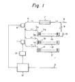
- FIG. 1 An explanation of the essential principle of the present invention is illustrated in Fig. 1.
- Bill boxes 1A (bank notes) and 1B which contain different denominations of bills/3a and 3b, respectively, are stacked vertically one above the other.
- a withdrawal means (not shown) withdraws a single bill from one of the bill boxes 1A and 1B.
- the withdrawn bill fed from each bill box lA or 1B is conveyed along a feeding route 5a or 5b to a common conveyor route 5, as shown by arrows, by conveyor belts (not shown).
- a detection means 6 for checking whether or not the correct bill has been withdrawn is disposed on the common conveyor route 5.
- the checked bill is transported to a bill pool 7 where the bill is temporarily stored.
- the detection means 6 detects that an incorrect bill has been transported or that been two single bills are superimposed and have/ transported simultaneously, the bill or bills are guided to a rejected bill receiver portion 10 located at the rear end of the upper bill box lA, together with bills which were stored in the bill pool 7, through a reject route 9.
- a receipt box 2 which contains receipts 4 having a size similar to the bills is disposed below the lower bill box 1B.
- a single receipt 4 is withdrawn from the receipt box 2 by a withdrawing means (not shown) and conveyed through a receipt route 14 to the common conveyor route 5.
- a printer unit 11 for printing on the receipt 4 is disposed on the receipt route 14.
- a signal S signifying the amount withdrawn and the identification number of the magnetic card of the user is input to a control circuit 12 by a keyboard (not shown).
- the result of the detection by the detection means 6, including the total obtained by counting the bills, is input to the control circuit 12, where the input signal S and the total obtained by counting are checked.
- the control circuit 12 actuates a drive circuit 13 so that the amount withdrawn, the and data such as a amount remaining in the account,/ card number, etc. are printed on the receipt by the printer unit 11.
- the printed receipt 4 is conveyed to the bill pool 7 through the common conveyor route 5, temporarily stored there with the bills, and discharged through the outlet 8 together with the bills.
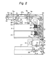
- Fig. 2 is a constructional view of an embodiment of the present invention.
- Bills 22 of one denomination are contained within a first upper bill box 21.
- Bills 24 of another denomination are contained within a second lower bill box 23.
- a bill withdrawing means 25 comprising rollers withdraws the bills 22 one by one from the upper bill box 21.
- the bills 22 are conveyed to a bill pool 28 by conveyor means 27 comprising rollers and belts.
- Bills 24 in the lower bill box 23 are withdrawn from the bill box 23 by a withdrawing means 26 and are also conveyed to the bill pool 28.
- the withdrawing means 25 and 26 and the conveyor means 27 are driven by a motor M 2 (29) through clutch means (not shown).
- a stopper 28a is disposed on the conveyor route 27a above the bill pool 28.
- the stopper 28a can be taken out of the conveyor route 27a, as illustrated by a dashed line, by a motor M 3 (30), to allow an unhindered passage of the bills from the bill pool 28 to a discharge portion 35, along the conveyor route 27a.
- a double feed detector 36 is disposed on the conveyor route defined by the conveyor means 27 so as to detect the simultaneous conveyance of two superimposed bills.
- a transfer gate 31 is disposed on the conveyor route 27a to guide the bills into the rear end portion of the upper bill box 21, through a reject route 33, when an error is detected during the conveyance of the bills.
- the conveyor means along the route 27a from the along bill pool 28 to the discharge portion 35 and/the route 33, are driven by a motor M 4 (32), through clutch means (not shown).
- the bills to be delivered to the user are stopped at a waiting portion 34 for a final confirmation of the amount to be withdrawn by the user, before being discharged from the apparatus through the discharge portion 35.
- a receipt box 37 is disposed below the lower bill box 23.
- the receipt box 37 contains receipts (not shown) having a shape and size similar to the bills 22 and 24. Receipts are taken out of the receipt box 37 one by one by a withdrawing means 38 and conveyed to the lower portions of a printer 41, which prints the prescribed items on the upper surface of the receipt. (on a switchback route The printed receipt is then conveyed,/ irst backward as shown by an arrow A, then forward to the aforementioned conveyor means 27 as shown by an arrow B, so that the printed surface of the receipt is uppermost
- Sensors S 1 to S 13 are disposed on the conveyor routes for receipts and bills.
- the function of each sensor is as follows.
- Sensor S 1 detects the feed motion of r a receipt and controls a clutch associated with the withdrawing means 38.
- Sensor S 2 detects the arrival of the receipt at the printing position below the printer 41.
- Sensor S 3 detects the arrival of the printed receipt at the turning point of the switchback route.
- Sensor S 4 is disposed on the printer side and detects the transfer of the receipt from the printer unit to the bill dispenser unit.
- Sensor S 5 is disposed on the bill dispenser side and detects the transfer of the receipt.
- Sensor S 6 detects the feed motion of bills from the upper bill box 21 by the withdrawing means 25.
- Sensor S 7 detects the feed motion of bills from the lower bill box 23 by the withdrawing means 26.
- Sensors S 8 and S 9 detect bills in the bill pool 28.
- Sensor S 10 detects withdrawal of a receipt and
- Sensor S 11 detects the passage of bills through the reject route.
- Sensor S12 detects the entrance of bills into the rejected bill receiver portion (not shown) of the upper bill box 21.
- Sensor S13 detects bills the presence of at the waitine portion 34.
- the bill dispenser unit of the present invention is further described with reference to Fig. 3.
- the bill box 21 (enclosed by a dash-two-dot line in the Figure) can be withdrawn from the unit together with the withdrawing means 25.
- the withdrawing means 25 comprises a kick roller 25a, a feed roller 25b, and a separate roller 25c.
- the kick roller 25a comprises a kicking projection (not shown) which comes in contact with a bill (not shown) located at the righthand end and feeds the bill downward by the rotation of the roller.
- the feed roller 25b comprises a rubber portion (not shown) on the outer surface thereof for frictional contact with the bill and synchronized with the kick roller 25a so that the rubber portion of the feed roller 25b faces the bill fed by the kick roller 25a.
- the outer surface of the separate roller 25c is made of a high-friction material, to avoid double feed of bills.
- the withdrawing means 25 is connected to the motor M 2 through a clutch CL1. When the bill box 21 is withdrawn from the unit, the withdrawing means 25 is disengaged from the drive means and locked, to prevent rotation of the withdrawing means 25 and thereby avoid accidental withdrawal of the bills contained in the bill box 21.
- the bills are urged forward (rightward) by a pusher 22a connected to a spring 63 disposed under the intermediate floor 21a of the bill box 21.
- a near end switch RSW 11 detects when the pusher 22a is close to indicating that the end position,/ the remaining bills are less than a predetermined quantity.
- Another near end switch RSW 12 even detects when the pusher 22a becomes/closer to the end position.
- Switches SSW 11 to 16 are provided on the bill dispenser side to detect the denomination of the bills contained within the bill box 21. Actuators (not shown) are provided on the bill box 21 at the side corresponding to the switches SSW 11 to 16. One of these actuators is pushed out by a/ operator, to correspond with the denomination of the bills, when the bill boxes 21, 23 are outside the bill dispenser unit, for example, when replenishing the bills, and this actuator will actuate one of switches SSW 11 to 16 when the bill boxes 21, 23 are inserted into the bill dispenser unit.
- a cover 62 for the opening for receiving the rejected bills is provided on the bill box 21.
- the cover 62 is automatically closed and locked when the bill box 21 is withdrawn from the bill dispenser unit by an appropriate locking means (not shown).
- the cover 62 is opened when the bill box 21 is inserted into the bill dispenser unit by an appropriate lock release mechanism provided on the bill dispenser unit.
- the cover 62 is hinged to the bill box 21 in such a manner that it opens upward.
- the double feed detector 36 (Fig. 2) comprises two rollers with a gap between, which gap corresponds to the thickness of a bill. A single bill can pass smoothly through the gap without causing the rollers to rotate. However, if two bills pass through the gap simultaneously, the rollers are forced to rotate by the passing bills, since the frictional force between the bill and the rollers is relatively increased. Sensor means PH 1 and P H2 detect rotation of one of the rollers and thereby detect a double feed of bills. When the sensor means PH1 and PH2 detect a double feed of the bills, the clutch CL3 is cut off to stop the operation of the conveyor means, and also the motor M 2 is stopped to stop any subsequent feed of the bills. The bills received in the bill pool 28 which include the double fed bills are conveyed to the reject box.
- the floor 60 of the bill pool 28 is vertically movable.
- a stopper 61 is disposed on the conveyor route above the bill pool 28.
- the receipt and bills conveyed along the conveyor route abut against the stopper 61 and drop into the bill pool 28.
- the floor 60 moves upward, as illustrated by the dash line, urging the receipt and bills against the conveyor belt.
- the stopper 61 rotates, as illustrated by the dash line, in cooperation with the upward movement of the floor 60, to open the conveyor route passage toward the discharge portion.
- the upper bill box 21 and the lower bill box 23 are exchangeable, and can be used in either position.
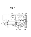
- a receipt printer unit used in an embodiment of the present invention is shown in Fig. 4. Receipts 65 contained in the receipt box 37 are urged forward (rightward) by a pusher 66 which is forced forward by a spring (not shown).
- the receipt box 37 can be withdrawn from the printer unit together with the withdrawing means 38 for withdrawing the receipt from the receipt box 37, as for the billboxes 21, 23 of the bill dispenser unit, for supplementing the receipts.
- a switch S'l detects the installation of the receipt box 37.
- a first and a second near end switches S'll and S'12 detect when the pusher 66 is close to the end position.
- a single receipt is withdrawn from the receipt box 37 by the withdrawing means 38, which has a similar structure to that of the withdrawing means 25 of the bill box 2l,and conveyed to the printing position below the printer 41.
- the receipt can be shifted in the direction perpendicular to the Figure, to change the printing line, by a motor M 5 (64).
- Sensors S'7 to 9 detect the positioning of the receipt to be printed.
- FIG. 5 An outer view of the apparatus for dealing with bills in accordance with the present invention is illustrated in Fig. 5.
- a display window 43 is provided on the front face of the machine body 42 for displaying the operational status of the machine.
- Numeral 44 designates a card inlet.
- Numeral 45 designates a keyboard for inputting the card number and the amount of money to be withdrawn.
- the input information is displayed on a CRT display 46. After the accounting operation is completed, the receipt and the bills are delivered to the user through the discharge portion 47.
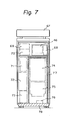
- the bill dispenser unit 74 and the receipt printer unit 75 are, as illustrated in Figs. 7 and 8, enclosed by a safe 77 disposed on a safe floor 78.
- the front side of the safe 77 is constructed as a door, to allow the withdrawal of the bill boxes of the bill dispenser unit 74 and the receipt box of the receipt printer unit 75 from the safe 77.
- An opening 79 is formed on the front upper face of the safe 77 for delivering bills to the user.
- Numeral 76 designates a fan unit.
- Numeral 80 designates a cover for covering the display unit 46 and the keyboard 45.
- a maintenance panel 68 is disposed adjacent to the display unit 46.
- Numeral 70 designates a card reader, and numeral 69 designates a journal printer for printing and recording the result of the accounting operation.
- a local loader 71 houses floppy discs (not shown) which memorize the control program of the machine.
- Numeral 72 designates a controller and numeral 73 designates a power supply.
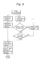
- FIG. 9 A flow chart of the function of an automatic according to the present invention machine for the withdrawal of bills/is briefly illustrated in Fig. 9.
- the central processing unit sends a bill counting order signal and a receipt feeding order signal to the machine in accordance with the information input by the user.
- the bill dispenser unit discharges the ordered amount of bills. If an error, such as double feed of bills or a difference occurs in the amount of bills requested by the accounting order and the detected amount or between the amount detected by the detectors of bill box and that detected by the detectors of the bill pool, the bills are returned to the reject box and more bills are withdrawn from the bill dispenser unit.
- the machine repeats the operation until the correct amount of bills is conveyed to the bill pool. The correct amount of bills and the receipt are then delivered to the user, and the accounting operation is completed.
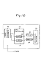
- a block diagram of an embodiment of the present invention is illustrated in Fig. 10.
- a main processor assembly 48 is connected to a central processing unit (not shown) by a cable line.
- An I/O controller 49 controls a mechanical means 53, such as the bill dispenser unit, through various drivers 52.
- the mechanical means 53 is controlled in response to the status of the mechanical means detected by the various sensors 54.
- the I/O controller 49 comprises a processor for controlling the mechanical means 53.
- Another I/O controller is provided for each of the input and output means such as the card reader, the journal printer, and the display.
- a counting order from the main processor assembly 48 is stored in a group of registers 50, which comprises storing regions 21a and 23a corresponding to the bill boxes 21 and 23, respectively.
- a group of counters 51 counts up the bills in accordance with a signal from the sensor for counting bills among the sensors 54.
- the group of counters 51 comprises bill counters 21b and 23b corresponding to the storing regions 21a and 23a of the group of registers 50, respectively.
- the I/O controller 49 forwards count signals to the main processor assembly 48 in response to the output signal from the bill counters 21b and 23b.
- the main processor assembly 48 shown in Fig. 11, comprises a main processor 480, a main memory 482, and a line controller 481.
- the main memory 482 memorizes programs in accordance with which the main processor 480 controls the machine operation.
- the programs are loaded by a memory medium such as a floppy device 485 through a program loader such as a floppy device controller 484.
- a serial interface 483 is disposed for communication between the main processor 480 and the various I/O devices.
- Figs. 12A, 12B, and 12C are block diagrams of the I/O controller of the bill dispenser unit of Fig. 3.
- the controller comprises an interface assembly 491, a processor assembly 490, sensor means 492, 493, and 494, and a driver means 495.
- the interface assembly 491 includes a serial interface and an interface controller.
- the processor assembly 490 includes an I/O processor and interface means for communication with the sensor means 492 to 494 and the drive means 495.
- the outputs of the sensor means 492 comprised of sensors D0, D3 to D10, each sensor comprising a light emitting diode and a light receiving diode, are introduced to a common bus through an amplifier.
- Each output of the photosensor PH1 and PH2 is introduced to a double feed detector through an amplifier.
- Each of photosensors PH5 and PH6 detects whether the shutter of the bill discharge portion of the machine is open or closed and introduces the output signal to the common bus through a Schmitt circuit.
- Microswitches MSW 2 to 4 detect the level of the floor plate of the bill pool and introduce the output signal to the common bus through a Schmitt circuit.
- the sensor means 493 and 494 are arranged for detecting various states of the upper and lower bill boxes 21 and 23, respectively. In the sensor means 493, the output of each of the sensors L11A and L11B, which are disposed at the bill feed portion, is selected through a gate circuit and introduced to the processor.
- Switches RSW 11 and 12 detect the state of the near end of the amount of bills within the bill boxes 21, 23.
- the presence of microswitch MSW 11 detects the/bill boxes 21, 23 when set in the bill dispenser.
- Switches SSW 11 to 16 generate decode signals in accordance with the denomination of the bills contained in the bill boxes 21, 23 set in the bill dispenser.
- the processor selectively picks up the output signals of these switches through the gates and Schmitt circuits.
- the driver means 495 comprises a clutch driver for driving clutches CL l,to 4, a motor driver for driving motors M 2 to M 4 , and a solenoid driver for driving a solenoid which actuates the reject gate 31 (Fig. 2). These drivers are operated by a drive signal from the processor through the common bus.
- Fig. 13 represents a block diagram of the receipt printer unit of Fig. 4.
- the circuit includes an I/O processor 500 connected to the main processor through an interface assembly 501.
- the interface assembly 501 includes an interface controller 501 and a serial interface 511.
- the I/O processor 500 receives output signals from sensors S'l to 12 of the receipt printer unit through an I/O port 502. Also, the I/O processor 500 forwards drive signals to the printer 505 and motors M 1 and M 2 through an I/O port 503.
- the sensor S'l detects when the receipt box is installed within the receipt printer unit.
- the optical sensors S'2 to S'10 are disposed on the receipt conveyor route and detect the conveyance status of the receipts and introduce the output signals to the I/O processor 500.
- the microswitches S'll and S'12 detect the state of the near end of the amount of receipts in the receipt box.
- the printer 505 comprises a seven pin dot printer.
- the head driver 504 actuates each dot pin of the printer in accordance with the character pattern to be printed.
- the motor drivers 506 and 507 drive the motors M1and M 5 in accordance with the order signal from the processor 500.
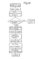
- Fig. 14 is a flow chart of the overall function of the apparatus from the insertion of the user's magnetic card to the withdrawal of the bills together with the receipt by the user.
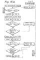
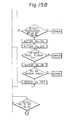
- Figs. 15A, 15B, and 16 are flow charts of the operation of the bill dispenser unit of the present invention.
- the CPU orders the bill dispenser unit to start the accounting operation.
- the function of each sensor is checked, the clutch of the withdrawing means 25 of the upper bill box 21 is actuated so that bills 22 are fed from the bill box 21 one by one, and the sensor S 6 counts the bills. Also, each bill is checked by the double feed detector 36.
- the clutch is turned off and the motor M 2 is stopped so that the subsequent operation of withdrawing bills from the bill box is stopped.
- the motors M 3 and M 4 are driven so that all bills already conveyed to the bill pool are transported to the reject box.
- a new feed operation of bills from the upper bill 21 is started.
- bills 24 of another denomination are withdrawn from the lower bill box 23 and conveyed to and received in the bill pool in the same way as for the bills 22.
- Sensors S 8 and S 9 check the bills received in the bill pool, and the motor M 3 is then driven so that the stopper 28a (Fig.
- the motor M 4 is driven in the reverse direction and the bills and the receipt are returned to the waiting portion 34.
- the apparatus displays a notice informing the user that the money is waiting and has not been withdrawn.
- the function of the receipt printer unit is illustrated in the flow chart of Fig. 17.
- the CPU orders the unit to drive the motor M I ' to feed a receipt.
- the clutch is operated to drive the receipt withdrawing means 38, enabling a single receipt to be withdrawn from the receipt box.
- the sensor S 1 (Fig. 2) detects that the receipt is withdrawn from the receipt box, the clutch is deenergized and the withdrawing means stops functioning.
- the receipt is conveyed to the printing position under the printer 41 by the motor M 1 .
- the sensor S 2 detects when the receipt is at the printing position. Then, the motor M 1 is stopped and the predetermined items are printed on the receipt.
- the motor M l is driven in the reverse direction so that the receipt is conveyed back along the switch back route, as shown by an arrow A, to arrange the receipt in the bill pool so that the printed surface is oriented upward.
- the motor M 1 is stopped to stop the receipt.
- the receipt remains at that point until the predetermined amount of bills are conveyed to the bill pool.
- the CPU orders the printer unit to deliver the receipt.
- the motor M 1 is driven again to convey the receipt in the direction of an arrow B toward the outlet of the printer unit, where the sensor S 4 is disposed. Upon detection of the receipt by the sensor S 4 , the motor M, is stopped.
- the receipt is transferred to the conveyor route of the bill dispensor unit and conveyed to the bill pool by the conveyor means 27.
- the receipt is then placed on the top of the bills stacked on the floor plate of the bill pool and conveyed together with the bills to the discharge portion 35, through which the user withdraws the bills and the receipt from the apparatus.
- each receipt has a shape and a size similar to those of the bills, so that the bill conveyor route can be commonly used as a conveyor route for conveying the receipt, which makes it possible to realize a small automatic machine for dealing with bills.
- the bill conveyor route can be commonly used as a conveyor route for conveying the receipt, which makes it possible to realize a small automatic machine for dealing with bills.
- the rear portion of the bill box of the bill dispenser unit is used as a reject box for receiving rejected bills,and the receipt printer unit is disposed below the bill dispenser unit,make the apparatus small and compact. Further, the user will always be supplied with a receipt since the receipt is delivered to the user together with the bills.
Landscapes
- Physics & Mathematics (AREA)
- General Physics & Mathematics (AREA)
- Pile Receivers (AREA)
- Cash Registers Or Receiving Machines (AREA)
- Financial Or Insurance-Related Operations Such As Payment And Settlement (AREA)
Applications Claiming Priority (2)
| Application Number | Priority Date | Filing Date | Title |
|---|---|---|---|
| JP114181/83 | 1983-06-27 | ||
| JP58114181A JPS607589A (ja) | 1983-06-27 | 1983-06-27 | 紙幣処理装置 |
Publications (3)
| Publication Number | Publication Date |
|---|---|
| EP0130081A2 true EP0130081A2 (fr) | 1985-01-02 |
| EP0130081A3 EP0130081A3 (en) | 1987-08-26 |
| EP0130081B1 EP0130081B1 (fr) | 1990-05-16 |
Family
ID=14631217
Family Applications (1)
| Application Number | Title | Priority Date | Filing Date |
|---|---|---|---|
| EP84304323A Expired - Lifetime EP0130081B1 (fr) | 1983-06-27 | 1984-06-26 | Appareil pour le traitement de documents de valeur |
Country Status (7)
| Country | Link |
|---|---|
| US (1) | US4607155A (fr) |
| EP (1) | EP0130081B1 (fr) |
| JP (1) | JPS607589A (fr) |
| AU (1) | AU550736B2 (fr) |
| CA (1) | CA1229920A (fr) |
| DE (1) | DE3482288D1 (fr) |
| ES (1) | ES8605117A1 (fr) |
Cited By (9)
| Publication number | Priority date | Publication date | Assignee | Title |
|---|---|---|---|---|
| DE3513635A1 (de) * | 1985-04-16 | 1986-10-16 | Nixdorf Computer Ag, 4790 Paderborn | Einrichtung zur annahme, pruefung und aufbewahrung von wertscheinen |
| DE3834062A1 (de) * | 1987-10-08 | 1989-04-20 | Oki Electric Ind Co Ltd | Geldausgabegeraet mit einem mehrfachtresor |
| DE3834061A1 (de) * | 1987-10-12 | 1989-04-20 | Oki Electric Ind Co Ltd | Geldausgabegeraet mit gemeinsamem tansport von banknoten und beleg |
| GB2217086A (en) * | 1988-03-29 | 1989-10-18 | Toshiba Kk | Currency handling system |
| EP0357818A1 (fr) * | 1988-09-07 | 1990-03-14 | International Business Machines Corporation | Méthode pour contrôler deux moyens de transport liés, et machine ainsi contrôlée en particulier machine bancaire personnelle |
| EP0385650A1 (fr) * | 1989-02-28 | 1990-09-05 | De La Rue Systems Limited | Appareillage d'empilement de feuilles |
| EP0774739A3 (fr) * | 1995-11-16 | 1999-05-19 | Ncr International Inc. | Appareil distributeur de monnaie |
| WO1999049421A1 (fr) * | 1998-03-24 | 1999-09-30 | Japan Cash Machine Co., Ltd. | Dispositif muni d'une cassette, destine a contenir et a distribuer des billets de banque |
| US5996993A (en) * | 1996-02-29 | 1999-12-07 | Laurel Bank Machines Co., Ltd. | Bill handling machine |
Families Citing this family (23)
| Publication number | Priority date | Publication date | Assignee | Title |
|---|---|---|---|---|
| US4726474A (en) * | 1984-05-08 | 1988-02-23 | Laurel Bank Machines Co., Ltd. | Circulating-type bill depositing and disbursing machine |
| DE3819909A1 (de) * | 1988-06-11 | 1989-12-21 | Schulte Schlagbaum Ag | Codiereinrichtung fuer magnetkarten |
| GB9014407D0 (en) * | 1990-06-28 | 1990-08-22 | Ncr Co | Document sensing apparatus |
| GB9621501D0 (en) * | 1996-10-15 | 1996-12-04 | Ncr Int Inc | Improved ATM |
| EP1378869B1 (fr) * | 1997-10-06 | 2014-08-06 | Hitachi-Omron Terminal Solutions, Corp. | Dispositif pour traiter des feuilles |
| JP3999476B2 (ja) * | 2001-06-21 | 2007-10-31 | 日立オムロンターミナルソリューションズ株式会社 | 紙幣取扱装置 |
| US6623357B2 (en) * | 2001-06-26 | 2003-09-23 | Igt | Paper token and complementary coupon dispenser |
| US7121460B1 (en) | 2002-07-16 | 2006-10-17 | Diebold Self-Service Systems Division Of Diebold, Incorporated | Automated banking machine component authentication system and method |
| US20040079614A1 (en) * | 2002-10-16 | 2004-04-29 | Orton David R. | Currency and coupon acceptor with coupon printer |
| CA2500881A1 (fr) * | 2005-03-14 | 2006-09-14 | Cashcode Company Inc. | Methode et appareil d'optimisation pour validateur/distributeur de billets de banque |
| US20060219516A1 (en) * | 2005-04-05 | 2006-10-05 | Leon Saltsov | Method and apparatus for optimizing a currency validator/dispenser |
| US8376224B2 (en) | 2006-05-25 | 2013-02-19 | Sean I. Mcghie | Self-service stations for utilizing non-negotiable credits earned from a game of chance |
| US8668146B1 (en) | 2006-05-25 | 2014-03-11 | Sean I. Mcghie | Rewards program with payment artifact permitting conversion/transfer of non-negotiable credits to entity independent funds |
| US8267315B1 (en) | 2006-05-25 | 2012-09-18 | Mcghie Sean I | Exchange of non-negotiable credits for entity independent funds |
| US8162209B2 (en) | 2006-05-25 | 2012-04-24 | Buchheit Brian K | Storefront purchases utilizing non-negotiable credits earned from a game of chance |
| US9704174B1 (en) | 2006-05-25 | 2017-07-11 | Sean I. Mcghie | Conversion of loyalty program points to commerce partner points per terms of a mutual agreement |
| US8684265B1 (en) | 2006-05-25 | 2014-04-01 | Sean I. Mcghie | Rewards program website permitting conversion/transfer of non-negotiable credits to entity independent funds |
| US10062062B1 (en) | 2006-05-25 | 2018-08-28 | Jbshbm, Llc | Automated teller machine (ATM) providing money for loyalty points |
| US7703673B2 (en) | 2006-05-25 | 2010-04-27 | Buchheit Brian K | Web based conversion of non-negotiable credits associated with an entity to entity independent negotiable funds |
| US8342399B1 (en) | 2006-05-25 | 2013-01-01 | Mcghie Sean I | Conversion of credits to funds |
| US8201734B1 (en) | 2006-05-25 | 2012-06-19 | Mcghie Sean I | Conversion of non-negotiable credits associated with an entity into entity independent negotiable funds |
| US8357034B2 (en) | 2007-11-08 | 2013-01-22 | Igt | Gaming system and method providing third party promotions |
| US8506378B2 (en) | 2011-09-21 | 2013-08-13 | Igt | Gaming system, gaming device, and method providing advertising messages to players based on a determination of a positive winning gaming session |
Family Cites Families (8)
| Publication number | Priority date | Publication date | Assignee | Title |
|---|---|---|---|---|
| JPS5522869B2 (fr) * | 1972-12-29 | 1980-06-19 | ||
| JPS6047175B2 (ja) * | 1977-09-07 | 1985-10-19 | 株式会社日立製作所 | 現金自動支払機の一括放出装置 |
| GB2025106B (en) * | 1978-07-10 | 1983-02-09 | Hitachi Ltd | Automatictransaction equipment |
| JPS5586242U (fr) * | 1978-12-06 | 1980-06-14 | ||
| DE3277094D1 (en) * | 1981-03-20 | 1987-10-01 | De La Rue Syst | Cash dispensing apparatus |
| DE3216830C2 (de) * | 1981-05-09 | 1985-11-07 | Laurel Bank Machines Co., Ltd., Tokio/Tokyo | Banknoten-Ein/Ausgabe-Vorrichtung |
| JPS57207991A (en) * | 1981-06-16 | 1982-12-20 | Laurel Bank Machine Co | Automatic paying/receiving machine |
| JPS5812069A (ja) * | 1981-07-15 | 1983-01-24 | Toshiba Corp | 現金支払装置 |
-
1983
- 1983-06-27 JP JP58114181A patent/JPS607589A/ja active Pending
-
1984
- 1984-06-20 CA CA000456997A patent/CA1229920A/fr not_active Expired
- 1984-06-26 EP EP84304323A patent/EP0130081B1/fr not_active Expired - Lifetime
- 1984-06-26 ES ES533721A patent/ES8605117A1/es not_active Expired
- 1984-06-26 DE DE8484304323T patent/DE3482288D1/de not_active Expired - Lifetime
- 1984-06-26 AU AU29892/84A patent/AU550736B2/en not_active Ceased
- 1984-06-27 US US06/625,202 patent/US4607155A/en not_active Expired - Fee Related
Cited By (15)
| Publication number | Priority date | Publication date | Assignee | Title |
|---|---|---|---|---|
| DE3513635A1 (de) * | 1985-04-16 | 1986-10-16 | Nixdorf Computer Ag, 4790 Paderborn | Einrichtung zur annahme, pruefung und aufbewahrung von wertscheinen |
| DE3834062A1 (de) * | 1987-10-08 | 1989-04-20 | Oki Electric Ind Co Ltd | Geldausgabegeraet mit einem mehrfachtresor |
| DE3834062C2 (de) * | 1987-10-08 | 1998-08-13 | Oki Electric Ind Co Ltd | Geldausgabegerät |
| DE3834061A1 (de) * | 1987-10-12 | 1989-04-20 | Oki Electric Ind Co Ltd | Geldausgabegeraet mit gemeinsamem tansport von banknoten und beleg |
| DE3834061C2 (de) * | 1987-10-12 | 1998-04-23 | Oki Electric Ind Co Ltd | Geldausgabegerät |
| GB2217086B (en) * | 1988-03-29 | 1992-04-22 | Toshiba Kk | Currency handling system |
| GB2217086A (en) * | 1988-03-29 | 1989-10-18 | Toshiba Kk | Currency handling system |
| EP0357818A1 (fr) * | 1988-09-07 | 1990-03-14 | International Business Machines Corporation | Méthode pour contrôler deux moyens de transport liés, et machine ainsi contrôlée en particulier machine bancaire personnelle |
| EP0385650A1 (fr) * | 1989-02-28 | 1990-09-05 | De La Rue Systems Limited | Appareillage d'empilement de feuilles |
| EP0774739A3 (fr) * | 1995-11-16 | 1999-05-19 | Ncr International Inc. | Appareil distributeur de monnaie |
| US5996993A (en) * | 1996-02-29 | 1999-12-07 | Laurel Bank Machines Co., Ltd. | Bill handling machine |
| WO1999049421A1 (fr) * | 1998-03-24 | 1999-09-30 | Japan Cash Machine Co., Ltd. | Dispositif muni d'une cassette, destine a contenir et a distribuer des billets de banque |
| US6098837A (en) * | 1998-03-24 | 2000-08-08 | Japan Cash Machine Co., Ltd. | Note hopper/dispenser |
| AU735860B2 (en) * | 1998-03-24 | 2001-07-19 | Japan Cash Machine Co., Ltd. | Note holding and dispensing device with cassette |
| US6325242B1 (en) | 1998-03-24 | 2001-12-04 | Japan Cash Machine Co. Ltd. | Note holding and dispensing device with cassette |
Also Published As
| Publication number | Publication date |
|---|---|
| AU550736B2 (en) | 1986-04-10 |
| ES8605117A1 (es) | 1986-02-16 |
| US4607155A (en) | 1986-08-19 |
| AU2989284A (en) | 1985-01-03 |
| EP0130081A3 (en) | 1987-08-26 |
| DE3482288D1 (de) | 1990-06-21 |
| EP0130081B1 (fr) | 1990-05-16 |
| JPS607589A (ja) | 1985-01-16 |
| CA1229920A (fr) | 1987-12-01 |
| ES533721A0 (es) | 1986-02-16 |
Similar Documents
| Publication | Publication Date | Title |
|---|---|---|
| US4607155A (en) | Apparatus for handling bills | |
| US4558711A (en) | Coin processing apparatus | |
| US4447714A (en) | Dual-purpose automatic apparatus for dispensing and depositing valuable papers and other documents, such as banknotes, cheques, receipts, vouchers etc. | |
| US4739156A (en) | Recycle type transaction apparatus | |
| US4772781A (en) | Sheet transportation control apparatus | |
| US4417137A (en) | Apparatus for dispensing sheet-like elements from a store of such elements, for example banknotes, to one of a plurality of receipt openings accessible to, for example, cashier or customer | |
| US5256862A (en) | Cash managing system | |
| JPH0223912B2 (fr) | ||
| GB2166898A (en) | Automatic bank note transaction apparatus | |
| JP6584630B2 (ja) | 紙葉類取扱装置 | |
| JP2536558Y2 (ja) | 現金入出金装置 | |
| JPH1196440A (ja) | 循環式紙幣入出金機 | |
| JPS6248270B2 (fr) | ||
| JP2614312B2 (ja) | 現金入出金装置 | |
| JPH11195159A (ja) | 紙幣入出金装置 | |
| JP2614330B2 (ja) | 現金入出金装置 | |
| CN210836312U (zh) | 一种现金处理设备 | |
| JPH06162324A (ja) | 紙幣入出金装置 | |
| JP3394319B2 (ja) | 現金自動補充回収システム | |
| JP2773916B2 (ja) | 現金入出金装置 | |
| JPH0239831B2 (fr) | ||
| JP2615197B2 (ja) | 現金入出金装置 | |
| JP3044664B2 (ja) | 紙幣入出金装置 | |
| JPH11259731A (ja) | 自動取引装置およびその制御方法 | |
| JP2763260B2 (ja) | 有価証券収納庫における搬送方向切り換え方法 |
Legal Events
| Date | Code | Title | Description |
|---|---|---|---|
| PUAI | Public reference made under article 153(3) epc to a published international application that has entered the european phase |
Free format text: ORIGINAL CODE: 0009012 |
|
| AK | Designated contracting states |
Designated state(s): DE FR GB |
|
| PUAL | Search report despatched |
Free format text: ORIGINAL CODE: 0009013 |
|
| AK | Designated contracting states |
Kind code of ref document: A3 Designated state(s): DE FR GB |
|
| 17P | Request for examination filed |
Effective date: 19871127 |
|
| 17Q | First examination report despatched |
Effective date: 19880223 |
|
| GRAA | (expected) grant |
Free format text: ORIGINAL CODE: 0009210 |
|
| AK | Designated contracting states |
Kind code of ref document: B1 Designated state(s): DE FR GB |
|
| ET | Fr: translation filed | ||
| REF | Corresponds to: |
Ref document number: 3482288 Country of ref document: DE Date of ref document: 19900621 |
|
| PLBE | No opposition filed within time limit |
Free format text: ORIGINAL CODE: 0009261 |
|
| STAA | Information on the status of an ep patent application or granted ep patent |
Free format text: STATUS: NO OPPOSITION FILED WITHIN TIME LIMIT |
|
| 26N | No opposition filed | ||
| PGFP | Annual fee paid to national office [announced via postgrant information from national office to epo] |
Ref country code: GB Payment date: 19930408 Year of fee payment: 10 |
|
| PGFP | Annual fee paid to national office [announced via postgrant information from national office to epo] |
Ref country code: FR Payment date: 19930629 Year of fee payment: 10 |
|
| PGFP | Annual fee paid to national office [announced via postgrant information from national office to epo] |
Ref country code: DE Payment date: 19930830 Year of fee payment: 10 |
|
| PG25 | Lapsed in a contracting state [announced via postgrant information from national office to epo] |
Ref country code: GB Effective date: 19940626 |
|
| GBPC | Gb: european patent ceased through non-payment of renewal fee |
Effective date: 19940626 |
|
| PG25 | Lapsed in a contracting state [announced via postgrant information from national office to epo] |
Ref country code: FR Effective date: 19950228 |
|
| PG25 | Lapsed in a contracting state [announced via postgrant information from national office to epo] |
Ref country code: DE Effective date: 19950301 |
|
| REG | Reference to a national code |
Ref country code: FR Ref legal event code: ST |