EP0357818A1 - Méthode pour contrôler deux moyens de transport liés, et machine ainsi contrôlée en particulier machine bancaire personnelle - Google Patents
Méthode pour contrôler deux moyens de transport liés, et machine ainsi contrôlée en particulier machine bancaire personnelle Download PDFInfo
- Publication number
- EP0357818A1 EP0357818A1 EP88114602A EP88114602A EP0357818A1 EP 0357818 A1 EP0357818 A1 EP 0357818A1 EP 88114602 A EP88114602 A EP 88114602A EP 88114602 A EP88114602 A EP 88114602A EP 0357818 A1 EP0357818 A1 EP 0357818A1
- Authority
- EP
- European Patent Office
- Prior art keywords
- statement
- time
- transport
- transport means
- cash
- Prior art date
- Legal status (The legal status is an assumption and is not a legal conclusion. Google has not performed a legal analysis and makes no representation as to the accuracy of the status listed.)
- Granted
Links
- 238000000034 method Methods 0.000 title claims abstract description 28
- 238000012544 monitoring process Methods 0.000 claims description 3
- 230000032258 transport Effects 0.000 description 61
- 230000003044 adaptive effect Effects 0.000 description 5
- 230000000903 blocking effect Effects 0.000 description 2
- 230000007257 malfunction Effects 0.000 description 2
- 230000032683 aging Effects 0.000 description 1
- 238000010276 construction Methods 0.000 description 1
- 238000002716 delivery method Methods 0.000 description 1
- 238000004519 manufacturing process Methods 0.000 description 1
- 230000000284 resting effect Effects 0.000 description 1
- 238000011144 upstream manufacturing Methods 0.000 description 1
Images


Classifications
-
- B—PERFORMING OPERATIONS; TRANSPORTING
- B65—CONVEYING; PACKING; STORING; HANDLING THIN OR FILAMENTARY MATERIAL
- B65H—HANDLING THIN OR FILAMENTARY MATERIAL, e.g. SHEETS, WEBS, CABLES
- B65H5/00—Feeding articles separated from piles; Feeding articles to machines
- B65H5/26—Duplicate, alternate, selective, or coacting feeds
-
- G—PHYSICS
- G07—CHECKING-DEVICES
- G07D—HANDLING OF COINS OR VALUABLE PAPERS, e.g. TESTING, SORTING BY DENOMINATIONS, COUNTING, DISPENSING, CHANGING OR DEPOSITING
- G07D11/00—Devices accepting coins; Devices accepting, dispensing, sorting or counting valuable papers
- G07D11/10—Mechanical details
- G07D11/14—Inlet or outlet ports
-
- B—PERFORMING OPERATIONS; TRANSPORTING
- B65—CONVEYING; PACKING; STORING; HANDLING THIN OR FILAMENTARY MATERIAL
- B65H—HANDLING THIN OR FILAMENTARY MATERIAL, e.g. SHEETS, WEBS, CABLES
- B65H2404/00—Parts for transporting or guiding the handled material
- B65H2404/20—Belts
- B65H2404/26—Particular arrangement of belt, or belts
- B65H2404/261—Arrangement of belts, or belt(s) / roller(s) facing each other for forming a transport nip
-
- B—PERFORMING OPERATIONS; TRANSPORTING
- B65—CONVEYING; PACKING; STORING; HANDLING THIN OR FILAMENTARY MATERIAL
- B65H—HANDLING THIN OR FILAMENTARY MATERIAL, e.g. SHEETS, WEBS, CABLES
- B65H2701/00—Handled material; Storage means
- B65H2701/10—Handled articles or webs
- B65H2701/19—Specific article or web
- B65H2701/1912—Banknotes, bills and cheques or the like
Definitions
- the present invention relates to a method for determining and adaptively controlling the optimum moment in time to start a second transport means after a first transport means, both interrelated transport means having different velocities, so that the front edges of both transported items after a certain amount of common way in the transport path, reach a certain end position, whereby said transported items and the paths of their transporting means merge under a certain angle, said angle being preferably up to 90°.
- the invention furthermore relates to a personal banking machine controlled by the inventive method.
- European Patent Specification 0 036 266 B1 describes a banknote dispensing machine with a delivery device for the receipt for the banknotes dispensed.
- banknotes are transported from a first source to a delivery lift.
- the printed receipt, documenting the delivery of the dispensed banknotes is transported from the printer through a second transport path and delivered then to the back of the already stacked bundle of banknotes on the very same lift. If both, banknotes and receipt are collected on the lift, both are transported through an exit slot of the machine. There the consumer can grasp the banknotes together with the printed receipt.
- a cash dispensing machine in which one or more banknote stores and one receipt store are provided in a stack. The lower most or with other words in the transport path the upstream position is provided for the receipt store.
- a receipt is printed and, after the last issued banknote, given into the very same transport path to exit the same gate. A simultaneously exiting of receipt and banknotes at the slot or the exit gate of the banking terminal is not possible with this machine.
- the IBM 4731 Personal Banking Machine provides the possibility to issue banknotes, to issue statements and to issue statements together with banknotes.
- the banknotes are kept in cartridges within a safe and within the safe arranged in the bundle to be issued to the consumer. Only if the bundle contains the correct number of banknotes they are provided on a lift to be issued through a slot within the safe.
- a printer is provided to print the receipt, to print one or more statements, to collect them and to issue them together with the bundle of banknotes simultaneously through one issue gate.
- the consumer grasps the bundle of banknotes together with the statement.
- the bundle of banknotes is transported to the gate by the so-called front drive forming a fist transport means.
- the statement or serveral statements also collected in a bundle are provided by a printer and collected at a statement issuing position. They are exited to the gate by a second transport means. Both transport means coincide at the issue gate in a certain angle of less than 90°.
- a further object of the present invention is to provide a personal banking machine with a control such that banknotes to be issued and stemming from one source and statements stemming from a second source are issued through a common issuing gate simultaneously such that both reach a predetermined end position and no blocking of the gate or jam in the immediate vicinity of the gate or malfunction of the personal banking machine happens.
- the method in accordance with the present invention provides in advantageous manner the optimum point in time for bringing together the front edges of the statement with the banknote so that both on their final way through the gate reach their predetermined end position for optimum functioning of the banking machine.
- the method is adaptively working changes in machine parameters for example a slowing down of motors or other factors do not detrimentally affect the functioning of the machine.
- the adaptive controlling method in accordance with the present invention can preferably be implemented in microcode. This has the advantage that it can be used in different machines having different transport means, without the need to change the microcode. Though the inventive method can be used in a very flexible manner.
- Issue gate 1 is essentially made up by two wall parts 2 and 3 above and below a moveable flap 4. Flap 4 is moveable in direction of double arrow 5 either to the open position as shown in Fig. 1 or to the closed position when Flap 4 is turned to the right in Fig. 1 and closes issue slot 6.
- Issue slot 6 essentially is formed by the right end part of flap 4 and wall part 2 on the left side, seen in Fig. 1, and on the left hand side of wall part 3 on the right side of slot 6.
- a bundle 7 of banknotes in the following only called cash 7.
- statement 8 the statement 8.
- Cash 7 is transported in accordance to arrow 9 by a first transport means 10, called the front drive which is only indicated schematically in Fig. 1.
- Statement 8 is transported by a second transport means 11 in the direction of arrow 12 toward slot 6 of issue gate 1.
- the main directions, indicated by arrows 9 and 12 of the respective first transport means 10 and second transport means 11 are inclined to each other by an angle ⁇ . This angle ⁇ is less than 90°.
- Those transport paths converge within the area of slot 6 of issue gate 1.
- cash 7 touch each other and change in a curved manner their formerly straight direction of movement.
- first transport means 10 there is provided a sensor 13 which is used to sense the end position and the presence of cash 7 in the exit position. Furthermore, in the transport path of second transport means 11, there is provided a sensor 14 for sensing the predetermined end position of statement 8 within exit slot 6 of issue gate 1.
- Fig. 2 shows in addition to the gate area as shown in Fig. 1 further details schematically of the cash issuing first transport means 10 as well as the cash source.
- the cash is kept within a safe 20.
- it is collected as a bundle 21 behind a hook-like member 22 of a lift 23.
- Lift 23 moves the hook-like member 22 which is attached to belt 24 up and down in accordance to double arrow 25.
- hook-like member 22 with bundle 21 is in its upper position of lift 23, the bundle is catched by two transport rollers 26 and furthermore transported to a transport device 27.
- This transport device 27 formed by belts 28 transports the bundle 21 further up and delivers it to first transport means 10.
- First transport means 10 is formed essentially by two belts 29 and 30 which are guided over several rollers and guide the bundle 21 between themselves up to slot 6 of issue gate 1 in accordance with arrow 9.
- FIG. 2 Shown in more detail in Fig. 2 is second transport means 11 that transports statement 8 to slot 6 of issue gate 1. There a statement 8 rests against a hook-like member 15. If second transport means 11 turns clockwise as shown in Fig. 2, then statement 11 resting against hook-like member 15 is transported in direction of arrow 12 toward slot 6 of issue gate 1.
- the adaptive control is characterized by starting the first drive means 10, i.e. front drive and lift 23 together with transport means 27 first, i.e. starting the transport means having the longer transport time first. Then the second transport means 11, the statement exit transport having the shorter transport time, is started after a predetermined delay time DELTA_STATEMENT. The time at which cash 7 has reached its end position and the time at which the statement reaches its respective end position is monitored. Out of the time differences between the times at which cash 7 and statement 8 reach their respective end positions a new predetermined delay time DELTA_STATEMENT is calculated. This new DELTA_STATEMENT is then used as the predetermined delay time for the next combined issue of statement 8 and cash 7. This routine is repeated with every transport action using both transport means.
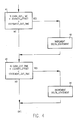
- the program written as microcode uses the following main routines as shown in Fig. 3.
- the program asks if this is the first combined issue for this machine. Is this the case, i.e. that the question is answered with yes, a default value for the DELTA_STATEMENT is fetched for using it for the INITIAL_DELTA_STATEMENT. From block 32 then the program goes to block 33. On the other hand if in the question of block 31 the answer was no, i.e. that it was not the first combined issue for this machine, the program also goes to block 33. In block 33 then the start for issuing cash is initiated. That means that lift 23 and front drive 10 (and also transport means 27) as shown in Fig. 2 are started.
- Block 41 is asking, if the CASH_OUT_TIME plus a DELIVERY_OFFSET is greater than the STATEMENT_OUT_TIME as measured in block 40. If the answer is yes, DELTA_STATEMENT is incremented as shown in block 42. If this is not the case, in block 43 it is asked if the CASH_OUT_TIME plus the DELIVERY_OFFSET is smaller than the STATEMENT_OUT_TIME. If this is the case, then in block 44 a decrement of the DELTA_STATEMENT is performed. If the answer is no in block 43, both come to an end.
- the newly calculated DELTA_STATEMENT is then used in the routine in accordance with Fig. 3, especially as stated in block 33.
- this adaptively corrected DELTA_STATEMENT is used for the start of the system timer in a new issue.
- the time delay after which second transport means 11 for transporting the statement to the gate is thus monitored continuously.
- the internal clock has 50 ms steps to increment the system clock. This time interval of 50 ms is called a time slice.
- DELTA_STATEMENT is the number of time slices the statement issue is started after the start issue cash. This variable is stored in a non-volatile memory.
- CASH_OUT_TIME is the time when the cash stops at the gate in its final end position.
- STATEMENT_OUT_TIME is the time when the statement stops at the gate in its final end position.
- DELIVERY_OFFSET is the time between the cash 7 stops and the statement 8 stops when the optimum meeting point is reached. This variable depends on the statement length's. In a practical example for the statement length's there are provided 101 mm and 106 mm. In this case the same value of 2 time slices is used since the different in length's is only 5 mm.
- INITIAL_DELTA_STATEMENT is a fixed value, that is used in the beginning for the very first cash and statement issuing operation. It is stored and can be replaced later on by the newly calculated DELTA_STATEMENT value.
- the method in accordance with the present invention and also the described personal banking machine including such an adaptive control provides many advantages. So machine specific parameter have not to be determined in the beginning by measuring for each different machine, such as path length of banknotes and velocity of banknotes. Furthermore tolerances in production are considered by the adaptive control and thus an exact mechanical adjustment is not necessary. Also changes in wear and friction caused by aging are considered and thus no readjustment or changing of parts is necessary. A further big advantage is that for the drive of the different transport means cost reducing uncontrolled motors can be used.
Landscapes
- Physics & Mathematics (AREA)
- General Physics & Mathematics (AREA)
- Engineering & Computer Science (AREA)
- Mechanical Engineering (AREA)
- Financial Or Insurance-Related Operations Such As Payment And Settlement (AREA)
- Collation Of Sheets And Webs (AREA)
- Registering Or Overturning Sheets (AREA)
Priority Applications (5)
| Application Number | Priority Date | Filing Date | Title |
|---|---|---|---|
| EP88114602A EP0357818B1 (fr) | 1988-09-07 | 1988-09-07 | Méthode pour contrôler deux moyens de transport liés, et machine ainsi contrôlée en particulier machine bancaire personnelle |
| DE88114602T DE3881690T2 (de) | 1988-09-07 | 1988-09-07 | Verfahren zur Steuerung zweier verbundener Transportmittel und eine auf diese Art gesteuerte Maschine, insbesondere ein persönlicher Bankautomat. |
| JP1155972A JPH0275552A (ja) | 1988-09-07 | 1989-06-20 | 相互に関連した2つの搬送手段を制御する方法 |
| CA000603857A CA1298384C (fr) | 1988-09-07 | 1989-06-23 | Procede de manipulation simultanee de deux materiaux plats; pour guichet automatique, par exemple |
| US07/402,315 US4991829A (en) | 1988-09-07 | 1989-09-05 | Method for controlling two interrelated transport means and machine thus controlled, especially a personal banking machine |
Applications Claiming Priority (1)
| Application Number | Priority Date | Filing Date | Title |
|---|---|---|---|
| EP88114602A EP0357818B1 (fr) | 1988-09-07 | 1988-09-07 | Méthode pour contrôler deux moyens de transport liés, et machine ainsi contrôlée en particulier machine bancaire personnelle |
Publications (2)
| Publication Number | Publication Date |
|---|---|
| EP0357818A1 true EP0357818A1 (fr) | 1990-03-14 |
| EP0357818B1 EP0357818B1 (fr) | 1993-06-09 |
Family
ID=8199279
Family Applications (1)
| Application Number | Title | Priority Date | Filing Date |
|---|---|---|---|
| EP88114602A Expired - Lifetime EP0357818B1 (fr) | 1988-09-07 | 1988-09-07 | Méthode pour contrôler deux moyens de transport liés, et machine ainsi contrôlée en particulier machine bancaire personnelle |
Country Status (5)
| Country | Link |
|---|---|
| US (1) | US4991829A (fr) |
| EP (1) | EP0357818B1 (fr) |
| JP (1) | JPH0275552A (fr) |
| CA (1) | CA1298384C (fr) |
| DE (1) | DE3881690T2 (fr) |
Cited By (1)
| Publication number | Priority date | Publication date | Assignee | Title |
|---|---|---|---|---|
| EP0510798A3 (en) * | 1991-03-12 | 1993-02-24 | Ncr International Inc. | Sheet handling apparatus |
Families Citing this family (6)
| Publication number | Priority date | Publication date | Assignee | Title |
|---|---|---|---|---|
| GB9103104D0 (en) * | 1991-02-14 | 1991-04-03 | Ncr Co | Sheet handling apparatus |
| US5297783A (en) * | 1991-11-12 | 1994-03-29 | Pitney Bowes Inc. | Apparatus and system for handling cut sheets and web forms to form discrete batches |
| US5850075A (en) * | 1996-11-27 | 1998-12-15 | Interbold | Receipt transport and retrieval system for automated banking machine |
| US6656034B2 (en) * | 2001-11-21 | 2003-12-02 | Wms Gaming Inc. | Coin handling device with folding escalator |
| EP2897106B1 (fr) | 2014-01-16 | 2017-06-21 | Wincor Nixdorf International GmbH | Dispositif de manipulation de documents de valeur comprenant un module intermédiaire pouvant être adapté à l'épaisseur de la paroi du coffre-fort |
| CN115188126B (zh) * | 2015-02-18 | 2024-05-28 | 环球娱乐株式会社 | 信息终端 |
Citations (7)
| Publication number | Priority date | Publication date | Assignee | Title |
|---|---|---|---|---|
| US4331328A (en) * | 1980-06-30 | 1982-05-25 | Burroughs Corporation | Controller for a servo driven document feeder |
| US4430606A (en) * | 1980-09-08 | 1984-02-07 | Hitachi, Ltd. | Sheet feeding apparatus |
| EP0130081A2 (fr) * | 1983-06-27 | 1985-01-02 | Fujitsu Limited | Appareil pour le traitement de documents de valeur |
| EP0194139A2 (fr) * | 1985-03-06 | 1986-09-10 | De La Rue Systems Limited | Regroupement de feuilles en une pile |
| EP0244484A1 (fr) * | 1985-10-09 | 1987-11-11 | Mitsubishi Jukogyo Kabushiki Kaisha | Appareil de transfert pour materiaux en plaques |
| GB2191765A (en) * | 1986-06-16 | 1987-12-23 | Sharp Kk | Variable speed sheet refeeding apparatus |
| DE3706810C1 (de) * | 1987-03-03 | 1988-03-31 | Nixdorf Computer Ag | Regelung einer Abzugseinrichtung fuer Blattmaterial |
Family Cites Families (4)
| Publication number | Priority date | Publication date | Assignee | Title |
|---|---|---|---|---|
| FR1577396A (fr) * | 1968-04-19 | 1969-08-08 | ||
| GB2046975A (en) * | 1979-04-11 | 1980-11-19 | De La Rue Syst | Cash dispensing apparatus |
| IT1129433B (it) * | 1980-03-17 | 1986-06-04 | Olivetti & Co Spa | Apparecchiatura di dispensazione di banconote con dispositivo di rilascio della ricevuta delle banconote dispensate |
| GB2141407A (en) * | 1983-06-14 | 1984-12-19 | De La Rue Syst | Cash dispensing |
-
1988
- 1988-09-07 EP EP88114602A patent/EP0357818B1/fr not_active Expired - Lifetime
- 1988-09-07 DE DE88114602T patent/DE3881690T2/de not_active Expired - Fee Related
-
1989
- 1989-06-20 JP JP1155972A patent/JPH0275552A/ja active Granted
- 1989-06-23 CA CA000603857A patent/CA1298384C/fr not_active Expired - Lifetime
- 1989-09-05 US US07/402,315 patent/US4991829A/en not_active Expired - Fee Related
Patent Citations (7)
| Publication number | Priority date | Publication date | Assignee | Title |
|---|---|---|---|---|
| US4331328A (en) * | 1980-06-30 | 1982-05-25 | Burroughs Corporation | Controller for a servo driven document feeder |
| US4430606A (en) * | 1980-09-08 | 1984-02-07 | Hitachi, Ltd. | Sheet feeding apparatus |
| EP0130081A2 (fr) * | 1983-06-27 | 1985-01-02 | Fujitsu Limited | Appareil pour le traitement de documents de valeur |
| EP0194139A2 (fr) * | 1985-03-06 | 1986-09-10 | De La Rue Systems Limited | Regroupement de feuilles en une pile |
| EP0244484A1 (fr) * | 1985-10-09 | 1987-11-11 | Mitsubishi Jukogyo Kabushiki Kaisha | Appareil de transfert pour materiaux en plaques |
| GB2191765A (en) * | 1986-06-16 | 1987-12-23 | Sharp Kk | Variable speed sheet refeeding apparatus |
| DE3706810C1 (de) * | 1987-03-03 | 1988-03-31 | Nixdorf Computer Ag | Regelung einer Abzugseinrichtung fuer Blattmaterial |
Cited By (2)
| Publication number | Priority date | Publication date | Assignee | Title |
|---|---|---|---|---|
| EP0510798A3 (en) * | 1991-03-12 | 1993-02-24 | Ncr International Inc. | Sheet handling apparatus |
| US5330316A (en) * | 1991-03-12 | 1994-07-19 | Ncr Corporation | Sheet handling apparatus and method |
Also Published As
| Publication number | Publication date |
|---|---|
| JPH0561180B2 (fr) | 1993-09-03 |
| EP0357818B1 (fr) | 1993-06-09 |
| JPH0275552A (ja) | 1990-03-15 |
| CA1298384C (fr) | 1992-03-31 |
| US4991829A (en) | 1991-02-12 |
| DE3881690D1 (de) | 1993-07-15 |
| DE3881690T2 (de) | 1993-12-23 |
Similar Documents
| Publication | Publication Date | Title |
|---|---|---|
| US4638993A (en) | Position control for a stacker wheel | |
| EP2104638B1 (fr) | Dispositif de stockage et de délivrance de billets de banque ou d'autres documents flexibles | |
| US9342944B2 (en) | Paper-sheet storing/feeding machine, paper-sheet handling machine and method for storing paper sheets | |
| EP0795842A2 (fr) | Dispositif pour déposer et distribuer des billets de banque | |
| EP2306411B1 (fr) | Dispositif de traitement de feuille de papier et procédé de commande de dispositif de traitement de feuille de papier | |
| EP0357818B1 (fr) | Méthode pour contrôler deux moyens de transport liés, et machine ainsi contrôlée en particulier machine bancaire personnelle | |
| JPS63242838A (ja) | 枚葉物の送り出し装置調整システム | |
| EP0356150A1 (fr) | Manipulateur de feuilles | |
| US4065123A (en) | Apparatus for stacking documents in sequence | |
| US4753431A (en) | Note storing apparatus | |
| US4498665A (en) | Paper sorting/storing apparatus | |
| EP2189952A1 (fr) | Mécanisme de manipulation de feuilles de papier et procédé de manipulation de feuilles de papier | |
| GB2388838A (en) | A note stacker for a currency validator | |
| RU2750042C1 (ru) | Механизм обнаружения незаконных действий, устройство для транспортировки бумажных листов и устройство для обработки бумажных листов | |
| US4877232A (en) | Paper discharge apparatus | |
| AU2008207018B2 (en) | Storing and issuing device for banknotes or other flexible documents | |
| EP3597578B1 (fr) | Système d'alimentation des éléments allongés pour alimenter des éléments allongés à une machine de travail | |
| JPH01197238A (ja) | 紙葉類繰出し機構 | |
| JPH07323931A (ja) | 紙葉類取扱装置の紙葉分離方法 | |
| JP2021187649A (ja) | シート折り装置及び画像形成装置 | |
| CA3259490A1 (fr) | Procédé et système correspondant de stockage de documents souples | |
| JP2001067515A (ja) | 紙幣入金機における紙幣収納機構 | |
| JPS6160549A (ja) | 紙葉類繰出装置 | |
| JPH0289734A (ja) | 紙葉繰出し装置 | |
| JPH0584559B2 (fr) |
Legal Events
| Date | Code | Title | Description |
|---|---|---|---|
| PUAI | Public reference made under article 153(3) epc to a published international application that has entered the european phase |
Free format text: ORIGINAL CODE: 0009012 |
|
| 17P | Request for examination filed |
Effective date: 19890619 |
|
| AK | Designated contracting states |
Kind code of ref document: A1 Designated state(s): DE ES FR GB IT |
|
| 17Q | First examination report despatched |
Effective date: 19920525 |
|
| GRAA | (expected) grant |
Free format text: ORIGINAL CODE: 0009210 |
|
| AK | Designated contracting states |
Kind code of ref document: B1 Designated state(s): DE ES FR GB IT |
|
| PG25 | Lapsed in a contracting state [announced via postgrant information from national office to epo] |
Ref country code: ES Free format text: THE PATENT HAS BEEN ANNULLED BY A DECISION OF A NATIONAL AUTHORITY Effective date: 19930609 |
|
| REF | Corresponds to: |
Ref document number: 3881690 Country of ref document: DE Date of ref document: 19930715 |
|
| ITF | It: translation for a ep patent filed | ||
| ET | Fr: translation filed | ||
| PLBE | No opposition filed within time limit |
Free format text: ORIGINAL CODE: 0009261 |
|
| STAA | Information on the status of an ep patent application or granted ep patent |
Free format text: STATUS: NO OPPOSITION FILED WITHIN TIME LIMIT |
|
| 26N | No opposition filed | ||
| PGFP | Annual fee paid to national office [announced via postgrant information from national office to epo] |
Ref country code: GB Payment date: 19950822 Year of fee payment: 8 |
|
| PGFP | Annual fee paid to national office [announced via postgrant information from national office to epo] |
Ref country code: FR Payment date: 19950911 Year of fee payment: 8 |
|
| PGFP | Annual fee paid to national office [announced via postgrant information from national office to epo] |
Ref country code: DE Payment date: 19950921 Year of fee payment: 8 |
|
| PG25 | Lapsed in a contracting state [announced via postgrant information from national office to epo] |
Ref country code: GB Effective date: 19960907 |
|
| PG25 | Lapsed in a contracting state [announced via postgrant information from national office to epo] |
Ref country code: FR Effective date: 19960930 |
|
| GBPC | Gb: european patent ceased through non-payment of renewal fee |
Effective date: 19960907 |
|
| PG25 | Lapsed in a contracting state [announced via postgrant information from national office to epo] |
Ref country code: DE Effective date: 19970603 |
|
| REG | Reference to a national code |
Ref country code: FR Ref legal event code: ST |
|
| REG | Reference to a national code |
Ref country code: FR Ref legal event code: ST |
|
| PG25 | Lapsed in a contracting state [announced via postgrant information from national office to epo] |
Ref country code: IT Free format text: LAPSE BECAUSE OF NON-PAYMENT OF DUE FEES;WARNING: LAPSES OF ITALIAN PATENTS WITH EFFECTIVE DATE BEFORE 2007 MAY HAVE OCCURRED AT ANY TIME BEFORE 2007. THE CORRECT EFFECTIVE DATE MAY BE DIFFERENT FROM THE ONE RECORDED. Effective date: 20050907 |