EP0130243A1 - Vorrichtung zur Reinigung der Planiertüren und Planierlochrahmen von Verkokungsöfen - Google Patents
Vorrichtung zur Reinigung der Planiertüren und Planierlochrahmen von Verkokungsöfen Download PDFInfo
- Publication number
- EP0130243A1 EP0130243A1 EP83302967A EP83302967A EP0130243A1 EP 0130243 A1 EP0130243 A1 EP 0130243A1 EP 83302967 A EP83302967 A EP 83302967A EP 83302967 A EP83302967 A EP 83302967A EP 0130243 A1 EP0130243 A1 EP 0130243A1
- Authority
- EP
- European Patent Office
- Prior art keywords
- carriage
- drive means
- cleaning apparatus
- coke oven
- oblong frame
- Prior art date
- Legal status (The legal status is an assumption and is not a legal conclusion. Google has not performed a legal analysis and makes no representation as to the accuracy of the status listed.)
- Withdrawn
Links
- 239000000571 coke Substances 0.000 title claims abstract description 20
- 238000004140 cleaning Methods 0.000 title claims abstract description 19
- 238000002347 injection Methods 0.000 claims abstract description 28
- 239000007924 injection Substances 0.000 claims abstract description 28
- XLYOFNOQVPJJNP-UHFFFAOYSA-N water Substances O XLYOFNOQVPJJNP-UHFFFAOYSA-N 0.000 claims abstract description 26
- 230000002441 reversible effect Effects 0.000 claims description 15
- 230000007246 mechanism Effects 0.000 claims description 3
- OKTJSMMVPCPJKN-UHFFFAOYSA-N Carbon Chemical compound [C] OKTJSMMVPCPJKN-UHFFFAOYSA-N 0.000 description 3
- 229910052799 carbon Inorganic materials 0.000 description 3
- 239000003245 coal Substances 0.000 description 1
- 238000010276 construction Methods 0.000 description 1
- 230000000694 effects Effects 0.000 description 1
Images

Classifications
-
- C—CHEMISTRY; METALLURGY
- C10—PETROLEUM, GAS OR COKE INDUSTRIES; TECHNICAL GASES CONTAINING CARBON MONOXIDE; FUELS; LUBRICANTS; PEAT
- C10B—DESTRUCTIVE DISTILLATION OF CARBONACEOUS MATERIALS FOR PRODUCTION OF GAS, COKE, TAR, OR SIMILAR MATERIALS
- C10B43/00—Preventing or removing incrustations
- C10B43/02—Removing incrustations
- C10B43/08—Removing incrustations with liquids
Definitions
- the present invention relates to a cleaning apparatus for a levelling window, a knife edge and the vicinity thereof of a levelling door on a coke oven door.
- a coke oven door is provided on its upper portion with levelling window for levelling the coal charged in the coke oven chamber, and a levelling door having a knife edge is swingably mounted thereon to open and close the levelling window.
- the levelling door is not satisfactorily closed, or the knife edge thereof does not tightly contact the front surface of the levelling window due to carbon and the like stuck on the levelling window, the knife edge and the vicinity thereof, there occurs gas leakage from the inside of the coke oven chamber.
- the object of the present invention is to provide a cleaning apparatus, for cleaning a levelling window, a knife edge and the vicinity thereof of a levelling door on a coke oven door, which is capable of effectively cleaning these parts, by means of a pressurized water injection nozzle, on which the carbon and the like persistently stick.
- the present invention is characterised in that the cleaning apparatus comprises a horizontal underframe mounted on a pusher which runs along the pusher side of a coke oven, an oblong frame movable laterally along the coke oven, a drive means for moving the oblong frame, mounted on the horizontal underframe, a carriage movable toward and away from the coke oven battery and mounted on the oblong frame, a drive means for moving the carriage, a pressurised water injection device having an injection nozzle on its front end and connected to a pressurised water supply pipe, and a lift means mounted on the carriage for moving the pressurised water injection device upwardly and downwardly.
- the cleaning apparatus comprises a horizontal underframe mounted on a pusher which runs along the pusher side of a coke oven, an oblong frame movable laterally along the coke oven, a drive means for moving the oblong frame, mounted on the horizontal underframe, a carriage movable toward and away from the coke oven battery and mounted on the oblong frame,
- the pressurised water injection nozzle can be positioned just in front of the levelling window, the knife edge and the vicinity thereof of the levelling door that has been swung aside from the front face of the levelling window, since the injection nozzle is mounted on the carriage, the carriage can be moved toward and away from the coke oven battery, the oblong frame can be moved along the pusher side, and the pressurised water injection device can be moved up and down.
- these drive means not only the straight portions but also the corner portions where the front surface and the knife edge and its vicinity respectively have right angles can be followed well, thereby allowing these corner portions to be completely cleaned by the pressurised water injection nozzle.
- a horizontal underframe 2 mounted on the upper surface of a coke pusher 1
- a horizontal frame 3 is mounted on the horizontal underframe 2.
- the horizontal frame 3 has, on both sides, see Fig. 2, angular rails 4, 4' for receiving an oblong frame 6 movable to and fro on wheels 5, 5'.
- the horizontal frame 3 is provided with a rotary shaft 7 mounted centrally and extending in longitudinal direction thereof.
- the rotary shaft 7 has a screw-thread (not shown) on its outer surface.
- a reversible motor 8 is mounted on the front of the horizontal frame 3 so as to rotate the rotary shaft 7.
- a screw-engaging member 9 is mounted on the lower surface of a bench plate 10 of the oblong frame 6 and engages through its tapped hole with the rotary shaft 7 so that the oblong frame 6 may be moved forward when the rotary shaft 7 is rotated, for example, clockwise by energising the reversible motor 8, while moved backward when rotated counterclockwise.
- the oblong frame 6 comprises angular iails 11, 11' on which wheels 12, 12' of a carriage 13 ride.
- a reversible motor 14, for rotating a rotary shaft 15, is mounted on the oblong frame 6 as shown in Figs. 2, 3.
- the rotary shaft 15 also has a screw-thread (not shown) on its outer surface.
- a screw-engaging member 16 has a tapped hole which engages the rotary shaft 15 which is coupled to the reversible motor 14.
- the screw-engaging member 16 is arranged such that it causes the carriage 13 to move rightward in Figs. 2, 3 when the rotary shaft 15 is rotated, for example, clockwise
- a support 17 is mounted upright on the carriage 13, and a fitting plate 18 is fixed at both sides thereof on the upper end of the support 17.
- a pair of rotary shafts 20, 20' are set between a gear box 19 of the carriage 13 and bearings 21, 21' provided at both sides on the front face of the fitting plate 18.
- the rotary shafts 20, 20' are also screw-threaded on their outer faces.
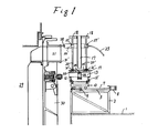
- Gears 22, 22' are respectively fixed on the lower ends of the rotary shafts 20, 20' as shown in Fig. 1.
- a pressurised water supply pipe 25 is connected to a pressurised water injection device 26 which has an injection nozzle 28 on its front end.
- the injection device 26 is supported on a fitting plate 26' as shown in Fig. 2.
- the fitting plate 26' is provided with a pair of screw-engaging members 27, 27' whose tapped holes respectively engage the rotary shafts 20, 20' so that the injection device 26 may be moved down together with the fitting plate 26' when the rotary shafts 20, 20' are rotated in one direction through the gears 22, 22' and 24 by energising the reversible motor 23, while moved up when rotated in the reverse direction.
- the oblong frame 6 is moved forward by energising the reversible motor 8 so that the pressurised water injection nozzle 28 may be positioned just in front of the levelling door frame 31'. Then, while feeding the pressurised water through the supply pipe 25 and injecting from the nozzle 28, the reversible motor 23 for vertical movement and the reversible motor 14 for the lateral movement are respectively energised forwardly or reversely so that. the nozzle 28 may be moved over the front of the levelling door frame 31' to crush and clean off the carbon and the like persistently stuck on the door frame 31'. Then, the nozzle 28 is moved to the front of the levelling door 32 which has been opened so that the knife edge 33 and the vicinity thereof may be cleaned by the pressurised water injected from the nozzle 28 in the same manner as described above.
- the oblong frame 6 is moved back to let the nozzle 28 move away from the levelling door 32, thereby allowing the levelling door 32 to be rotated for closing the levelling window 31. Since the front face of the levelling door frame 31', the knife edge 33 and vicinity thereof of the levelling door 32 are cleaned completely as above, the levelling door 32 can contact closely the surface of the door frame 31' through the knife edge 33, and there can be prevented any gas leakage therethrough.
- the pressurised water injection device 26 Since the pressurised water injection device 26 is supported, in the above embodiment, through the fitting plate 26' by the screw-engaging members 27, 27' which are respectively engaged with the rotary shafts 20, 20' in screw-pair relation, the injection device 26 can be moved up and down while maintaining always its horizontal condition, and further there can be installed the pressurised water injection nozzle 28 of relatively large size on the front of the injection device 260
- the present invention provides such cleaning apparatus that can perform effective cleaning of the door frame, the knife edge and vicinity thereof of the levelling door.
Landscapes
- Chemical & Material Sciences (AREA)
- Engineering & Computer Science (AREA)
- Materials Engineering (AREA)
- Oil, Petroleum & Natural Gas (AREA)
- Organic Chemistry (AREA)
- Cleaning In General (AREA)
- Vehicle Cleaning, Maintenance, Repair, Refitting, And Outriggers (AREA)
- Cleaning By Liquid Or Steam (AREA)
Priority Applications (1)
| Application Number | Priority Date | Filing Date | Title |
|---|---|---|---|
| EP83302967A EP0130243A1 (de) | 1983-05-24 | 1983-05-24 | Vorrichtung zur Reinigung der Planiertüren und Planierlochrahmen von Verkokungsöfen |
Applications Claiming Priority (1)
| Application Number | Priority Date | Filing Date | Title |
|---|---|---|---|
| EP83302967A EP0130243A1 (de) | 1983-05-24 | 1983-05-24 | Vorrichtung zur Reinigung der Planiertüren und Planierlochrahmen von Verkokungsöfen |
Publications (1)
| Publication Number | Publication Date |
|---|---|
| EP0130243A1 true EP0130243A1 (de) | 1985-01-09 |
Family
ID=8191163
Family Applications (1)
| Application Number | Title | Priority Date | Filing Date |
|---|---|---|---|
| EP83302967A Withdrawn EP0130243A1 (de) | 1983-05-24 | 1983-05-24 | Vorrichtung zur Reinigung der Planiertüren und Planierlochrahmen von Verkokungsöfen |
Country Status (1)
| Country | Link |
|---|---|
| EP (1) | EP0130243A1 (de) |
Citations (3)
| Publication number | Priority date | Publication date | Assignee | Title |
|---|---|---|---|---|
| DE2022692A1 (de) * | 1969-05-08 | 1970-11-19 | Uss Eng & Consult | Vorrichtung zur Bearbeitung von Koksofenpfosten |
| EP0017071A1 (de) * | 1979-04-10 | 1980-10-15 | Krupp Koppers GmbH | Einrichtung zum Reinigen der Dichtungsflächen der Planiertüren und Planierlochrahmen von Horizontalkammer-Verkokungsöfen |
| JPS57195788A (en) * | 1981-05-28 | 1982-12-01 | Kouritsu Kikai Kogyo Kk | Means for cleaning levelling hole and small lid of coke oven |
-
1983
- 1983-05-24 EP EP83302967A patent/EP0130243A1/de not_active Withdrawn
Patent Citations (3)
| Publication number | Priority date | Publication date | Assignee | Title |
|---|---|---|---|---|
| DE2022692A1 (de) * | 1969-05-08 | 1970-11-19 | Uss Eng & Consult | Vorrichtung zur Bearbeitung von Koksofenpfosten |
| EP0017071A1 (de) * | 1979-04-10 | 1980-10-15 | Krupp Koppers GmbH | Einrichtung zum Reinigen der Dichtungsflächen der Planiertüren und Planierlochrahmen von Horizontalkammer-Verkokungsöfen |
| JPS57195788A (en) * | 1981-05-28 | 1982-12-01 | Kouritsu Kikai Kogyo Kk | Means for cleaning levelling hole and small lid of coke oven |
Non-Patent Citations (1)
| Title |
|---|
| PATENTS ABSTRACTS OF JAPAN, vol. 7, no. 43 (C-152)[1188], 19th February 1983 & JP - A - 57 195 788 (KOURITSU KIKAI KOGYO K.K.) 01-12-1982 * |
Similar Documents
| Publication | Publication Date | Title |
|---|---|---|
| AU546650B2 (en) | Tape drive door operator | |
| CA1212069A (en) | Device for removing and fitting the charging hole covers of horizontal chamber coke ovens and for cleaning the sealing surfaces | |
| CN204043898U (zh) | 一种阀门寿命测试机 | |
| US9315201B2 (en) | Hopper gate opener | |
| EP0130243A1 (de) | Vorrichtung zur Reinigung der Planiertüren und Planierlochrahmen von Verkokungsöfen | |
| CN109014603A (zh) | 一种便于移动的木材切割机 | |
| CN113682487A (zh) | 一种无人机测绘装置 | |
| CN219364287U (zh) | 道路工程画线设备 | |
| DE2004187B2 (de) | Vorrichtung zum betaetigen des am steigrohr eines verkokungskammerofens angeordneten deckels sowie der verschlussklappe | |
| DE2545265B2 (de) | Füllwagen für Verkokungsöfen | |
| CN216920238U (zh) | 一种手电两用启闭横拉门 | |
| CN214164970U (zh) | 一种用于填补地铁站台缝隙的自动踏板装置及系统 | |
| CN213802834U (zh) | 一种包装生产线用履带式压盖机 | |
| US3526013A (en) | Device for driving sweeper for coke oven door | |
| CN220532507U (zh) | 一种石油管道清洁装置 | |
| CN210324947U (zh) | 一种教学管理用智能宣传板 | |
| CN108868231B (zh) | 一种停车装置 | |
| CN208658344U (zh) | 会议系统用自归位椅子 | |
| CN205471758U (zh) | 一种密封卸料对接装置 | |
| JPH0493175A (ja) | 管内面研掃装置及び曲管内面研掃方法 | |
| CN219932912U (zh) | 一种变速箱油封防护组件 | |
| CN220197261U (zh) | 一种绝缘板表面抛光装置 | |
| CN220481849U (zh) | 一种香菇切丝装置 | |
| CN212044761U (zh) | 辅助监理机器人 | |
| CN217152010U (zh) | 一种用于煤矿的逆向锁止的防风电子风门 |
Legal Events
| Date | Code | Title | Description |
|---|---|---|---|
| PUAI | Public reference made under article 153(3) epc to a published international application that has entered the european phase |
Free format text: ORIGINAL CODE: 0009012 |
|
| AK | Designated contracting states |
Designated state(s): DE FR GB IT NL |
|
| STAA | Information on the status of an ep patent application or granted ep patent |
Free format text: STATUS: THE APPLICATION IS DEEMED TO BE WITHDRAWN |
|
| 18D | Application deemed to be withdrawn |
Effective date: 19850910 |
|
| RIN1 | Information on inventor provided before grant (corrected) |
Inventor name: YOSHITERU, KITANO |