EP0130290A1 - Appareil de navigation - Google Patents
Appareil de navigation Download PDFInfo
- Publication number
- EP0130290A1 EP0130290A1 EP84103886A EP84103886A EP0130290A1 EP 0130290 A1 EP0130290 A1 EP 0130290A1 EP 84103886 A EP84103886 A EP 84103886A EP 84103886 A EP84103886 A EP 84103886A EP 0130290 A1 EP0130290 A1 EP 0130290A1
- Authority
- EP
- European Patent Office
- Prior art keywords
- navigation device
- displayed
- input data
- key
- input unit
- Prior art date
- Legal status (The legal status is an assumption and is not a legal conclusion. Google has not performed a legal analysis and makes no representation as to the accuracy of the status listed.)
- Ceased
Links
Images
Classifications
-
- G—PHYSICS
- G01—MEASURING; TESTING
- G01C—MEASURING DISTANCES, LEVELS OR BEARINGS; SURVEYING; NAVIGATION; GYROSCOPIC INSTRUMENTS; PHOTOGRAMMETRY OR VIDEOGRAMMETRY
- G01C21/00—Navigation; Navigational instruments not provided for in groups G01C1/00 - G01C19/00
- G01C21/26—Navigation; Navigational instruments not provided for in groups G01C1/00 - G01C19/00 specially adapted for navigation in a road network
- G01C21/34—Route searching; Route guidance
- G01C21/36—Input/output arrangements for on-board computers
- G01C21/3626—Details of the output of route guidance instructions
Definitions
- the invention relates to a navigation device for vehicles, in particular for road vehicles, with an input unit for inputting input data via which a specific destination can be entered with its relative destination coordinates relative to the starting point of the vehicle and evaluated to form a destination vector, and with an output device by which the currently valid target vector can be displayed according to amount and direction.
- Such a known navigation device has a keypad as an input unit, which among other things. Buttons for the X and Y coordinates and for the digits 0 to 9.
- the output unit consists of a round instrument with a pointer to show the direction and a digital display to show the amount of the target vector.
- This navigation device is cumbersome to operate due to the large number of buttons and therefore harbors the risk of incorrect entries.
- checking for correct input is not possible, since only the information about the target vector can be displayed according to amount and direction.
- the object of the invention is therefore to provide a navigation device according to the preamble, which provides comprehensive navigation information with simple, safe operation.
- This object is achieved in that the input data input into the input unit can be displayed by the output device. This always gives an overview of the input data.
- the input data can be displayed both during data entry and later on request.
- the display is easy to grasp if the amounts of the input data can be displayed by a digital display.
- the digital display thus fulfills a multiple function.
- the function of a multiple display can be achieved in that the amounts of the target coordinates and / or the declination angle can be displayed as input data.
- the current coordinate values can also be displayed.
- the directions can be used to display the directions of the target coordinates and / or declination angles in multiple functions as input data.
- the current direction of travel can be displayed in another function.
- the input unit has four direction keys assigned to the main cardinal points, by means of which the amount of the respectively assigned coordinate can be entered.
- the usability is further simplified in that the directional keys are arranged like a rose in relation to one another.
- the corresponding compass direction of the direction indicator can be displayed by pressing a direction key. This is possible, for example, by lighting up the respective cardinal direction designation or by displaying the direction.
- the same button can be used in multiple functions both to check the entered data and to change or re-enter data .
- the input unit can have a delete key for deleting the input data.
- a special key element can be dispensed with if the delete key is formed by two direction keys pressed at the same time.
- the input unit can have a declination key, by means of which the declination angle can be set.
- the declination key can be used for two functions, namely to check as well as to re-enter if the declination key can be displayed by the output device when the declination key is pressed and the scroll mode device can be switched on after a certain time.
- the display device can be automatically switched over to the display of the target vector.
- the input unit has a correction key, by means of which the current coordinates can be replaced by the target coordinates, a navigation error that may be present can be eliminated after reaching the target, which is particularly advantageous if the coordinates of several targets are stored in a memory.
- the next destination can be controlled from the correct start dates.
- the input unit can have a toggle button by means of which the directional display can be switched from the target vector to the current direction of travel and vice versa.
- the input unit 1 shown in FIG. 1 has four direction keys 2 arranged like a wind rose, each of which is assigned to a main cardinal point.
- acceleration button 3 in the middle between the direction buttons 2.
- a shift key 4, a destination selection key 5, a correction key 6 and a declination key 7 are arranged one below the other on the right side of the input unit 1.
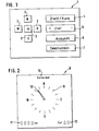
- the output device 8 shown in FIG. 2 has a 360 ° directional display 9 in the form of a wind rose, in which the designations of the main cardinal points can be controlled to illuminate independently of one another. Furthermore, the direction indicator 9 has a pointer 10 that revolves around it.
- a digital display 11 is used to display amounts in the form of numerical values.
- Another two-digit digital destination display 12 serves to indicate the destination of a maximum of ninety-nine storable destinations, the coordinates of which are currently activated to actively control the navigation device.
- the target selection key 5 which is designed as a rocking key and serves to select the target desired and identified by a two-digit number, the target display 12 of which switches over in the scroll mode method when it is actuated.
- the target selection key 5 is released, the target display 12 remains in its currently displayed position. The destination identified by the displayed number is now activated for the navigation device.
- the relative destination coordinates of a certain destination not saved in relation to one certain starting point can be entered into the navigation device.
- the amounts of these target coordinates are determined beforehand, for example using a ruler on a map.
- the acceleration button 3 If you want to accelerate the run-up, press the acceleration button 3 as well. If the desired amount is reached, all you have to do is press the north button. If the amount to be entered in the north direction is to be reduced compared to the amount currently stored, the south button is pressed.
- the coordinate of the desired east value is entered according to the same principle.
- the corresponding designation on the direction indicator 9 lights up and the pointer 10 also adjusts to the corresponding compass direction.
- the amount can be read on the digital display 11 and the associated compass direction on the direction display 9 during the coordinate input.
- the output unit 8 automatically switches back to the target vector, the pointer 10 in the of shows the direction independent of the cardinal direction to the target to be approached and the digital display 11 shows the air line distance to this target.
- the declination angle can be adjusted to influence the direction of the target vector accordingly. This is done by pressing the declination key 7.
- the currently set angle amount appears on the digital display 11. After e.g. 3 seconds this amount begins to change in the scroll mode procedure. When the desired one is reached. Amount only has to be ended by pressing the declaration button 7. The switch to the target vector takes place again automatically after 10 seconds.
- the shift key 4 is pressed. Now the pointer 10 points in the cardinal direction in which the vehicle is currently traveling. At the same time, the lettering 13 "course angle" lights up. To switch back to the target vector, the shift key 4 must now be pressed a second time.
- an input unit 1 which has only a few keys and with an output device 8 which functions in a multiple function and is easy to grasp, it is possible to obtain optimal navigation information.
- the input unit 1 can also be equipped with any other type of input element instead of keys.
- the keys can also be equipped with information such as barcodes that is optically readable with a light pen.
- the direction indicator 9 which shows the corresponding compass direction when a direction button 2 is actuated can e.g. Pressing the north button also shows south if the values of the Y coordinates are not plus values but minus values.
Landscapes
- Engineering & Computer Science (AREA)
- Radar, Positioning & Navigation (AREA)
- Remote Sensing (AREA)
- Automation & Control Theory (AREA)
- Physics & Mathematics (AREA)
- General Physics & Mathematics (AREA)
- Navigation (AREA)
- Control Of Position, Course, Altitude, Or Attitude Of Moving Bodies (AREA)
- Control Of Driving Devices And Active Controlling Of Vehicle (AREA)
- Instrument Panels (AREA)
Applications Claiming Priority (2)
| Application Number | Priority Date | Filing Date | Title |
|---|---|---|---|
| DE19833319207 DE3319207A1 (de) | 1983-05-27 | 1983-05-27 | Navigationseinrichtung |
| DE3319207 | 1983-05-27 |
Publications (1)
| Publication Number | Publication Date |
|---|---|
| EP0130290A1 true EP0130290A1 (fr) | 1985-01-09 |
Family
ID=6199989
Family Applications (1)
| Application Number | Title | Priority Date | Filing Date |
|---|---|---|---|
| EP84103886A Ceased EP0130290A1 (fr) | 1983-05-27 | 1984-04-07 | Appareil de navigation |
Country Status (4)
| Country | Link |
|---|---|
| EP (1) | EP0130290A1 (fr) |
| JP (1) | JPS6051913A (fr) |
| AU (1) | AU559462B2 (fr) |
| DE (1) | DE3319207A1 (fr) |
Cited By (1)
| Publication number | Priority date | Publication date | Assignee | Title |
|---|---|---|---|---|
| FR2660428A1 (fr) * | 1990-04-03 | 1991-10-04 | Sagem | Systeme d'aide a la navigation pour vehicule terrestre. |
Families Citing this family (7)
| Publication number | Priority date | Publication date | Assignee | Title |
|---|---|---|---|---|
| DE3468762D1 (en) * | 1983-05-27 | 1988-02-18 | Vdo Schindling | Information input arrangement |
| DE3519277A1 (de) * | 1985-05-30 | 1986-12-04 | Robert Bosch Gmbh, 7000 Stuttgart | Navigationsverfahren fuer fahrzeuge |
| EP0282639A3 (fr) * | 1987-03-14 | 1989-08-30 | Franz Kirchberger | Procédé et dispositif de commande de machines agricoles en fonction de leur position sur une surface à cultiver |
| JPH03127214U (fr) * | 1990-04-05 | 1991-12-20 | ||
| JPH04283788A (ja) * | 1991-03-13 | 1992-10-08 | Pioneer Electron Corp | 車両の経路誘導装置 |
| EP0781978B1 (fr) * | 1992-02-18 | 2000-02-02 | Pioneer Electronic Corporation | Dispositif de navigation avec fonction d'affichage de position améliorée |
| DE19754169B4 (de) * | 1997-12-06 | 2008-11-13 | Volkswagen Ag | Vorrichtung zum Starten einer in einem Fahrzeug eingebauten Navigationseinrichtung und Steuerungsverfahren dafür |
Citations (5)
| Publication number | Priority date | Publication date | Assignee | Title |
|---|---|---|---|---|
| FR2448202A1 (fr) * | 1979-01-31 | 1980-08-29 | Fleischmann Pascal | Appareil indicateur d'itineraires |
| DE2910386A1 (de) * | 1979-03-16 | 1980-09-25 | Teldix Gmbh | Navigationsanlage |
| EP0027232A2 (fr) * | 1979-10-11 | 1981-04-22 | Siemens Aktiengesellschaft | Navigateur autonome pour véhicules routiers |
| DE3006141A1 (de) * | 1980-02-19 | 1981-10-08 | Manfred 8501 Siegelsdorf Rennings | Verfahren und vorrichtung zur wegweisung eines verkehrsteilnehmers, insbesondere eines kraftfahrzeuges |
| DE3222285A1 (de) * | 1981-06-15 | 1982-12-30 | Toyota Jidosha Kogyo K.K., Toyota, Aichi | Reisestandort-sichtanzeigegeraet |
-
1983
- 1983-05-27 DE DE19833319207 patent/DE3319207A1/de not_active Withdrawn
-
1984
- 1984-04-07 EP EP84103886A patent/EP0130290A1/fr not_active Ceased
- 1984-05-22 AU AU28489/84A patent/AU559462B2/en not_active Ceased
- 1984-05-25 JP JP59104898A patent/JPS6051913A/ja active Pending
Patent Citations (5)
| Publication number | Priority date | Publication date | Assignee | Title |
|---|---|---|---|---|
| FR2448202A1 (fr) * | 1979-01-31 | 1980-08-29 | Fleischmann Pascal | Appareil indicateur d'itineraires |
| DE2910386A1 (de) * | 1979-03-16 | 1980-09-25 | Teldix Gmbh | Navigationsanlage |
| EP0027232A2 (fr) * | 1979-10-11 | 1981-04-22 | Siemens Aktiengesellschaft | Navigateur autonome pour véhicules routiers |
| DE3006141A1 (de) * | 1980-02-19 | 1981-10-08 | Manfred 8501 Siegelsdorf Rennings | Verfahren und vorrichtung zur wegweisung eines verkehrsteilnehmers, insbesondere eines kraftfahrzeuges |
| DE3222285A1 (de) * | 1981-06-15 | 1982-12-30 | Toyota Jidosha Kogyo K.K., Toyota, Aichi | Reisestandort-sichtanzeigegeraet |
Cited By (1)
| Publication number | Priority date | Publication date | Assignee | Title |
|---|---|---|---|---|
| FR2660428A1 (fr) * | 1990-04-03 | 1991-10-04 | Sagem | Systeme d'aide a la navigation pour vehicule terrestre. |
Also Published As
| Publication number | Publication date |
|---|---|
| DE3319207A1 (de) | 1984-11-29 |
| AU2848984A (en) | 1984-11-29 |
| AU559462B2 (en) | 1987-03-12 |
| JPS6051913A (ja) | 1985-03-23 |
Similar Documents
| Publication | Publication Date | Title |
|---|---|---|
| DE3222285C2 (de) | Positionsanzeigeeinrichtung für ein Fahrzeug | |
| DE69215182T2 (de) | Navigationsvorrichtung | |
| DE2551771C2 (de) | Vorrichtung zum Anzeigen der geographischen Position eines gesteuerten Fahrzeugs | |
| DE3515471C2 (fr) | ||
| EP0262122B1 (fr) | Systeme de navigation pour vehicules | |
| DE3645100C2 (de) | Navigationssystem fuer kraftfahrzeuge | |
| DE69025192T2 (de) | Navigationsapparat und -methode | |
| DE3515181A1 (de) | Navigationssystem fuer selbstgetriebene fahrzeuge | |
| DE3719702A1 (de) | Verfahren und einrichtung zur navigation | |
| DE4118603C2 (de) | Navigationsgerät für Fahrzeuge | |
| DE3509708A1 (de) | Navigationssystem fuer selbstgetriebene fahrzeuge | |
| DE3317911C2 (de) | Anzeigeeinrichtung zur visuellen Anzeige des augenblicklichen Ortes eines Fahrzeuges | |
| DE3429882A1 (de) | Fahrkursleitgeraet | |
| EP0110171A2 (fr) | Dispositif de repérage de la position d'un véhicule | |
| EP0130290A1 (fr) | Appareil de navigation | |
| DE3613422C2 (fr) | ||
| DE10218340A1 (de) | Navigationssystem und Verfahren zur Routenbestimmung | |
| EP0044930A1 (fr) | Dispositif de traitement du texte ayant un dispositif indicateur | |
| EP0103847A1 (fr) | Dispositif d'aide à la navigation pour véhicules | |
| DE3319208A1 (de) | Navigationseinrichtung | |
| EP1290409A1 (fr) | Dispositif servant a entrer des noms dans un systeme de navigation, ainsi que systeme de navigation pour vehicules automobiles | |
| DE3434896C2 (fr) | ||
| DE4345274C5 (de) | Navigationseinrichtung | |
| DE19544382C2 (de) | Verfahren und Zielführungseinheit zur sicheren Zielführung eines Fahrzeugs | |
| DE1423094A1 (de) | Geraet zur Anzeige des Standortes von Fahrzeugen in der Karte |
Legal Events
| Date | Code | Title | Description |
|---|---|---|---|
| PUAI | Public reference made under article 153(3) epc to a published international application that has entered the european phase |
Free format text: ORIGINAL CODE: 0009012 |
|
| 17P | Request for examination filed |
Effective date: 19841018 |
|
| AK | Designated contracting states |
Designated state(s): DE FR GB IT |
|
| 17Q | First examination report despatched |
Effective date: 19860224 |
|
| D17Q | First examination report despatched (deleted) | ||
| STAA | Information on the status of an ep patent application or granted ep patent |
Free format text: STATUS: THE APPLICATION HAS BEEN REFUSED |
|
| 18R | Application refused |
Effective date: 19870213 |
|
| RIN1 | Information on inventor provided before grant (corrected) |
Inventor name: ANGERMUELLER, HELMUT, DR. Inventor name: HAHLGANSS, GUENTER Inventor name: PRESSE, JOACHIM |