EP0130574A1 - Dispositif pour compenser la dérive de la ligne de base d'une colonne chromatographique - Google Patents
Dispositif pour compenser la dérive de la ligne de base d'une colonne chromatographique Download PDFInfo
- Publication number
- EP0130574A1 EP0130574A1 EP84107477A EP84107477A EP0130574A1 EP 0130574 A1 EP0130574 A1 EP 0130574A1 EP 84107477 A EP84107477 A EP 84107477A EP 84107477 A EP84107477 A EP 84107477A EP 0130574 A1 EP0130574 A1 EP 0130574A1
- Authority
- EP
- European Patent Office
- Prior art keywords
- temperature
- baseline
- separation column
- program
- signal
- Prior art date
- Legal status (The legal status is an assumption and is not a legal conclusion. Google has not performed a legal analysis and makes no representation as to the accuracy of the status listed.)
- Granted
Links
- 238000013375 chromatographic separation Methods 0.000 claims abstract description 7
- 238000005259 measurement Methods 0.000 claims description 16
- 230000001419 dependent effect Effects 0.000 claims description 2
- 238000012360 testing method Methods 0.000 abstract description 10
- 238000000926 separation method Methods 0.000 description 36
- 230000006870 function Effects 0.000 description 21
- 239000000203 mixture Substances 0.000 description 8
- 230000005526 G1 to G0 transition Effects 0.000 description 4
- 239000007788 liquid Substances 0.000 description 4
- 238000004458 analytical method Methods 0.000 description 2
- 238000004364 calculation method Methods 0.000 description 2
- 238000004817 gas chromatography Methods 0.000 description 2
- 238000012545 processing Methods 0.000 description 2
- 239000000126 substance Substances 0.000 description 2
- 101100272203 Arabidopsis thaliana BASL gene Proteins 0.000 description 1
- 238000013459 approach Methods 0.000 description 1
- 230000000740 bleeding effect Effects 0.000 description 1
- 239000012159 carrier gas Substances 0.000 description 1
- 238000004587 chromatography analysis Methods 0.000 description 1
- 239000000470 constituent Substances 0.000 description 1
- 238000013461 design Methods 0.000 description 1
- 238000010586 diagram Methods 0.000 description 1
- 230000000694 effects Effects 0.000 description 1
- 239000007789 gas Substances 0.000 description 1
- 238000010438 heat treatment Methods 0.000 description 1
- 238000012804 iterative process Methods 0.000 description 1
- 238000012886 linear function Methods 0.000 description 1
- 238000004811 liquid chromatography Methods 0.000 description 1
- 238000000034 method Methods 0.000 description 1
- 230000006641 stabilisation Effects 0.000 description 1
- 238000011105 stabilization Methods 0.000 description 1
- 230000036962 time dependent Effects 0.000 description 1
- 238000012546 transfer Methods 0.000 description 1
Images


Classifications
-
- G—PHYSICS
- G01—MEASURING; TESTING
- G01N—INVESTIGATING OR ANALYSING MATERIALS BY DETERMINING THEIR CHEMICAL OR PHYSICAL PROPERTIES
- G01N30/00—Investigating or analysing materials by separation into components using adsorption, absorption or similar phenomena or using ion-exchange, e.g. chromatography or field flow fractionation
- G01N30/02—Column chromatography
- G01N30/86—Signal analysis
- G01N30/8624—Detection of slopes or peaks; baseline correction
-
- G—PHYSICS
- G01—MEASURING; TESTING
- G01N—INVESTIGATING OR ANALYSING MATERIALS BY DETERMINING THEIR CHEMICAL OR PHYSICAL PROPERTIES
- G01N30/00—Investigating or analysing materials by separation into components using adsorption, absorption or similar phenomena or using ion-exchange, e.g. chromatography or field flow fractionation
- G01N30/02—Column chromatography
- G01N30/62—Detectors specially adapted therefor
- G01N2030/626—Detectors specially adapted therefor calibration, baseline
-
- G—PHYSICS
- G01—MEASURING; TESTING
- G01N—INVESTIGATING OR ANALYSING MATERIALS BY DETERMINING THEIR CHEMICAL OR PHYSICAL PROPERTIES
- G01N30/00—Investigating or analysing materials by separation into components using adsorption, absorption or similar phenomena or using ion-exchange, e.g. chromatography or field flow fractionation
- G01N30/02—Column chromatography
- G01N30/86—Signal analysis
- G01N30/8624—Detection of slopes or peaks; baseline correction
- G01N30/8641—Baseline
Definitions
- the invention relates to a device for compensating for the baseline drift of a chromatographic separation column during a temperature and / or flow program.
- a separation column contains a separation substance that interacts more or less strongly with the individual components of a mixture to be examined.
- the separating substance is a liquid as a stationary phase, in which the constituents of the mixture to be examined are more or less easily soluble.
- a carrier medium carrier gas or carrier liquid
- That too investigating mixture is placed on the entrance of the separation column and transported from the carrier medium through the separation column.
- a component that is easily soluble in a liquid stationary phase for example, migrates more slowly through the separation column than a component that is less soluble or more volatile in this stationary phase.
- a sample given as a "packet" at the entrance to the separation column therefore dissolves on its way through the separation column into the individual components of the mixture, which migrate more or less quickly through the separation column and appear in succession at the exit of the separation column.
- a detector is arranged there, which responds to exiting components of the sample and delivers corresponding signals.
- the chronological course of the detector signal, the chromatogram shows a sequence of bands or peaks, each of which corresponds to a component of the mixture.
- the detector also provides a signal when no sample is placed on the separation column.
- This signal is constant at constant temperature and constant flow velocity. In a recording of the chromatogram, this signal gives a straight, horizontal baseline to which the peaks can be related. In a temperature or flow rate program, however, the "baseline signal” changes with a change in temperature or flow rate. This change in the baseline signal must be taken into account when evaluating the chromatogram.
- the detector signal obtained from the output of the active separation column is corrected by the detector signal from the output of the reference separation column.
- Such an arrangement is complex. Two identically designed separating columns with detectors must be provided and placed in an appropriately sized oven. A prerequisite for perfect baseline compensation is still the exactly matching design of the separation column and exactly matching, programmed operating conditions. This requirement can lead to measurement errors.
- the invention has for its object to provide a device for compensating the baseline drist of a chromatographic separation column during a temperature and / or flow program, which is simplified compared to the prior art.
- the invention is further based on the object of providing a device for compensating for the baseline drift of a chromatographic separation column during a temperature and / or flow program: in which measurement errors which occur in the prior art are avoided.
- the invention has for its special object to provide a device for compensating the baseline drift of a chromatographic separation column during a temperature and / or flow program, which requires only a single separation column.
- a temperature program is then run through with the one separation column, from which the parameters of the said function are determined. These parameters are then specified in the function generator means.
- the function generator means then deliver the respective base line signals in a temperature and / or flow rate programmed measurement run with a sample placed on the separation column. The measurement signals are corrected with these baseline signals.
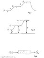
- 10 denotes a separation column which is heated up according to a temperature program.
- the temperature program is entered on an operator panel. It is characterized by three temperature levels ⁇ 1 , & 2 and ⁇ 3 , which occur during the time intervals t1, t 2 and t 3 , respectively, and the temperature rise rates R 1 and R 2 , with which the temperature between the temperature levels ⁇ 1 and ⁇ 2 and ⁇ 2, respectively . ⁇ 2 and ⁇ 3 increases.
- a detector 12 At the outlet of the separating column 10 there is a detector 12 which responds to the components of a mixture which is applied as a sample and which emerges from the separating column 10.
- the sample is placed on the entrance of the separation column 10 and transported through the separation column 10 by a carrier medium in the manner described at the beginning and is broken down into its components.
- the detector 12 delivers a baseline signal even in the absence of sample components, as explained above.
- the signal of the detector 12 is amplified by an amplifier 14 and digitized by means of an analog-digital converter 16.
- the signal processing takes place digitally by means of a suitably programmed microprocessor. However, signal processing can also be carried out analogously.
- a test run is first carried out in which no sample is placed on the separation column 10.
- a test run circuit 18 is effective, which is symbolized by the fact that the switch 20 in FIG. 1 is in its right switch position.
- the test run circuit 18 specifies a temperature program for the separation column 10, as defined by the temperature levels ⁇ 1 , ⁇ 2 and ⁇ 3 , the time intervals t 11 t 2 , t 3 and the rise rates R 1 , R 2 and shown in FIG. 2 is, and at the same time applies the signal "zero" via switch 20 to difference-forming means 22, to which the output of the analog-to-digital converter 16 is also fed.
- the difference-forming means thus supply the uncorrected detector signal, which has the course shown in FIG. 3.
- This detector signal is sent to a computing circuit 24, to which the temperature levels ⁇ 1 , ⁇ 2 and ⁇ 3 , the time intervals t 1 , t 2 , t 3 and the rise rates R 1 , R 2 are also supplied.
- the arithmetic circuit 24 calculates the parameters of the function representing the baseline from this in a manner yet to be described. These parameters are entered in function generator means 26.
- the function generator means 20 are not effective during the test run described, as indicated by the switch 20 in FIG. 1.
- the function generator means In a subsequent measurement run in which a sample is placed on the separation column 10, the function generator means likewise receive temperature levels ⁇ 1 , ⁇ 2 , ⁇ 3 , time intervals t 1 , t 2 , t 3 and rise rates R 1 , R 2 of a temperature program as input signals (eg FIG. 6) and deliver a signal at an output 28 according to the function representing the baseline. This signal is of the same type as the measurement signal.
- the function generator means also supply a signal in digital form. This signal from the function generator means 26 is subtracted from the measurement signal by the difference-forming means 22.
- the difference-forming means 22 represent "means for correcting the measurement signal with the baseline signal".
- the parameters of the function representing the baseline are calculated in the calculation circuit 24 in the following way.
- This basic equation contains three constants, the values of which are unknown and must therefore be determined experimentally. This is done in that the separation column is operated at different temperatures according to the temperature program shown in FIG. 2.
- Each isothermal time interval during a test run corresponds to a specific background signal that can be easily determined. These are underground signals.
- the result is a set of three equations with three unknowns. Nonetheless, it is not possible to explicitly calculate these three unknown constants.
- the constants must be determined using an iteration method.
- the constants b, a and I o are derived from the following equations: -
- Equations (6) and (7) apply to the first temperature rise from the first isothermal time interval at temperature ⁇ 1 .
- the subsequent temperature rise from the second isothermal time interval at temperature ⁇ 2 at the rate R 2 of the program rise is described by
- the time constant must again be calculated using an iterative process. That can be done according to the formula happen or from the second temperature rise according to the formula
- equation (11) Substituting equation (11) into equation (1) yields a function that describes the true behavior of the baseline during stabilization at a new temperature level:
- the program is listed in the Basic programming language, which is used to calculate the special column data a, b, I and ⁇ and to record the base line point by point (corresponding to the calculation circuit 24 in FIG. 1).
- the program BASL 2 which is also appended, lists the program which is used to calculate the baseline from the special column data and the parameters of the temperature program (corresponding to function generator means 26 in FIG. 1).
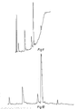
- FIGS. 6 to 10 Results achieved with a device of the type described are shown in FIGS. 6 to 10 shown.
- 6 to 8 show the good agreement between the measured and calculated baseline for a "test run" without a sample.
- 9 and 10 show the compensation of the baseline drift by means of a baseline signal calculated in the manner described.
- the described example describes the compensation of a baseline drift that is caused by a temperature program.
- Baseline drift caused by a flow rate program can also be compensated in a similar manner.
Landscapes
- Physics & Mathematics (AREA)
- Health & Medical Sciences (AREA)
- Life Sciences & Earth Sciences (AREA)
- Chemical & Material Sciences (AREA)
- Analytical Chemistry (AREA)
- Biochemistry (AREA)
- General Health & Medical Sciences (AREA)
- General Physics & Mathematics (AREA)
- Immunology (AREA)
- Pathology (AREA)
- Treatment Of Liquids With Adsorbents In General (AREA)
- Investigating Or Analyzing Materials Using Thermal Means (AREA)
- Amplifiers (AREA)
- Aerials With Secondary Devices (AREA)
- Variable-Direction Aerials And Aerial Arrays (AREA)
Applications Claiming Priority (2)
| Application Number | Priority Date | Filing Date | Title |
|---|---|---|---|
| DE3323744 | 1983-07-01 | ||
| DE19833323744 DE3323744A1 (de) | 1983-07-01 | 1983-07-01 | Einrichtung zur kompensation der basisliniendrift einer chromatographischen trennsaeule |
Publications (2)
| Publication Number | Publication Date |
|---|---|
| EP0130574A1 true EP0130574A1 (fr) | 1985-01-09 |
| EP0130574B1 EP0130574B1 (fr) | 1987-09-30 |
Family
ID=6202894
Family Applications (1)
| Application Number | Title | Priority Date | Filing Date |
|---|---|---|---|
| EP84107477A Expired EP0130574B1 (fr) | 1983-07-01 | 1984-06-28 | Dispositif pour compenser la dérive de la ligne de base d'une colonne chromatographique |
Country Status (4)
| Country | Link |
|---|---|
| US (1) | US4927532A (fr) |
| EP (1) | EP0130574B1 (fr) |
| JP (1) | JPS6085367A (fr) |
| DE (2) | DE3323744A1 (fr) |
Cited By (4)
| Publication number | Priority date | Publication date | Assignee | Title |
|---|---|---|---|---|
| US4927532A (en) * | 1983-07-01 | 1990-05-22 | The Perkin-Elmer Corporation | Device for the compensation of the baseline drift of a chromatographic separating column |
| EP0354618A3 (fr) * | 1988-08-10 | 1991-05-15 | Philips Patentverwaltung GmbH | Appareil d'analyse chimique |
| GB2297045A (en) * | 1995-01-23 | 1996-07-24 | Hewlett Packard Co | Sensor drift correction in a gas chromatograph |
| CN109541100A (zh) * | 2018-12-13 | 2019-03-29 | 安徽皖仪科技股份有限公司 | 多通道波长的信号漂移处理方法、装置及多通道检测器 |
Families Citing this family (16)
| Publication number | Priority date | Publication date | Assignee | Title |
|---|---|---|---|---|
| US5618907A (en) | 1985-04-23 | 1997-04-08 | The Boeing Company | Thallium catalyzed multidimensional ester oligomers |
| EP0359320A3 (fr) * | 1988-09-14 | 1991-10-23 | Philips Electronics Uk Limited | Chromatographe |
| US5203992A (en) * | 1989-06-23 | 1993-04-20 | Hewlett-Packard Company | Apparatus for optimizing the liquid chromatographic separation of a sample |
| JP2800509B2 (ja) * | 1990-11-30 | 1998-09-21 | 株式会社日立製作所 | 液体クロマトグラフ装置 |
| US5347474A (en) * | 1991-09-19 | 1994-09-13 | Gaztech Corporation | Self-calibration of an NDIR gas sensor |
| WO1996004607A1 (fr) * | 1991-09-19 | 1996-02-15 | Telaire Systems, Inc. | Auto-etalonnage d'un capteur de gaz infrarouge non dispersif |
| DE69323645T2 (de) * | 1992-05-18 | 1999-09-09 | Hewlett-Packard Co. | Verfahren zur Berechnung der Betriebsparameter eines Gaschromatografens |
| US5670054A (en) * | 1996-04-04 | 1997-09-23 | Warner Lambert Company | Method and system for identification, purification, and quantitation of reaction components |
| US5987959A (en) * | 1996-10-10 | 1999-11-23 | Hewlett-Packard Company | Automated retention time locking |
| US5827946A (en) * | 1997-04-30 | 1998-10-27 | Hewlett-Packard Company | Method for sample identification using a locked retention time database |
| US5939612A (en) * | 1998-04-28 | 1999-08-17 | Hewlett-Packard Company | Retention time-locked spectral database for target analyte analysis |
| SE9801949D0 (sv) * | 1998-06-02 | 1998-06-02 | Astra Ab | Process control |
| US6036747A (en) * | 1998-07-24 | 2000-03-14 | Hewlett-Packard Company | Column specific parameters for retention time locking in chromatography |
| US6408684B1 (en) * | 1999-03-31 | 2002-06-25 | Shimadzu Corporation | Detection device for apparatus for analysis |
| EP1275958A1 (fr) * | 2001-07-05 | 2003-01-15 | Agilent Technologies, Inc. (a Delaware corporation) | Procèdè pour la supression d'instabilités de la ligne de base en chromatographie en phase liquide et dispositif de chromatographie en phase liquide |
| WO2014091888A1 (fr) * | 2012-12-10 | 2014-06-19 | 株式会社島津製作所 | Dispositif de calcul de dérive et dispositif de détection de lumière l'utilisant |
Citations (3)
| Publication number | Priority date | Publication date | Assignee | Title |
|---|---|---|---|---|
| US3590628A (en) * | 1969-01-23 | 1971-07-06 | Phillips Petroleum Co | Baseline compensation for chromatographic analyzer |
| US3797300A (en) * | 1970-11-25 | 1974-03-19 | Shimadzu Corp | Automatic base line drift corrector device for use in an integrator for chromatographical analysis |
| US4170893A (en) * | 1977-12-19 | 1979-10-16 | Phillips Petroleum Company | Sloping baseline compensation for a chromatographic analyzer |
Family Cites Families (9)
| Publication number | Priority date | Publication date | Assignee | Title |
|---|---|---|---|---|
| US3146616A (en) * | 1958-11-24 | 1964-09-01 | Phillips Petroleum Co | Thermal chromatography temperature gradient |
| US3043127A (en) * | 1958-12-11 | 1962-07-10 | Phillips Petroleum Co | Thermochromatography heater |
| US3225521A (en) * | 1962-06-04 | 1965-12-28 | Gulf Research Development Co | Serially connected thermochromatographic columns |
| US3826905A (en) * | 1971-10-27 | 1974-07-30 | Suomen Sokeri Oy | Methods and apparatus for providing automatic control of chromatographic fractionating processes |
| US4063911A (en) * | 1973-07-17 | 1977-12-20 | Applied Science Laboratories, Inc. | High temperature polar stationary liquid phase for gas chromatography |
| US3997298A (en) * | 1975-02-27 | 1976-12-14 | Cornell Research Foundation, Inc. | Liquid chromatography-mass spectrometry system and method |
| US4274967A (en) * | 1978-07-07 | 1981-06-23 | Technicon Instruments Corporation | Chromatographic apparatus and method |
| US4283201A (en) * | 1979-11-02 | 1981-08-11 | Phillips Petroleum Company | Method and apparatus suitable for repeated, accurate chemical analyses |
| DE3323744A1 (de) * | 1983-07-01 | 1985-01-17 | Bodenseewerk Perkin-Elmer & Co GmbH, 7770 Überlingen | Einrichtung zur kompensation der basisliniendrift einer chromatographischen trennsaeule |
-
1983
- 1983-07-01 DE DE19833323744 patent/DE3323744A1/de not_active Withdrawn
-
1984
- 1984-06-28 EP EP84107477A patent/EP0130574B1/fr not_active Expired
- 1984-06-28 DE DE8484107477T patent/DE3466600D1/de not_active Expired
- 1984-07-02 JP JP59135360A patent/JPS6085367A/ja active Pending
-
1989
- 1989-01-31 US US07/304,865 patent/US4927532A/en not_active Expired - Lifetime
Patent Citations (3)
| Publication number | Priority date | Publication date | Assignee | Title |
|---|---|---|---|---|
| US3590628A (en) * | 1969-01-23 | 1971-07-06 | Phillips Petroleum Co | Baseline compensation for chromatographic analyzer |
| US3797300A (en) * | 1970-11-25 | 1974-03-19 | Shimadzu Corp | Automatic base line drift corrector device for use in an integrator for chromatographical analysis |
| US4170893A (en) * | 1977-12-19 | 1979-10-16 | Phillips Petroleum Company | Sloping baseline compensation for a chromatographic analyzer |
Cited By (5)
| Publication number | Priority date | Publication date | Assignee | Title |
|---|---|---|---|---|
| US4927532A (en) * | 1983-07-01 | 1990-05-22 | The Perkin-Elmer Corporation | Device for the compensation of the baseline drift of a chromatographic separating column |
| EP0354618A3 (fr) * | 1988-08-10 | 1991-05-15 | Philips Patentverwaltung GmbH | Appareil d'analyse chimique |
| GB2297045A (en) * | 1995-01-23 | 1996-07-24 | Hewlett Packard Co | Sensor drift correction in a gas chromatograph |
| GB2297045B (en) * | 1995-01-23 | 1998-05-06 | Hewlett Packard Co | Sensor drift correction |
| CN109541100A (zh) * | 2018-12-13 | 2019-03-29 | 安徽皖仪科技股份有限公司 | 多通道波长的信号漂移处理方法、装置及多通道检测器 |
Also Published As
| Publication number | Publication date |
|---|---|
| DE3466600D1 (en) | 1987-11-05 |
| DE3323744A1 (de) | 1985-01-17 |
| JPS6085367A (ja) | 1985-05-14 |
| EP0130574B1 (fr) | 1987-09-30 |
| US4927532A (en) | 1990-05-22 |
Similar Documents
| Publication | Publication Date | Title |
|---|---|---|
| EP0130574B1 (fr) | Dispositif pour compenser la dérive de la ligne de base d'une colonne chromatographique | |
| DE2743519C2 (de) | Detektoreinrichtung für einen Chromatographen | |
| DE2746360A1 (de) | Messystem zum elektrischen bestimmen der temperatur | |
| EP3276342B1 (fr) | Procédé d'étalonnage d'un chromatographe en phase gazeuse | |
| EP0373414A1 (fr) | Méthode et dispositif pour la mesure des paramètres fluidiques ou calorimétriques | |
| DE102006038405B4 (de) | System und Verfahren zum Steuern eines Fluidflusses | |
| DE2153754A1 (de) | Gerät zum Kalibrieren einer mehrkanaligen Probenanalysiereinrichtung | |
| DE2027079B2 (de) | Verfahren und Vorrichtung zur chromatographischen Bestimmung der Konzentration eines Bestandteils in einem Proben-Gemisch | |
| DE3512457C1 (de) | Vorrichtung zu Untersuchungen mit der Methode der Hochdruck-Duennschicht-Chromatographie | |
| DE1598839A1 (de) | Chromatographische Vorrichtung und Verfahren zu ihrer Betaetigung | |
| DE3729286A1 (de) | Messgeraet zur analyse eines gasgemisches | |
| DE3721504C2 (de) | Regelsystem | |
| DE1803372A1 (de) | Verfahren und Vorrichtung zum Messen physikalischer Eigenschaften | |
| DE102022101886A1 (de) | Verfahren sowie Vorrichtung zum Kalibrieren einer Gasdetektionsvorrichtung | |
| DE2647308C3 (de) | Verfahren und Vorrichtung zur Bestimmung der Konzentration einer Analysensubstanz | |
| DD206176A3 (de) | Verfahren und schaltungsanordnung zur temperaturmessung | |
| DE9109034U1 (de) | Vorrichtung zur Analyse von Gasen nach dem Wärmeleitfähigkeitsverfahren | |
| DE2933728A1 (de) | Verfahren und vorrichtung zum pruefen von ventilierten zigaretten | |
| CH371603A (de) | Registriervorrichtung | |
| DE1698249A1 (de) | Elektrische Kompensationsschaltung fuer ein Differential-Thermoanalysesystem | |
| DE69735319T2 (de) | Methode zur Verbesserung der Empfindlichkeit und Linearität eines Elektroneneinfangdetektors und entsprechende Vorrichtung | |
| EP0020877B1 (fr) | Circuit d'évaluation des signaux pour appareil de mesure d'extinction | |
| DE3887118T2 (de) | Verfahren zum Nachweis einer chemischen Substanz bekannter Masse M. | |
| DD200823A1 (de) | Verfahren und anordnung zur realisierung eines vorgegebenen temperaturverlaufs | |
| DE2010311B2 (de) | Vorrichtung zur Auswertung der Ungleichmäßigkeit von bewegtem Textilgut |
Legal Events
| Date | Code | Title | Description |
|---|---|---|---|
| PUAI | Public reference made under article 153(3) epc to a published international application that has entered the european phase |
Free format text: ORIGINAL CODE: 0009012 |
|
| AK | Designated contracting states |
Designated state(s): CH DE FR GB IT LI |
|
| 17P | Request for examination filed |
Effective date: 19841102 |
|
| 17Q | First examination report despatched |
Effective date: 19860314 |
|
| GRAA | (expected) grant |
Free format text: ORIGINAL CODE: 0009210 |
|
| AK | Designated contracting states |
Kind code of ref document: B1 Designated state(s): CH DE FR GB IT LI |
|
| REF | Corresponds to: |
Ref document number: 3466600 Country of ref document: DE Date of ref document: 19871105 |
|
| ITF | It: translation for a ep patent filed | ||
| GBT | Gb: translation of ep patent filed (gb section 77(6)(a)/1977) | ||
| ET | Fr: translation filed | ||
| PLBE | No opposition filed within time limit |
Free format text: ORIGINAL CODE: 0009261 |
|
| STAA | Information on the status of an ep patent application or granted ep patent |
Free format text: STATUS: NO OPPOSITION FILED WITHIN TIME LIMIT |
|
| 26N | No opposition filed | ||
| PGFP | Annual fee paid to national office [announced via postgrant information from national office to epo] |
Ref country code: FR Payment date: 19890628 Year of fee payment: 6 |
|
| ITTA | It: last paid annual fee | ||
| PGFP | Annual fee paid to national office [announced via postgrant information from national office to epo] |
Ref country code: CH Payment date: 19890713 Year of fee payment: 6 |
|
| ITPR | It: changes in ownership of a european patent |
Owner name: CESSIONE;BODENSEEWERK PERKIN - ELMER GMBH |
|
| REG | Reference to a national code |
Ref country code: GB Ref legal event code: 732 |
|
| REG | Reference to a national code |
Ref country code: FR Ref legal event code: TP |
|
| PG25 | Lapsed in a contracting state [announced via postgrant information from national office to epo] |
Ref country code: LI Effective date: 19900630 Ref country code: CH Effective date: 19900630 |
|
| PG25 | Lapsed in a contracting state [announced via postgrant information from national office to epo] |
Ref country code: FR Effective date: 19910228 |
|
| REG | Reference to a national code |
Ref country code: CH Ref legal event code: PL |
|
| REG | Reference to a national code |
Ref country code: FR Ref legal event code: ST |
|
| PGFP | Annual fee paid to national office [announced via postgrant information from national office to epo] |
Ref country code: GB Payment date: 19920707 Year of fee payment: 9 |
|
| PG25 | Lapsed in a contracting state [announced via postgrant information from national office to epo] |
Ref country code: GB Effective date: 19930628 |
|
| GBPC | Gb: european patent ceased through non-payment of renewal fee |
Effective date: 19930628 |
|
| PGFP | Annual fee paid to national office [announced via postgrant information from national office to epo] |
Ref country code: DE Payment date: 19970730 Year of fee payment: 14 |
|
| PG25 | Lapsed in a contracting state [announced via postgrant information from national office to epo] |
Ref country code: DE Free format text: LAPSE BECAUSE OF NON-PAYMENT OF DUE FEES Effective date: 19990401 |