EP0130714A2 - Sitzschienenaufbau - Google Patents
Sitzschienenaufbau Download PDFInfo
- Publication number
- EP0130714A2 EP0130714A2 EP84303926A EP84303926A EP0130714A2 EP 0130714 A2 EP0130714 A2 EP 0130714A2 EP 84303926 A EP84303926 A EP 84303926A EP 84303926 A EP84303926 A EP 84303926A EP 0130714 A2 EP0130714 A2 EP 0130714A2
- Authority
- EP
- European Patent Office
- Prior art keywords
- track member
- base
- locking
- track
- portions
- Prior art date
- Legal status (The legal status is an assumption and is not a legal conclusion. Google has not performed a legal analysis and makes no representation as to the accuracy of the status listed.)
- Withdrawn
Links
- 229920003023 plastic Polymers 0.000 claims abstract description 5
- 239000004033 plastic Substances 0.000 claims abstract description 5
- 239000000463 material Substances 0.000 claims description 2
- 230000009977 dual effect Effects 0.000 abstract description 3
- 230000000712 assembly Effects 0.000 description 4
- 238000000429 assembly Methods 0.000 description 4
- 230000005484 gravity Effects 0.000 description 2
- 230000001133 acceleration Effects 0.000 description 1
- 239000002184 metal Substances 0.000 description 1
- 238000005096 rolling process Methods 0.000 description 1
Images
Classifications
-
- B—PERFORMING OPERATIONS; TRANSPORTING
- B60—VEHICLES IN GENERAL
- B60N—SEATS SPECIALLY ADAPTED FOR VEHICLES; VEHICLE PASSENGER ACCOMMODATION NOT OTHERWISE PROVIDED FOR
- B60N2/00—Seats specially adapted for vehicles; Arrangement or mounting of seats in vehicles
- B60N2/02—Seats specially adapted for vehicles; Arrangement or mounting of seats in vehicles the seat or part thereof being movable, e.g. adjustable
- B60N2/04—Seats specially adapted for vehicles; Arrangement or mounting of seats in vehicles the seat or part thereof being movable, e.g. adjustable the whole seat being movable
- B60N2/06—Seats specially adapted for vehicles; Arrangement or mounting of seats in vehicles the seat or part thereof being movable, e.g. adjustable the whole seat being movable slidable
- B60N2/08—Seats specially adapted for vehicles; Arrangement or mounting of seats in vehicles the seat or part thereof being movable, e.g. adjustable the whole seat being movable slidable characterised by the locking device
- B60N2/0812—Location of the latch
- B60N2/0825—Location of the latch outside the rail
-
- B—PERFORMING OPERATIONS; TRANSPORTING
- B60—VEHICLES IN GENERAL
- B60N—SEATS SPECIALLY ADAPTED FOR VEHICLES; VEHICLE PASSENGER ACCOMMODATION NOT OTHERWISE PROVIDED FOR
- B60N2/00—Seats specially adapted for vehicles; Arrangement or mounting of seats in vehicles
- B60N2/02—Seats specially adapted for vehicles; Arrangement or mounting of seats in vehicles the seat or part thereof being movable, e.g. adjustable
- B60N2/04—Seats specially adapted for vehicles; Arrangement or mounting of seats in vehicles the seat or part thereof being movable, e.g. adjustable the whole seat being movable
- B60N2/06—Seats specially adapted for vehicles; Arrangement or mounting of seats in vehicles the seat or part thereof being movable, e.g. adjustable the whole seat being movable slidable
- B60N2/07—Slide construction
- B60N2/0702—Slide construction characterised by its cross-section
- B60N2/0705—Slide construction characterised by its cross-section omega-shaped
-
- B—PERFORMING OPERATIONS; TRANSPORTING
- B60—VEHICLES IN GENERAL
- B60N—SEATS SPECIALLY ADAPTED FOR VEHICLES; VEHICLE PASSENGER ACCOMMODATION NOT OTHERWISE PROVIDED FOR
- B60N2/00—Seats specially adapted for vehicles; Arrangement or mounting of seats in vehicles
- B60N2/02—Seats specially adapted for vehicles; Arrangement or mounting of seats in vehicles the seat or part thereof being movable, e.g. adjustable
- B60N2/04—Seats specially adapted for vehicles; Arrangement or mounting of seats in vehicles the seat or part thereof being movable, e.g. adjustable the whole seat being movable
- B60N2/06—Seats specially adapted for vehicles; Arrangement or mounting of seats in vehicles the seat or part thereof being movable, e.g. adjustable the whole seat being movable slidable
- B60N2/07—Slide construction
- B60N2/0702—Slide construction characterised by its cross-section
- B60N2/0715—C or U-shaped
-
- B—PERFORMING OPERATIONS; TRANSPORTING
- B60—VEHICLES IN GENERAL
- B60N—SEATS SPECIALLY ADAPTED FOR VEHICLES; VEHICLE PASSENGER ACCOMMODATION NOT OTHERWISE PROVIDED FOR
- B60N2/00—Seats specially adapted for vehicles; Arrangement or mounting of seats in vehicles
- B60N2/02—Seats specially adapted for vehicles; Arrangement or mounting of seats in vehicles the seat or part thereof being movable, e.g. adjustable
- B60N2/04—Seats specially adapted for vehicles; Arrangement or mounting of seats in vehicles the seat or part thereof being movable, e.g. adjustable the whole seat being movable
- B60N2/06—Seats specially adapted for vehicles; Arrangement or mounting of seats in vehicles the seat or part thereof being movable, e.g. adjustable the whole seat being movable slidable
- B60N2/08—Seats specially adapted for vehicles; Arrangement or mounting of seats in vehicles the seat or part thereof being movable, e.g. adjustable the whole seat being movable slidable characterised by the locking device
- B60N2/0831—Movement of the latch
- B60N2/0862—Movement of the latch sliding
- B60N2/0875—Movement of the latch sliding in a vertical direction
Definitions
- This invention relates generally to seat slide structures and more particularly to a seat slide structure including upper and lower track members which are horizontally adjustable relative to each other and releasably latchable in any one of a plurality of horizontally adjusted positions.
- seat slide structures of this general type are well known.
- seat slide structures comprising a first elongated track member having a base and a shaped leg extending laterally from each side of the base and located inwardly thereof, a second elongated track member having a base and a shaped leg extending laterally from each side of the base and located outwardly thereof, the base of the second track member being positioned opposite to the base of the first track member and the shaped legs of the first and second track members interfitting with each other, and slide means interfitting between the first track member and the second track member to slidably mount the first track member on the second track member.
- the upper and lower track members have generally U-shaped legs which interfit with each other, with the legs of the upper track member being located inwardly of the base thereof as well as opening to such base while the legs of the lower track member are located outwardly thereof and open outwardly of the base thereof.
- the interfitting legs are located laterally of each other and slidably supported relative to each other by longitudinally spaced pairs of plastic slides which interfit between the base of the upper track member and the bights of the legs of the lower track member, with the slides having grooves which receive such bights.
- the slides and upper track member are locked to each other by interfitting ribs and grooves.
- a vertically reciprocable light weight latch member is located within the upper track member for movement between locked and released positions relative to the lower track member. Yet a further feature is that the latch member includes spaced pairs of locking portions which are received within spaced pairs of locking notches in the bights of the legs of the lower track member to provide a dual locking arrangement between the upper and lower track members. Still another feature is that a biasing spring is located between the latch member and the base of the upper track member to bias the latch member to locked position.
- a release lever is pivotally mounted on the upper track member and is engageable with the latch member to lift the latch member against the bias of the spring and release the locking portions thereof from the locking notches of the lower track member to permit horizontal adjustment of the upper track member and slides relative to the lower track member.
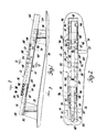
- a seat slide structure 10 includes an upper track member 12 and a lower track member 14.
- the upper track member 12 includes a base 16 and a U-shaped leg 18 extending laterally from each side of the base.
- the legs 18 are located inwardly relative to the base 16 and open inwardly toward such base.
- the lower track member 14 likewise includes a.base 26 which is juxtaposed to the base 16 of the upper track member and U-shaped legs 28 which interfit with the legs 18.
- Each leg 28 includes an inner leg portion 30 juxtaposed to an inner terminal leg portion 22 of a leg 18 of the upper track member and an outer terminal leg portion 32 which interfits between the leg portions 20 and 22 of a respective leg 18 of the upper track member.
- the leg portions 30 and 32 are joined to each other across bights 34.
- Front and rear plastic slide assemblies interfit between the upper and lower track members 12 and 14 in order to slidably mount the upper track member 12 on the lower track member.
- Each such slide assembly includes a pair of slides 36 which fit between the base 16 of the upper track member and the bights 34 of the lower track member.
- Each slide includes a groove 38 slidably engaging a respective bight 34.
- the slides space the U-shaped legs 18 and 28 vertically and horizontally laterally of each other without binding.
- the slides 36 are integrally connected to each other by an integral web 40. This web includes a thickened portion 42 at one end thereof which is cut away to provide a vertically extending slotted groove 43 and a recess 44 for purposes to be described.
- the slide assemblies are alike and asymmetrically arranged.
- Each slide 36 as shown in Figure 2 includes a spaced pair of grooved recesses -46 which receive slightly indented integral ribs 48 of the base 16 of the upper track member to locate the slides longitudinally relative to the upper track member.
- the upper and lower track members 12 and 14 can be formed of sheet metal in a rolling mill or extruded.
- the ribs 48 can be formed before the upper track member is passed through the rolls.
- the slides 36 can be moulded of any- generally self-lubricating synthetic plastics material and it will be again: noted that the slides are alike although they are asymmetrically located with respect to each other.
- a generally H-shaped light weight latch member 50 is located within the upper track member 12 above the bights 34 of the lower track member.
- the latch member 50 includes spaced pairs of outwardly extending locking legs 52 which extend outwardly of legs 18 through vertically elongated slots 54. The cooperation of the locking portions 52 and slots 54 locates the latch member 50 longitudinally of the upper track member and mounts the latch member 50 on the upper track member for vertical reciprocating movement between locked and released positions as will be described.
- the latch member is located laterally of the upper track member by a portion or extension 56 thereof extending into the lateral groove 43 of the web 40 of the front slide assembly.
- a bowed leaf spring 58 fits between the latch member 50 and the base 16 of the upper track member 12 to bias the latch member 50 downwardly to locked position.
- the bent ends of the spring 58 are anchored in slots 60 in the base 16 of the upper track member.
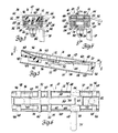
- the locking portions 52 thereof are received within successive pairs of laterally aligned locking notches 62 which are provided in the bights 34 of the lower track member 14 and in the edges of leg portions 22 of legsl8, Figure 3.
- This locking feature is aided by gravity and the bias of the spring 58.
- a release lever 64 includes a pair of oppositely extending ear portions 66 which extend outwardly through transversely aligned slots 68 in the legs 18 in order to mount the release lever 64 to the upper track member.
- the slots 68 are slightly vertically larger than the thickness of the portions 66 to permit a slight tilting movement of the release lever.
- the release lever further includes an extension 70 which is received within the vertical slotted groove 43 of the rear slide assembly in order to position the lever 64 laterally of the upper track member, Figure 6.
- the lever 64 also includes an arcuate end portion 72 which underlies the latch member 50 and is spaced therefrom.
- a suitable manually operable handle, not shown, is secured to an extension 74 of one portion 66 of the release lever 64.
- the lever 64 Upon operation of this handle, the lever 64 is slightly tilted upwardly about the floating pivotal connection provided by portions 66 and slots 68 to in turn engage and shift the latch member 50 vertically upwardly as portions 52 move within slots 54 and out of engagement with the locking notches 62 of the lower track member. This releases the upper track member 12 and the slide assemblies for movement as a unit relative to the lower track member 14 to another horizontally adjusted position. Since the end portion 72 of lever 64 is spaced from latch member 50, gravity and the bias of spring 58 do not act on lever 64 but act only on latch member 50 to maintain it in locked position. Since the latch member 50 is of light weight, such as 7 grams, it has low inertia. Therefore, it is unlikely that the latch member will ratchet past one or more of the slots 54 should the upper track be subjected to high loading from acceleration forces.
- the lower track member is mountable on a floor pan 76 of a body by means of front and rear brackets 78 of generally open U section.
- the lower legs of these brackets are suitably bolted at 80 to the floor pan as shown in Figure 2 while the upper legs are bolted at 82 to the base 26 of the lower track member.
- the heads of the bolts 82 are located above the base 26 of the lower track member. The engagement of these heads with the recesses 44 of the webs 40 of the front and rear pairs of slide assemblies respectively provide rear and front stops limiting movement of the upper track member 12 relative to the lower track member 14.
- This invention provides an improved seat slide structure.
Landscapes
- Engineering & Computer Science (AREA)
- Aviation & Aerospace Engineering (AREA)
- Transportation (AREA)
- Mechanical Engineering (AREA)
- Seats For Vehicles (AREA)
Applications Claiming Priority (2)
| Application Number | Priority Date | Filing Date | Title |
|---|---|---|---|
| US06/510,374 US4487459A (en) | 1983-07-01 | 1983-07-01 | Seat slide structure |
| US510374 | 1995-08-02 |
Publications (2)
| Publication Number | Publication Date |
|---|---|
| EP0130714A2 true EP0130714A2 (de) | 1985-01-09 |
| EP0130714A3 EP0130714A3 (de) | 1987-11-04 |
Family
ID=24030491
Family Applications (1)
| Application Number | Title | Priority Date | Filing Date |
|---|---|---|---|
| EP84303926A Withdrawn EP0130714A3 (de) | 1983-07-01 | 1984-06-11 | Sitzschienenaufbau |
Country Status (2)
| Country | Link |
|---|---|
| US (1) | US4487459A (de) |
| EP (1) | EP0130714A3 (de) |
Cited By (1)
| Publication number | Priority date | Publication date | Assignee | Title |
|---|---|---|---|---|
| DE10156805B4 (de) * | 2000-11-21 | 2010-07-01 | Aisin Seiki K.K., Kariya | Sitzgleitvorrichtung für ein Fahrzeug |
Families Citing this family (16)
| Publication number | Priority date | Publication date | Assignee | Title |
|---|---|---|---|---|
| US4556186A (en) * | 1983-08-15 | 1985-12-03 | General Motors Corporation | Seat adjuster |
| US4730804A (en) * | 1984-10-26 | 1988-03-15 | Honda Giken Kogyo Kabushiki Kaisha | Seat slide rail device |
| US4711589A (en) * | 1986-03-31 | 1987-12-08 | General Motors Corporation | Manual seat adjuster with cam lock |
| JPH0636995Y2 (ja) * | 1988-03-24 | 1994-09-28 | アイシン精機株式会社 | シートレール |
| GB2219933A (en) * | 1988-06-21 | 1989-12-28 | Ti Cox Ltd | Seat slide assembly characterised by the configuration of the interengaging members |
| FR2638797B1 (fr) * | 1988-11-10 | 1991-02-08 | Cousin Cie Ets A & M Freres | Profil de glissieres permettant la realisation de glissieres a verrou flottant |
| US5224749A (en) * | 1992-04-30 | 1993-07-06 | Itt Automotive, Inc. | One-piece upper track for a power seat adjuster |
| US5292164A (en) * | 1992-12-23 | 1994-03-08 | Itt Corporation | Power seat adjuster with horizontal slot drive |
| US5344114A (en) * | 1993-03-31 | 1994-09-06 | Itt Corporation | Vehicle seat adjuster |
| US5499788A (en) * | 1993-03-31 | 1996-03-19 | Itt Corporation | Manual seat adjuster |
| US5507552A (en) * | 1994-01-04 | 1996-04-16 | Itt Corporation | Rotatable seat belt buckle mounting bracket for a vehicle seat adjuster with a catcher bracket buckle brace |
| US5741000A (en) * | 1995-09-13 | 1998-04-21 | Atoma International, Inc. | Vehicle seat track assembly |
| US6886797B2 (en) * | 2001-11-01 | 2005-05-03 | Lear Corporation | Seat track assembly |
| DE60306113T2 (de) * | 2002-01-28 | 2007-01-11 | Intier Automotive, Inc., Novi | Fahrzeugsitzgleitschiene mit höhenverstellbarem lager |
| US20060207729A1 (en) * | 2005-03-17 | 2006-09-21 | Fu-Lai Yu | Control mechanism for a window covering |
| US8215602B2 (en) * | 2008-05-23 | 2012-07-10 | Lear Corporation | Longitudinal adjustment apparatus for a vehicle seat |
Family Cites Families (11)
| Publication number | Priority date | Publication date | Assignee | Title |
|---|---|---|---|---|
| US2927627A (en) * | 1958-05-12 | 1960-03-08 | Gen Motors Corp | Vehicle seat adjuster |
| US3171698A (en) * | 1962-08-29 | 1965-03-02 | Hancock Ind Inc | Seat slide mechanism |
| US3393019A (en) * | 1963-06-10 | 1968-07-16 | Ford Motor Co | Seat adjusting mechanism |
| US3279737A (en) * | 1964-04-13 | 1966-10-18 | Atwood Vacuum Machine Co | Seat slide construction |
| US3350046A (en) * | 1965-12-28 | 1967-10-31 | Hancock Ind Inc | Seat slide assembly for automotive vehicles |
| GB1216207A (en) * | 1968-08-27 | 1970-12-16 | English Steel Corp Ltd | Improvements in or relating to methods and machines for grinding crankshafts |
| IT1044871B (it) * | 1972-11-13 | 1980-04-21 | Sessa T | Guila scorrevole per sedile di autoveicolo |
| DE7319398U (de) * | 1973-05-23 | 1974-03-28 | Hammerstein C Gmbh | Gleitschienenfuehrung fuer fahrzeugsitze |
| DE2545763B2 (de) * | 1975-10-13 | 1979-06-21 | Ausscheidung in: 25 59 653 C Rob. Hammerstein GmbH, 5650 Solingen | Gleitschlenenfiihnuig für längs verschiebbare Fahrzeugsitze |
| DE2702576C2 (de) * | 1977-01-22 | 1982-11-11 | C. Rob. Hammerstein Gmbh, 5650 Solingen | Gleitschienenführung für Fahrzeugsitze |
| JPS5855011B2 (ja) * | 1978-10-09 | 1983-12-07 | 立川スプリング株式会社 | スライドレ−ルを内蔵一体化したシ−トフレ−ムのロツク装置 |
-
1983
- 1983-07-01 US US06/510,374 patent/US4487459A/en not_active Expired - Fee Related
-
1984
- 1984-06-11 EP EP84303926A patent/EP0130714A3/de not_active Withdrawn
Cited By (1)
| Publication number | Priority date | Publication date | Assignee | Title |
|---|---|---|---|---|
| DE10156805B4 (de) * | 2000-11-21 | 2010-07-01 | Aisin Seiki K.K., Kariya | Sitzgleitvorrichtung für ein Fahrzeug |
Also Published As
| Publication number | Publication date |
|---|---|
| US4487459A (en) | 1984-12-11 |
| EP0130714A3 (de) | 1987-11-04 |
Similar Documents
| Publication | Publication Date | Title |
|---|---|---|
| EP0130714A2 (de) | Sitzschienenaufbau | |
| EP0846066B1 (de) | Gleitschienenvorrichtung für fahrzeuge | |
| EP0705178B1 (de) | Sitzgleiteinrichtung | |
| US6322036B1 (en) | Seat track assembly having a locking mechanism with infinite engagement | |
| US3964798A (en) | Safety belt anchorages | |
| US6286799B1 (en) | Slide device for vehicle seat | |
| US4837976A (en) | Window balance spring cover friction system | |
| US4165126A (en) | Adjustable vehicle seat bottom | |
| EP0076041A1 (de) | Fahrzeugsitzverstellvorrichtung | |
| EP1116625A2 (de) | Zusatzsitz | |
| EP1902191A2 (de) | Türrollensystem | |
| EP0209615A1 (de) | Sitzgleiteinrichtung für Autositz | |
| US6578810B2 (en) | Seat slide apparatus | |
| CN113954704B (zh) | 儿童安全座椅 | |
| CA2176426C (en) | Seat track apparatus | |
| EP0510622B1 (de) | Sitzverstellungsvorrichtung mit ineinandergreifenden Schienen | |
| US6435465B1 (en) | Seat adjuster | |
| US4520982A (en) | Slide adjustment apparatus | |
| US5050907A (en) | Adjustable seat belt anchorage | |
| US6105921A (en) | Adjustable seat mounting mechanism | |
| US5219230A (en) | Vehicle seat slides | |
| EP0117131A2 (de) | Längsverschiebemechanik für einen Fahrzeugsitz | |
| US5011242A (en) | Drawer guide assembly | |
| EP0549380B1 (de) | Sitzaufhängung mit einem Endanschlaggleitelement für automatische Gleitspalteinstellung | |
| EP0436366B1 (de) | Fahrzeugsitzgleitführung |
Legal Events
| Date | Code | Title | Description |
|---|---|---|---|
| PUAI | Public reference made under article 153(3) epc to a published international application that has entered the european phase |
Free format text: ORIGINAL CODE: 0009012 |
|
| AK | Designated contracting states |
Designated state(s): DE FR GB IT SE |
|
| PUAL | Search report despatched |
Free format text: ORIGINAL CODE: 0009013 |
|
| STAA | Information on the status of an ep patent application or granted ep patent |
Free format text: STATUS: THE APPLICATION HAS BEEN WITHDRAWN |
|
| AK | Designated contracting states |
Kind code of ref document: A3 Designated state(s): DE FR GB IT SE |
|
| 18W | Application withdrawn |
Withdrawal date: 19871012 |
|
| RIN1 | Information on inventor provided before grant (corrected) |
Inventor name: REES, RICHARD WILLIAM ARTHUR |