EP0130722B1 - Elektrische Leitungsanrichtung - Google Patents
Elektrische Leitungsanrichtung Download PDFInfo
- Publication number
- EP0130722B1 EP0130722B1 EP84304064A EP84304064A EP0130722B1 EP 0130722 B1 EP0130722 B1 EP 0130722B1 EP 84304064 A EP84304064 A EP 84304064A EP 84304064 A EP84304064 A EP 84304064A EP 0130722 B1 EP0130722 B1 EP 0130722B1
- Authority
- EP
- European Patent Office
- Prior art keywords
- buoy
- circuit assembly
- antenna
- further characterised
- sensor
- Prior art date
- Legal status (The legal status is an assumption and is not a legal conclusion. Google has not performed a legal analysis and makes no representation as to the accuracy of the status listed.)
- Expired
Links
Images


Classifications
-
- B—PERFORMING OPERATIONS; TRANSPORTING
- B63—SHIPS OR OTHER WATERBORNE VESSELS; RELATED EQUIPMENT
- B63B—SHIPS OR OTHER WATERBORNE VESSELS; EQUIPMENT FOR SHIPPING
- B63B22/00—Buoys
- B63B22/003—Buoys adapted for being launched from an aircraft or water vehicle;, e.g. with brakes deployed in the water
-
- B—PERFORMING OPERATIONS; TRANSPORTING
- B29—WORKING OF PLASTICS; WORKING OF SUBSTANCES IN A PLASTIC STATE IN GENERAL
- B29C—SHAPING OR JOINING OF PLASTICS; SHAPING OF MATERIAL IN A PLASTIC STATE, NOT OTHERWISE PROVIDED FOR; AFTER-TREATMENT OF THE SHAPED PRODUCTS, e.g. REPAIRING
- B29C49/00—Blow-moulding, i.e. blowing a preform or parison to a desired shape within a mould; Apparatus therefor
- B29C49/20—Blow-moulding, i.e. blowing a preform or parison to a desired shape within a mould; Apparatus therefor of articles having inserts or reinforcements ; Handling of inserts or reinforcements
- B29C2049/2008—Blow-moulding, i.e. blowing a preform or parison to a desired shape within a mould; Apparatus therefor of articles having inserts or reinforcements ; Handling of inserts or reinforcements inside the article
-
- B—PERFORMING OPERATIONS; TRANSPORTING
- B29—WORKING OF PLASTICS; WORKING OF SUBSTANCES IN A PLASTIC STATE IN GENERAL
- B29L—INDEXING SCHEME ASSOCIATED WITH SUBCLASS B29C, RELATING TO PARTICULAR ARTICLES
- B29L2031/00—Other particular articles
- B29L2031/34—Electrical apparatus, e.g. sparking plugs or parts thereof
- B29L2031/3431—Telephones, Earphones
-
- B—PERFORMING OPERATIONS; TRANSPORTING
- B29—WORKING OF PLASTICS; WORKING OF SUBSTANCES IN A PLASTIC STATE IN GENERAL
- B29L—INDEXING SCHEME ASSOCIATED WITH SUBCLASS B29C, RELATING TO PARTICULAR ARTICLES
- B29L2031/00—Other particular articles
- B29L2031/706—Buoys
Definitions
- This invention in its broadest context, relates to the fabrication of apparatus incorporating an electronic circuit assembly, and to apparatus so fabricated.
- Such apparatus may take many forms and be used in many industries.
- Electronic circuit assemblies commonly include electronic components which are intolerant of high temperature.
- the present invention provides a method of fabricating apparatus comprising an electronic circuit assembly and a housing surrounding said assembly, said circuit assembly including high-temperature-intolerant electronic components, characterised in that said method comprises the steps of: extruding a tube of molten thermoplastic material fully around said circuit assembly; moulding said tube between sections of a mould; and injecting high pressure gas into the interior of said material so as to blow mould a thermoplastic shell around said circuit assembly, said mould sections being cooled and said extruding and moulding steps being performed rapidly enough not to damage electronic components of said circuit assembly.
- the invention also extends to apparatus fabricated by such a method and further characterised in that it comprises a sensor buoy, such as a sonobuoy, having a terminal weight and sensor for deployment beneath the surface of the water after said buoy impacts the water, a cable connecting said sensor to said circuit assembly; and said circuit assembly is arranged to process the output of said sensor, and an antenna is arranged to transmit a signal corresponding to said output.
- a sensor buoy such as a sonobuoy
- said circuit assembly is arranged to process the output of said sensor, and an antenna is arranged to transmit a signal corresponding to said output.
- the blow-moulded housing forms a seamless, watertight flotation compartment for the circuit assembly
- the terminal weight and sensor e.g., hydrophone
- the blow-moulded housing is moulded tightly around the exterior of the ballast cup to provide a water tight seal, even during water impact
- the circuit assembly consists of a vertically-oriented circuit board supported on the ballast cup; an air space separates the board from the housing (which provides insulation from the heat of the blow-moulding process); an antenna is supported on a tab extending through the blow-moulded housing at its top; water cooling is supplied to the moulds used in the blow-moulding process to reduce the temperature elevation of the electronic components; annular grooves are provided on the exterior of the ballast cup for improving the water tightness of the seal to the blow-moulded housing; and aerodynamic fins are moulded into the top of the housing for aerodynamic orientation.
- An antenna attached to the buoy housing may be suitably adapted to be deployed during the free-fall of the buoy, prior to its water impact.
- the antenna is wrapped around the housing; the housing includes a shallow groove for receiving the wrapped- around antenna; the antenna is a blade of greater width than thickness; and the antenna is adapted to provide aerodynamic drag and stability during the buoy's fall.
- a water-impact-actuated release means may be suitably provided comprising a plate extending across the bottom opening of the ballast cup and adapted to release the terminal weight and sensor upon water impact but not upon high inertial loading.
- a weakened region is provided near one tab and the terminal weight is spaced from the plate in the vicinity of that tab so that inertial loading on the weight is resisted by unweakened regions of the plate and so that space is provided between the plate and the weight in the vicinity of the weakened region to enable the water impact force to push the plate inward and thereby break the plate at the weakened region.
- the buoy may have an extended spheroid housing, i.e., one having a cylindrical mid section and semispherical end portions.
- the antenna is connected to the top semispherical portion; the bottom semispherical portion has a flat surface generally at its centre for causing the buoy to dig into the water upon water impact rather than to skip along the surface.
- the teachings of the present invention have numerous advantages, both in relation to buoys and to other forms of apparatus. They can provide a simpler and less costly construction, and one that, in the case of a buoy, can safely be allowed to fall freely (without a parachute or similar drag device) to the water surface. Forming the housing by blow-moulding creates a seamless structure with no high stress points; and it avoids the problem that two-piece construction housings have of fracturing, for example, upon impact. In the case of buoys, the need for reinforcement bands, which complicate the manufacturing process and add to the weight of a sonobuoy, is eliminated; and surprisingly the blow-moulding process, even through an extremely hot process, does not harm the temperature sensitive electronic components.
- blow-moulding provides an excellent seal, one that withstands water impact. Because the buoy antenna is released at launching, it provides additional drag and stability during free flight to ensure that the buoy impacts the water at the desired velocity and in a nose down orientation so that the shear plate will break; launch release also eliminates the need for an antenna release mechanism at impact, which complicates the buoy's manufacture and increases its weight.
- the extended spheroid shape of the buoy housing also has advantages; it provides a high centre of buoyancy and low centre of gravity to reduce the sonobuoy's rolling motion and provide a more stable platform for transmission of the alarm signal, it provides high drag and stability during free fall, it has good impact strength, and the preferred flattened bottom prevents the buoy from skipping across the water at initial impact.
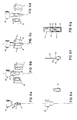
- a sonobuoy consisting of a printed circuit board 1, ballast cup 2, omni-directional hydrophone 3, terminal weight 5, shear plate 7, battery pack 10, transmitting antenna 12, and polyethylene buoy housing 14.
- a conventional transmitter, microprocessor chip 31 TMS 1000, Texas Instruments
- integrated circuit 30 TMS 1000, Texas Instruments
- Three flat pack batteries (6 Volt Polaroid P-80 Polapulse) are contained in case 22 that snaps on to the printed circuit board.
- Antenna tab 13 is riveted to the top of the board. The board is riveted at the bottom to the ballast cup.
- rubber plug 4 attached to the bottom of the board is inserted through a hole in the top surface of the ballast cup.
- This rubber plug acts as a seal when the buoy is in the water.
- the plug houses two salt water electrodes 9 that are connected to the circuit board and that protrudes from the plug's bottom.
- the hydrophone consists of a flexural transducer, which is a small thin piezoelectric ceramic disc 6 mounted on a brass plate. The ceramic disc surface is silvered and an electrode is soldered to this surface. Another electrode is soldered to the brass ring. One end of two conductors in cable 11 is connected to each electrode.
- the transducer is placed on a plastic ring which is cemented into the zinc terminal weight and then potted over. The plastic ring and potting serve-to protect and isolate the connections.
- Kevlar Denier
- the cable at the outside end of the spool is fed through rubber grommet 8 that fits into a hole in the ballast cup and the two wires contained in the cable are connected to the circuit board.
- the terminal weight/hydrophone assembly is placed inside the ballast cup, and shear plate 7, with its two retaining tabs, is inserted into grooves on the inside of the ballast cup.
- the left retaining tab of the shear plate supports the terminal weight and will prevent the terminal weight from prematurely falling out of the ballast cup due to inertial forces during handling before deployment.
- the right retaining tab is scored at 40 (Figs. 2 and 4) and is spaced below the terminal weight as a result of the tapered shape of the bottom of the weight.
- the spacing between the plate and the weight in the vicinity of the weakened (scored) region allows the plate to be pushed inward at water impact, thus tearing or rupturing the plate.
- the space prevents inertial loads on the weight from being applied to the weakened region, thus ensuring that the plate will not accidentally rupture during handling.
- the printed circuit board and ballast cup assembly are placed (Fig. 6a) on a support stand (not shown). While the two halves of housing mould 19 are spaced apart, extruder 20 extrudes a tube of high density polyethylene around the electronics and ballast/hyd- rophone assembly (Fig. 6b). The thickness of the tube varies from 0.100 inches (0.254 cm) at the bottom to 0.075 inches (0.1905 cm) at the top. Next, the two halves of the mould are pressed together (Fig. 6c), compressively moulding the polyethylene around the base of the ballast cup and around tab 13 at the top of the printed circuit board.
- a needle 21 is now inserted into the pinched off tube and high pressure air is blown into the tube, forcing the tube to assume the shape of the inside of the mould.
- This blow moulding operation is a hot process.
- the moulding is done quickly and the moulds themselves are water cooled.
- the result of the blow moulding operation is a one piece seamless housing with no structural weak points.
- the housing is trimmed (Figs. 6d-6f), leaving an extended spheroid (cylindrical middle section with semispherical upper and lower ends) and two stabilizing fins 15.
- Two scuttle plugs 16 (Fig.
- FIG. 6f A shallow groove 42 (Fig. 1) is formed during molding completely around the outside of the housing to form a receptacle for the steel antenna when it is wrapped around the housing and . inserted in launching cylinder 17 (Fig. 6g).
- the components of the signal processor, which controls the detection operation of the sonobuoy, are shown in Fig. 5.
- the hydrophone signal is preamplified, and then filtered and amplified to leave only the signal and noise in the frequency band of interest. Any DC bias is subtracted out through the use of a microprocessor-controlled auto- balance circuit and the resulting AC signal is rectified.
- the amplitude of the AC signal at the analog-to-digital converter input is greater than a threshold voltage stored in the microprocessor, the latter will modulate the transmitter via the alarm output, and the transmitter will send out this signal via the antenna. This will continue for as long as the target is present, or 15 minutes, the life of the batteries. If the transmitter is never used, the batteries will operate the rest of the circuitry for about four hours.
- the buoy is 4.5 inches (11.43 cm) in diameter, 5.6 inches (14.224 cm) in height, and 1.4 Ib (0.555 Kg) in weight. Its centre of gravity is 1.7 inches (4.318 cm) from its base, and its centre of buoyancy is 1.95 inches (4.953 cm) from its base.
- the antenna is 18 inches (45.72 cm) long and 0.5 inches (1.27 cm) wide.
- the sonobuoys are deployed as shown in Fig. 1.
- One buoy at a time is launched from a cylinder (each of which contains six buoys) carried by an aircraft.
- Antenna 12 springs back to its relaxed position upon the sonobuoy's exit from the cylinder, and the antenna acts as a tail to provide, along with the fins, drag and stability for the sonobuoy as it falls freely to the water.
- the fins are particularly helpful to initially orienting the buoy immediately after launch.
- the scored right retaining tab 40 of the shear plate 7 (Fig. 3) will break. This releases the hydrophone/ terminal weight assembly from the ballast cup, allowing the assembly to fall down into the water until the spool of cable completely unwinds.
- the release of the assembly will also expose the salt water electrodes to the salt water, completing a circuit that turns on the power supply.
- the signal processor initializes the system by setting the initial gain of the integrator and the initial threshold level. The sonobuoy is now ready for its normal mode of operation.
- the sonobuoy listens for submarines by measuring the ambient noise detected by the hydrophone across a frequency range. When the detected noise rises above a stored threshold level, the transmitter sends out an alarm signal as long as the target is present or until the battery power runs out. If no submarine is detected, the transmitter is silent. The scuttle plugs will erode after about eight hours, and the sonobuoy will sink.
Landscapes
- Engineering & Computer Science (AREA)
- Mechanical Engineering (AREA)
- Manufacturing & Machinery (AREA)
- Aviation & Aerospace Engineering (AREA)
- Chemical & Material Sciences (AREA)
- Combustion & Propulsion (AREA)
- Ocean & Marine Engineering (AREA)
- Arrangements For Transmission Of Measured Signals (AREA)
- Testing Or Calibration Of Command Recording Devices (AREA)
- Preparation Of Compounds By Using Micro-Organisms (AREA)
- Position Fixing By Use Of Radio Waves (AREA)
- Control And Other Processes For Unpacking Of Materials (AREA)
- Measurement Of Velocity Or Position Using Acoustic Or Ultrasonic Waves (AREA)
- Transmitters (AREA)
- Input Circuits Of Receivers And Coupling Of Receivers And Audio Equipment (AREA)
- Emergency Protection Circuit Devices (AREA)
- Supplying Of Containers To The Packaging Station (AREA)
Claims (20)
Priority Applications (1)
| Application Number | Priority Date | Filing Date | Title |
|---|---|---|---|
| AT84304064T ATE33115T1 (de) | 1983-06-15 | 1984-06-15 | Elektrische leitungsanrichtung. |
Applications Claiming Priority (2)
| Application Number | Priority Date | Filing Date | Title |
|---|---|---|---|
| US50457183A | 1983-06-15 | 1983-06-15 | |
| US504571 | 1983-06-15 |
Publications (2)
| Publication Number | Publication Date |
|---|---|
| EP0130722A1 EP0130722A1 (de) | 1985-01-09 |
| EP0130722B1 true EP0130722B1 (de) | 1988-03-23 |
Family
ID=24006840
Family Applications (1)
| Application Number | Title | Priority Date | Filing Date |
|---|---|---|---|
| EP84304064A Expired EP0130722B1 (de) | 1983-06-15 | 1984-06-15 | Elektrische Leitungsanrichtung |
Country Status (6)
| Country | Link |
|---|---|
| EP (1) | EP0130722B1 (de) |
| JP (1) | JPS6057212A (de) |
| AT (1) | ATE33115T1 (de) |
| AU (1) | AU566156B2 (de) |
| CA (1) | CA1228665A (de) |
| DE (1) | DE3470022D1 (de) |
Families Citing this family (7)
| Publication number | Priority date | Publication date | Assignee | Title |
|---|---|---|---|---|
| CA1286925C (en) * | 1988-05-26 | 1991-07-30 | Murray O. Hill | Sonobuoy cable pack |
| US5073136A (en) * | 1990-03-29 | 1991-12-17 | Magnavox Government And Industrial Electronics Company | Collapsible sonobuoy floatation device |
| GB2250592A (en) * | 1990-12-06 | 1992-06-10 | Marconi Gec Ltd | Underwater acoustic sensing apparatus |
| WO2016068821A1 (en) | 2014-10-31 | 2016-05-06 | Koc Bilgi Ve Savunma Teknolojileri A. S. | Smart buoy which can carry out platform determination and recognition and a determination and recognition method using said buoy |
| CN106965905B (zh) * | 2017-05-18 | 2019-05-17 | 国家海洋技术中心 | 海洋声学测量浮标系统 |
| CN109579916B (zh) * | 2018-12-26 | 2021-09-03 | 中国船舶重工集团公司第七一九研究所 | 一种浮标式声电磁集成探测装置 |
| CN118665654B (zh) * | 2024-06-24 | 2025-10-14 | 北京蔚海明祥科技有限公司 | 一种空投剖面浮标 |
Family Cites Families (6)
| Publication number | Priority date | Publication date | Assignee | Title |
|---|---|---|---|---|
| US3275976A (en) * | 1964-03-26 | 1966-09-27 | Sanders Associates Inc | Bottom release mechanism for a sonobuoy |
| US3424623A (en) * | 1966-06-28 | 1969-01-28 | Michael J Oakley | Blow molded battery |
| US3646505A (en) * | 1970-03-18 | 1972-02-29 | Naval Air Systems Command Usa | Automatically deployable sonobuoy |
| JPS5218039A (en) * | 1975-08-01 | 1977-02-10 | Sumitomo Heavy Industries | Method of bridge erection construction |
| JPS5826094Y2 (ja) * | 1979-10-05 | 1983-06-06 | 敏平 望月 | 柄取機用のバイス順次繰出しによる長柄形成装置 |
| JPS5822141A (ja) * | 1981-07-31 | 1983-02-09 | Sekisui Plastics Co Ltd | 発泡体積層中空成形品の製造方法 |
-
1984
- 1984-06-13 AU AU29347/84A patent/AU566156B2/en not_active Ceased
- 1984-06-14 CA CA000456543A patent/CA1228665A/en not_active Expired
- 1984-06-15 JP JP59123527A patent/JPS6057212A/ja active Pending
- 1984-06-15 EP EP84304064A patent/EP0130722B1/de not_active Expired
- 1984-06-15 DE DE8484304064T patent/DE3470022D1/de not_active Expired
- 1984-06-15 AT AT84304064T patent/ATE33115T1/de not_active IP Right Cessation
Also Published As
| Publication number | Publication date |
|---|---|
| AU2934784A (en) | 1984-12-20 |
| ATE33115T1 (de) | 1988-04-15 |
| EP0130722A1 (de) | 1985-01-09 |
| CA1228665A (en) | 1987-10-27 |
| DE3470022D1 (en) | 1988-04-28 |
| JPS6057212A (ja) | 1985-04-03 |
| AU566156B2 (en) | 1987-10-08 |
Similar Documents
| Publication | Publication Date | Title |
|---|---|---|
| US4673363A (en) | Marine measurement device | |
| US4026188A (en) | Modular buoy system | |
| JP5923169B2 (ja) | 通信ブイおよび展開の方法 | |
| US4189703A (en) | System for deploying a sensor array from transiting vessel | |
| US4493664A (en) | Sonobuoy float inflation and depth selection initiators | |
| US4004265A (en) | Self-propelled array system | |
| US7559288B2 (en) | Recoverable optical fiber tethered buoy assembly | |
| US5073136A (en) | Collapsible sonobuoy floatation device | |
| EP0130722B1 (de) | Elektrische Leitungsanrichtung | |
| US20200013263A1 (en) | Autonomous aircraft locator system | |
| US4208738A (en) | Deployable sonar array with interconnected transducers operated in the bending mode | |
| US4473896A (en) | Tactical Expendable Device | |
| US5456427A (en) | Air-launchable gliding sonobuoy | |
| US3933109A (en) | Buoy releasable from a submarine | |
| US4651834A (en) | Ice penetrating method and apparatus | |
| US4601961A (en) | Bilaminar seawater battery | |
| US3281765A (en) | Miniature sonobuoy and cable | |
| US3946695A (en) | Self-deploying multiple anchor mooring systems | |
| US3788255A (en) | Expendable submarine receiving antenna | |
| AU2021286381B2 (en) | Surface deployed communication buoy | |
| KR102621945B1 (ko) | 부표 | |
| US6982383B1 (en) | Outer casing structure and fabrication method for cable sections and navy buoyant antennas | |
| US4357688A (en) | Low cost sonobuoy | |
| GB2320556A (en) | Gun launchable sensor | |
| US6097668A (en) | Component deployment means for ice penetrating acoustics communication relay system |
Legal Events
| Date | Code | Title | Description |
|---|---|---|---|
| PUAI | Public reference made under article 153(3) epc to a published international application that has entered the european phase |
Free format text: ORIGINAL CODE: 0009012 |
|
| AK | Designated contracting states |
Designated state(s): AT BE CH DE FR GB LI LU NL SE |
|
| 17P | Request for examination filed |
Effective date: 19850708 |
|
| 17Q | First examination report despatched |
Effective date: 19860220 |
|
| GRAA | (expected) grant |
Free format text: ORIGINAL CODE: 0009210 |
|
| AK | Designated contracting states |
Kind code of ref document: B1 Designated state(s): AT BE CH DE FR GB LI LU NL SE |
|
| PG25 | Lapsed in a contracting state [announced via postgrant information from national office to epo] |
Ref country code: LI Effective date: 19880323 Ref country code: CH Effective date: 19880323 |
|
| REF | Corresponds to: |
Ref document number: 33115 Country of ref document: AT Date of ref document: 19880415 Kind code of ref document: T |
|
| PG25 | Lapsed in a contracting state [announced via postgrant information from national office to epo] |
Ref country code: SE Effective date: 19880331 |
|
| REF | Corresponds to: |
Ref document number: 3470022 Country of ref document: DE Date of ref document: 19880428 |
|
| PG25 | Lapsed in a contracting state [announced via postgrant information from national office to epo] |
Ref country code: LU Free format text: LAPSE BECAUSE OF NON-PAYMENT OF DUE FEES Effective date: 19880630 |
|
| REG | Reference to a national code |
Ref country code: CH Ref legal event code: PL |
|
| ET | Fr: translation filed | ||
| PLBE | No opposition filed within time limit |
Free format text: ORIGINAL CODE: 0009261 |
|
| STAA | Information on the status of an ep patent application or granted ep patent |
Free format text: STATUS: NO OPPOSITION FILED WITHIN TIME LIMIT |
|
| 26N | No opposition filed | ||
| PGFP | Annual fee paid to national office [announced via postgrant information from national office to epo] |
Ref country code: AT Payment date: 19890627 Year of fee payment: 6 |
|
| PGFP | Annual fee paid to national office [announced via postgrant information from national office to epo] |
Ref country code: NL Payment date: 19890630 Year of fee payment: 6 Ref country code: GB Payment date: 19890630 Year of fee payment: 6 |
|
| PGFP | Annual fee paid to national office [announced via postgrant information from national office to epo] |
Ref country code: BE Payment date: 19890725 Year of fee payment: 6 |
|
| PGFP | Annual fee paid to national office [announced via postgrant information from national office to epo] |
Ref country code: LU Payment date: 19890802 Year of fee payment: 6 |
|
| PGFP | Annual fee paid to national office [announced via postgrant information from national office to epo] |
Ref country code: DE Payment date: 19890831 Year of fee payment: 6 |
|
| PG25 | Lapsed in a contracting state [announced via postgrant information from national office to epo] |
Ref country code: GB Effective date: 19900615 Ref country code: AT Effective date: 19900615 |
|
| PG25 | Lapsed in a contracting state [announced via postgrant information from national office to epo] |
Ref country code: BE Effective date: 19900630 |
|
| BERE | Be: lapsed |
Owner name: SIPPICAN OCEAN SYSTEMS INC. Effective date: 19900630 |
|
| PG25 | Lapsed in a contracting state [announced via postgrant information from national office to epo] |
Ref country code: NL Effective date: 19910101 |
|
| GBPC | Gb: european patent ceased through non-payment of renewal fee | ||
| NLV4 | Nl: lapsed or anulled due to non-payment of the annual fee | ||
| PG25 | Lapsed in a contracting state [announced via postgrant information from national office to epo] |
Ref country code: DE Effective date: 19910403 |
|
| PGFP | Annual fee paid to national office [announced via postgrant information from national office to epo] |
Ref country code: FR Payment date: 19910619 Year of fee payment: 8 |
|
| PG25 | Lapsed in a contracting state [announced via postgrant information from national office to epo] |
Ref country code: FR Effective date: 19930226 |
|
| REG | Reference to a national code |
Ref country code: FR Ref legal event code: ST |