EP0130742A2 - Appareil de combustion à gaz à allure élevée - Google Patents
Appareil de combustion à gaz à allure élevée Download PDFInfo
- Publication number
- EP0130742A2 EP0130742A2 EP84304192A EP84304192A EP0130742A2 EP 0130742 A2 EP0130742 A2 EP 0130742A2 EP 84304192 A EP84304192 A EP 84304192A EP 84304192 A EP84304192 A EP 84304192A EP 0130742 A2 EP0130742 A2 EP 0130742A2
- Authority
- EP
- European Patent Office
- Prior art keywords
- air
- flame
- mixture
- ports
- port section
- Prior art date
- Legal status (The legal status is an assumption and is not a legal conclusion. Google has not performed a legal analysis and makes no representation as to the accuracy of the status listed.)
- Granted
Links
Images




Classifications
-
- F—MECHANICAL ENGINEERING; LIGHTING; HEATING; WEAPONS; BLASTING
- F23—COMBUSTION APPARATUS; COMBUSTION PROCESSES
- F23D—BURNERS
- F23D14/00—Burners for combustion of a gas, e.g. of a gas stored under pressure as a liquid
- F23D14/26—Burners for combustion of a gas, e.g. of a gas stored under pressure as a liquid with provision for a retention flame
-
- F—MECHANICAL ENGINEERING; LIGHTING; HEATING; WEAPONS; BLASTING
- F23—COMBUSTION APPARATUS; COMBUSTION PROCESSES
- F23D—BURNERS
- F23D14/00—Burners for combustion of a gas, e.g. of a gas stored under pressure as a liquid
- F23D14/30—Inverted burners, e.g. for illumination
-
- F—MECHANICAL ENGINEERING; LIGHTING; HEATING; WEAPONS; BLASTING
- F23—COMBUSTION APPARATUS; COMBUSTION PROCESSES
- F23D—BURNERS
- F23D14/00—Burners for combustion of a gas, e.g. of a gas stored under pressure as a liquid
- F23D14/34—Burners specially adapted for use with means for pressurising the gaseous fuel or the combustion air
- F23D14/36—Burners specially adapted for use with means for pressurising the gaseous fuel or the combustion air in which the compressor and burner form a single unit
-
- F—MECHANICAL ENGINEERING; LIGHTING; HEATING; WEAPONS; BLASTING
- F23—COMBUSTION APPARATUS; COMBUSTION PROCESSES
- F23D—BURNERS
- F23D14/00—Burners for combustion of a gas, e.g. of a gas stored under pressure as a liquid
- F23D14/46—Details
- F23D14/48—Nozzles
- F23D14/58—Nozzles characterised by the shape or arrangement of the outlet or outlets from the nozzle, e.g. of annular configuration
-
- F—MECHANICAL ENGINEERING; LIGHTING; HEATING; WEAPONS; BLASTING
- F23—COMBUSTION APPARATUS; COMBUSTION PROCESSES
- F23D—BURNERS
- F23D14/00—Burners for combustion of a gas, e.g. of a gas stored under pressure as a liquid
- F23D14/46—Details
- F23D14/62—Mixing devices; Mixing tubes
Definitions
- This invention relates to a high load gas combustion apparatus for use mainly in domestic combustors, in which a fan is used to forcibly supply air for burning to promote combustion reaction and shorten a flame length, thus achieving reduction in size of the combustion chamber and hence the entire apparatus, and in which the fan is a relatively small-sized fan to provide low supply pressure for ensuring combustion at a low noise level.
- Fresh air passes both sides of the burner body 1 from a supply chamber 5 and then reaches a fresh air chamber 6.
- Some fresh air is supplied to the combustion chamber 4 through parallel air ports 7 which comprise a number of relatively small holes and are arranged near the flame ports 3, while the remaining fresh air is supplied to the combustion chamber 4 through oblique air ports 9 which comprise a number of relatively large holes and are arranged in an oblique plate 8.
- the present invention is further intended to ensure still greater reduction both in size of the entire combustion apparatus and in noise level by such a construction that the flame section comprises flat plates bent in the direction perpendicular to the direction of flow of the mixture into a zigzag form so as to make contact with each other at the central part of the flame port section, thus reducing the jet speed of a mixture due to the increased flame port area and making the jet speed of a mixture on both sides of the flame port section near the air ports higher than that of a mixture at the center thereof, or that a porous flat plate is bent into the polygonal or parabolic form to be projected into the combustion chamber, thus causing some of the mixture to jet in the direction toward the air ports.
- Another object of the present invention is to achieve perfect combustion with a smaller air excess ratio at all times even under remarkable variations of the combustion rate by arranging the zigzag-like air ports with the crest portion projecting toward the downstream side in the form of a spire so as to supply a larger quantity of secondary air on the upstream side so that the flame zone is always formed along the air ports in accordance with the combustion rate.
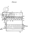
- a fan 13 for supplying air for burning is attached to one end of a burner case 14 at one side thereof.
- a nozzle 15 for jetting fuel is provided to one end of the burner case 14 at the other side thereof to face a mixing tube 16.
- the mixing tube 16 is connected to a mixing tube connection box 17 so as to constitute a mixing tube section 18.
- a mixture tube connection box 17 is connected to two mixture chambers 2 each defined by a burner body 1 which is formed of a drawn aluminum material and has a uniform shape in the lengthwise direction.
- a porous equalizing plate 20 is inserted in each of the mixture chambers 2.
- a flame port section 3' which comprises a nubmer of flame ports 3 and has a large opening ratio, to be held between the side walls of the burner body 1 for partition of the mixture chambers 2 from the downward combustion chambers 4.
- Flame retention chambers 21 are formed on both sides of the flame port section 3' by providing recesses la at parts of the burner body 1.
- a plurality of air chambers 6 defined by both the burner bodies 1 and the burner case 14 are formed on both sides of the mixture chambers 2.
- a porous rectifying plate 22 is inserted on the downstream side of each air chamber 6.
- air jet plates 8 are provided to form a partition between the combustion chambers 4 and the air chambers 6.
- each air jet plate 8 there are bored a number of air ports 9 arranged in zigzag form at the oblique portion thereof, and a number of flame retention air ports 7 arranged in the lengthwise direction of the flame port section 3' at the horizontal portion thereof. Further, a number of small projections 23 are provided between the air ports 9 and the flame retention air ports 7 to form small gaps 24 between the small projections 23 and the part of the burner body 1 constituting the flame retention chambers 21.
- a heat exchanger 25 inside an exhaust hood 26.
- the majority of secondary air supplied from each of the air chambers 6 is directly jetted and supplied into the combustion at a relatively high speed making an angle relative to the flow of mixture also flowing into the combustion chamber 4.
- the remaining secondary air is supplied to the flame retention chambers 21 through the small gaps 24.
- the small gaps 24 are very narrow passages, this renders a large pressure loss so that the flame retention chambers 21 have lower pressure than the air chambers 6. Accordingly, the secondary air flowing into the combustion chamber 4 from both sides of each flame port section 3' through the flame retention air ports 7 has a lower flow speed so as not to disturb the root of the flame, whereby flame retention is further ensured.
- Fig. 5a shows the case where the air ports 9 comprising a number of small holes are arranged in zigzag form.
- a mixture flow A is first deflected by the secondary air jetted through the air ports 9 on the upstream side to be divided into different small mixture masses following an arrangement of the zigzag-like air ports 9 with a certain appropriate spacing between the adjacent masses.
- the individual small mixture masses thus divided are continuously supplied with secondary air through the downstream air ports 9 arranged bifurcately, while flowing downwardly.
- the resultant flame B becomes a steady flame which is formed following an arrangement of the air ports 9 even in case of using gas fuel having smaller combustion velocity, so that flame surface area or combustion reaction area is greatly enlarged and combustion is completed at the more upstream side. It is thus possible to make smaller the flame length without the need to make provision for the secondary air jetted through the air ports 9 to have a particularly high jet speed. Further, because the individual small mixture masses are spaced from one another with an appropriate spacing, the flame size will never be increased due to flame interference. This permits the lowering of the air blowing pressure of the fan 13 and a remarkable reduction of noise level with effective flame retention and steady flames. It becomes also possible to use the combustion apparatus universally for various types of gas fuel having different physical properties. Fig.
- FIG. 5b shows a flame C which is formed in a case where the air ports 9 are arranged in zigzag form using two types of slit holes.
- High-temperature gas having completed combustion undergoes heat exchange in the heat exchanger 25 to become exhaust gas which is collected into the exhaust hood 26 and then discharged to the atmosphere through an exhaust tube (not shown).
- Figs. 6a and 6b show another embodiment in which flat plates are bent into zigzag form and arranged so that an S-like flame port 3 comes into contact with an inverted S-like flame port 3 at the central part of the flame port section 3'.
- the flame port section 3' has a larger flame port area at both side ends thereof than that at the central part of the flame port section 3' where the flat plates are contacted with each other, the flowout rate of mixture at both side ends of each flame port near the air ports 9 is larger than that at the central part thereof. Accordingly, even if the secondary air jetted through the air ports 9 is caused to have a smaller jet speed, the secondary air can be supplied sufficiently up to the center of the mixture flow, thus achieving a still further reduction of noise level.
- Fig. 7 shows still another embodiment in which the flame port section 3' is so constructed that a porous plate including a number of small holes as flame ports 3 is bent into the polygonal form to be projected to the combustion chamber size.
- the flame port section 3' is so constructed that a porous plate including a number of small holes as flame ports 3 is bent into the polygonal form to be projected to the combustion chamber size.
- Fig. 8a shows another embodiment in which the air ports 9 comprising a number of small holes arranged in zigzag form are arranged to have a diverging angle a at the crest portion thereof, smaller than a diverging angle S at the root portion thereof.
- a flame D formed along the air ports 9 is supplied with a larger quantity of secondary air at the more upstream side, so that combustion will be correspondingly completed at the more upstream side.
- the flow speed of a mixture A' becomes so small that the mixture will not reach the air ports 9 at the crest portion and a flame E is formed only at the root portion, as shown in Fig. 8b.
- Fig. 8c shows an embodiment in which the air ports are arranged in zigzag form likewise using two types of slit holes 9.
Landscapes
- Engineering & Computer Science (AREA)
- Chemical & Material Sciences (AREA)
- Combustion & Propulsion (AREA)
- Mechanical Engineering (AREA)
- General Engineering & Computer Science (AREA)
- Gas Burners (AREA)
Applications Claiming Priority (6)
| Application Number | Priority Date | Filing Date | Title |
|---|---|---|---|
| JP58113725A JPS604716A (ja) | 1983-06-23 | 1983-06-23 | 高負荷バ−ナ |
| JP113725/83 | 1983-06-23 | ||
| JP113286/83U | 1983-07-20 | ||
| JP11328683U JPS6021826U (ja) | 1983-07-20 | 1983-07-20 | 燃焼装置 |
| JP58169635A JPS6062505A (ja) | 1983-09-14 | 1983-09-14 | 燃焼装置 |
| JP169635/83 | 1983-09-14 |
Publications (3)
| Publication Number | Publication Date |
|---|---|
| EP0130742A2 true EP0130742A2 (fr) | 1985-01-09 |
| EP0130742A3 EP0130742A3 (en) | 1985-09-18 |
| EP0130742B1 EP0130742B1 (fr) | 1988-08-17 |
Family
ID=27312471
Family Applications (1)
| Application Number | Title | Priority Date | Filing Date |
|---|---|---|---|
| EP84304192A Expired EP0130742B1 (fr) | 1983-06-23 | 1984-06-21 | Appareil de combustion à gaz à allure élevée |
Country Status (3)
| Country | Link |
|---|---|
| US (1) | US4610626A (fr) |
| EP (1) | EP0130742B1 (fr) |
| DE (1) | DE3473501D1 (fr) |
Cited By (7)
| Publication number | Priority date | Publication date | Assignee | Title |
|---|---|---|---|---|
| FR2589555A1 (fr) * | 1985-11-06 | 1987-05-07 | Gaz De France | Bruleur a gaz a air souffle |
| EP0250668A1 (fr) * | 1986-07-01 | 1988-01-07 | British Gas Corporation | Brûleur à combustible, en particulier gazeux |
| FR2603092A1 (fr) * | 1986-08-22 | 1988-02-26 | Osaka Gas Co Ltd | Bruleur a gaz |
| US4923393A (en) * | 1985-06-13 | 1990-05-08 | British Gas Corporation | Fuel fired burner |
| US5059115A (en) * | 1985-06-13 | 1991-10-22 | British Gas Plc | Fuel fired burner |
| IT201700090904A1 (it) * | 2017-08-04 | 2019-02-04 | Dometic Sweden Ab | Apparato di riscaldamento per un veicolo ricreativo |
| WO2019025633A1 (fr) * | 2017-08-04 | 2019-02-07 | Dometic Sweden Ab | Appareil de chauffage pour véhicule de loisirs |
Families Citing this family (9)
| Publication number | Priority date | Publication date | Assignee | Title |
|---|---|---|---|---|
| DE3868406D1 (de) * | 1988-07-26 | 1992-03-26 | Maxon Int | Brenner fuer trocknungs- oder gasreinigungsprozesse. |
| US4993944A (en) * | 1988-09-02 | 1991-02-19 | Cambridge Engineering, Inc. | Direct gas-fired burner assembly |
| US5083918A (en) * | 1988-09-02 | 1992-01-28 | Cambridge Engineering, Inc. | Direct gas-fired burner assembly |
| US6526964B1 (en) | 1999-05-20 | 2003-03-04 | Cambridge Engineering, Inc. | Direct gas-fired burner assembly |
| KR100659678B1 (ko) * | 1999-08-17 | 2006-12-21 | 닛폰화네스코교 가부시기가이샤 | 연소 방법 및 버너 |
| ITMI20020449A1 (it) * | 2002-03-04 | 2003-09-04 | Fondital Fonderie Italiane Nuo | Bruciatore a gas e radiatore a gas equipaggiato con tale bruciatore |
| US7631678B2 (en) * | 2005-08-04 | 2009-12-15 | Soprema Inc. | Hot air device for thermowelding bitumen membranes |
| KR100778716B1 (ko) * | 2006-07-07 | 2007-11-22 | 주식회사 경동나비엔 | 가스버너의 염공부 구조 |
| US20100294257A1 (en) * | 2009-05-15 | 2010-11-25 | Robert Thayer | Direct-fired heating system |
Family Cites Families (5)
| Publication number | Priority date | Publication date | Assignee | Title |
|---|---|---|---|---|
| US2647569A (en) * | 1951-05-24 | 1953-08-04 | John H Flynn | Ribbon-type gas burner-unit |
| US3494711A (en) * | 1968-06-28 | 1970-02-10 | Eclipse Fuel Eng Co | Burner for heating a gaseous medium having a low oxygen content |
| US3592578A (en) * | 1970-01-23 | 1971-07-13 | Weather Rite Mfg | Gas burners |
| DE2839627C2 (de) * | 1977-09-13 | 1983-11-03 | Hitachi, Ltd., Tokyo | Gasbrenner |
| FR2481415A1 (fr) * | 1980-04-23 | 1981-10-30 | Fulpin Jacques | Bruleur a gaz |
-
1984
- 1984-06-20 US US06/622,744 patent/US4610626A/en not_active Expired - Lifetime
- 1984-06-21 EP EP84304192A patent/EP0130742B1/fr not_active Expired
- 1984-06-21 DE DE8484304192T patent/DE3473501D1/de not_active Expired
Cited By (11)
| Publication number | Priority date | Publication date | Assignee | Title |
|---|---|---|---|---|
| US4923393A (en) * | 1985-06-13 | 1990-05-08 | British Gas Corporation | Fuel fired burner |
| US5059115A (en) * | 1985-06-13 | 1991-10-22 | British Gas Plc | Fuel fired burner |
| FR2589555A1 (fr) * | 1985-11-06 | 1987-05-07 | Gaz De France | Bruleur a gaz a air souffle |
| EP0223691A1 (fr) * | 1985-11-06 | 1987-05-27 | Gaz De France | Brûleur à gaz à air soufflé |
| US4752213A (en) * | 1985-11-06 | 1988-06-21 | Gaz De France | Forced-air gas burner |
| EP0250668A1 (fr) * | 1986-07-01 | 1988-01-07 | British Gas Corporation | Brûleur à combustible, en particulier gazeux |
| EP0381252A3 (en) * | 1986-07-01 | 1990-10-10 | British Gas Plc | Fuel fired burner |
| FR2603092A1 (fr) * | 1986-08-22 | 1988-02-26 | Osaka Gas Co Ltd | Bruleur a gaz |
| IT201700090904A1 (it) * | 2017-08-04 | 2019-02-04 | Dometic Sweden Ab | Apparato di riscaldamento per un veicolo ricreativo |
| WO2019025633A1 (fr) * | 2017-08-04 | 2019-02-07 | Dometic Sweden Ab | Appareil de chauffage pour véhicule de loisirs |
| WO2019025634A1 (fr) * | 2017-08-04 | 2019-02-07 | Dometic Sweden Ab | Appareil de chauffage et procédé de chauffage d'air et d'eau dans un véhicule de loisirs, et véhicule de loisirs |
Also Published As
| Publication number | Publication date |
|---|---|
| DE3473501D1 (en) | 1988-09-22 |
| EP0130742A3 (en) | 1985-09-18 |
| US4610626A (en) | 1986-09-09 |
| EP0130742B1 (fr) | 1988-08-17 |
Similar Documents
| Publication | Publication Date | Title |
|---|---|---|
| US4610626A (en) | High load gas combustion apparatus | |
| US3051464A (en) | Air-heating gas burner | |
| US5318438A (en) | Burner low in the generation of nitrogen oxides and a small combustion apparatus | |
| CN211782004U (zh) | 火排单体、燃烧器和燃气设备 | |
| JP2930858B2 (ja) | 燃焼装置 | |
| EP4596963A1 (fr) | Brûleur à gaz et dispositif de brûleur à gaz | |
| JP3477935B2 (ja) | 低騒音濃淡燃焼装置 | |
| JP4459112B2 (ja) | バーナ装置及びこれを備えた媒体加熱装置 | |
| JP3620646B2 (ja) | ガス燃焼装置 | |
| JP2956215B2 (ja) | 燃焼装置 | |
| JPH11294719A (ja) | 表面燃焼バーナ用ウインドボックス | |
| JPH0330662Y2 (fr) | ||
| JP2956229B2 (ja) | 燃焼装置 | |
| JPH07293836A (ja) | 窒素酸化物低発生バーナ装置 | |
| JPH0332684B2 (fr) | ||
| JPH0318814Y2 (fr) | ||
| JPS6234098Y2 (fr) | ||
| JPH0424258Y2 (fr) | ||
| JPS6347693Y2 (fr) | ||
| JPH0619216B2 (ja) | ガスバ−ナ | |
| JP2001124312A (ja) | 燃焼装置 | |
| JP2805000B2 (ja) | 燃焼装置 | |
| JPS6115014A (ja) | 高負荷燃焼装置 | |
| JPH0882406A (ja) | 燃焼装置 | |
| JPS6234099Y2 (fr) |
Legal Events
| Date | Code | Title | Description |
|---|---|---|---|
| PUAI | Public reference made under article 153(3) epc to a published international application that has entered the european phase |
Free format text: ORIGINAL CODE: 0009012 |
|
| AK | Designated contracting states |
Designated state(s): DE FR GB |
|
| PUAL | Search report despatched |
Free format text: ORIGINAL CODE: 0009013 |
|
| AK | Designated contracting states |
Designated state(s): DE FR GB |
|
| 17P | Request for examination filed |
Effective date: 19851106 |
|
| 17Q | First examination report despatched |
Effective date: 19860924 |
|
| GRAA | (expected) grant |
Free format text: ORIGINAL CODE: 0009210 |
|
| AK | Designated contracting states |
Kind code of ref document: B1 Designated state(s): DE FR GB |
|
| REF | Corresponds to: |
Ref document number: 3473501 Country of ref document: DE Date of ref document: 19880922 |
|
| ET | Fr: translation filed | ||
| PLBE | No opposition filed within time limit |
Free format text: ORIGINAL CODE: 0009261 |
|
| STAA | Information on the status of an ep patent application or granted ep patent |
Free format text: STATUS: NO OPPOSITION FILED WITHIN TIME LIMIT |
|
| 26N | No opposition filed | ||
| REG | Reference to a national code |
Ref country code: GB Ref legal event code: 746 Effective date: 19960628 |
|
| PGFP | Annual fee paid to national office [announced via postgrant information from national office to epo] |
Ref country code: FR Payment date: 20000612 Year of fee payment: 17 |
|
| PGFP | Annual fee paid to national office [announced via postgrant information from national office to epo] |
Ref country code: DE Payment date: 20000619 Year of fee payment: 17 |
|
| PGFP | Annual fee paid to national office [announced via postgrant information from national office to epo] |
Ref country code: GB Payment date: 20000621 Year of fee payment: 17 |
|
| PG25 | Lapsed in a contracting state [announced via postgrant information from national office to epo] |
Ref country code: GB Free format text: LAPSE BECAUSE OF NON-PAYMENT OF DUE FEES Effective date: 20010621 |
|
| GBPC | Gb: european patent ceased through non-payment of renewal fee |
Effective date: 20010621 |
|
| PG25 | Lapsed in a contracting state [announced via postgrant information from national office to epo] |
Ref country code: FR Free format text: LAPSE BECAUSE OF NON-PAYMENT OF DUE FEES Effective date: 20020228 |
|
| PG25 | Lapsed in a contracting state [announced via postgrant information from national office to epo] |
Ref country code: DE Free format text: LAPSE BECAUSE OF NON-PAYMENT OF DUE FEES Effective date: 20020403 |