EP0130800A2 - Heizsystem von Hochofen mit elektrischer Beheizung - Google Patents
Heizsystem von Hochofen mit elektrischer Beheizung Download PDFInfo
- Publication number
- EP0130800A2 EP0130800A2 EP84304401A EP84304401A EP0130800A2 EP 0130800 A2 EP0130800 A2 EP 0130800A2 EP 84304401 A EP84304401 A EP 84304401A EP 84304401 A EP84304401 A EP 84304401A EP 0130800 A2 EP0130800 A2 EP 0130800A2
- Authority
- EP
- European Patent Office
- Prior art keywords
- arc
- gas
- burden
- heated gas
- shaft
- Prior art date
- Legal status (The legal status is an assumption and is not a legal conclusion. Google has not performed a legal analysis and makes no representation as to the accuracy of the status listed.)
- Withdrawn
Links
Images

Classifications
-
- C—CHEMISTRY; METALLURGY
- C21—METALLURGY OF IRON
- C21B—MANUFACTURE OF IRON OR STEEL
- C21B5/00—Making pig-iron in the blast furnace
- C21B5/001—Injecting additional fuel or reducing agents
- C21B5/002—Heated electrically (plasma)
-
- C—CHEMISTRY; METALLURGY
- C21—METALLURGY OF IRON
- C21B—MANUFACTURE OF IRON OR STEEL
- C21B7/00—Blast furnaces
-
- C—CHEMISTRY; METALLURGY
- C21—METALLURGY OF IRON
- C21B—MANUFACTURE OF IRON OR STEEL
- C21B5/00—Making pig-iron in the blast furnace
- C21B5/06—Making pig-iron in the blast furnace using top gas in the blast furnace process
-
- Y—GENERAL TAGGING OF NEW TECHNOLOGICAL DEVELOPMENTS; GENERAL TAGGING OF CROSS-SECTIONAL TECHNOLOGIES SPANNING OVER SEVERAL SECTIONS OF THE IPC; TECHNICAL SUBJECTS COVERED BY FORMER USPC CROSS-REFERENCE ART COLLECTIONS [XRACs] AND DIGESTS
- Y02—TECHNOLOGIES OR APPLICATIONS FOR MITIGATION OR ADAPTATION AGAINST CLIMATE CHANGE
- Y02P—CLIMATE CHANGE MITIGATION TECHNOLOGIES IN THE PRODUCTION OR PROCESSING OF GOODS
- Y02P10/00—Technologies related to metal processing
- Y02P10/25—Process efficiency
Definitions
- This invention relates to a blast furnace system for the production of iron or ferroalloys utilizing an electric arc heater to heat a reducing gas or fuel which is injected through the furnace tuyeres into the furnace charge or burden allowing for a reduction in the amount of coke which is normally used in the iron-making process.
- the blast furnace is the world's primary apparatus for the reduction of iron-bearing materials, such as iron ore, into pig iron.
- Blast furnaces represent very old technology and have been the subject of major scale-up efforts over the past 20 years.
- coke is combusted in the furnace with preheated air to provide heat and a reducing gas for the reduction reaction involving the iron-bearing material.
- Existing blast furnace systems employ a refractory lined vertical shaft furnace having gas uptakes attached to the top of the shaft, a gas separator, blast air heating stoves, and injection tuyeres.
- the upper, middle and lower regions of the shaft are known as the stack, bosh and hearth, respectively.
- a mixture of iron-bearing materials, coke and flux which is known as burden, is introduced at the top 0 6 the furnace. This burden slowly descends against an upwardly rising flow of reducing gas.
- Preheated blast air or wind is introduced into the charge through water-cooled tuyeres combusting the coke to produce carbon monoxide and heat.
- the carbon monoxide reduces the iron-bearing materials into iron which is then melted by the heat liberated by the combustion of the coke and a portion of the heat contained in the blast air.
- the melted iron and slag which is produced by the reduction reactions are collected in the hearth from which they are removed via outlets known as iron notches and slag notches, respectively.
- Excess reducing gas and heat rises upwardly through the stack to cause the preheating and pre-reduction of the burden contained therein.
- This reducing gas and heat exits the top of the furnace and enters the gas uptakes. At this stage these gases are typically referred to as off-gases. These off-gases are then directed into a gas separator for the removal of substantially all entrained particulate materials.
- the cleaned off-gases are sent to the blast air heating stoves where they are combusted to heat the blast air which will be injected through the tuyeres.
- This blast air is heated in the stoves to a temperature of approximately 1000°C.
- a blast furnace system for reducing metal and metal ore, comprises a blast furnace means with stack means for having metal ore reduced therein, said stack means having an exhaust port, electric arc heater means disposed in communication with an internal portion of said stack means for supplying arc-heated gas containing reductants thereto for reducing said metal ore, a portion of the arc-heated gas exiting the stack at said exhaust port, and electrical generating means interconnected with the exhaust port to receive said portion of the arc-heated gas, said portion of the arc-heated gas being utilized in the electrical generating means to produce electrical energy, the electrical energy being supplied to the electrical arc heater means for energization thereof.
- the blast furnace system utilizing an electric arc heater to superheat a fluid such as blast air or a reducing gas which is then injected into the blast furnace via the tuyeres allowing for a substantial decrease in the coke rate required for the production of iron.
- a fluid such as blast air or a reducing gas
- the blast furnace system utilizing an electric arc heater to superheat a fluid such as blast air or a reducing gas which is then injected into the blast furnace via the tuyeres allowing for a substantial decrease in the coke rate required for the production of iron.
- a combustion turbine-generator set is used to produce the required electricity.
- the off-gases from the blast furnace are combusted in the turbine driving the output shaft of the turbine which in turn drives the generator to produce the electricity.
- the off-gases Prior to their entry into the combustion turbine, the off-gases can be cleaned of entrained particulates in a gas scrubber.
- a steam turbine-driven compressor can then be used to compress these clean gases prior to their entry into the combustion turbine to increase operating efficiency.
- the heat released in the combustion turbine is directed into a heat exchanger wherein steam is produced to drive the steam turbine.
- This arrangement of equipment forms an essentially closed-loop system utilizing the blast furnace off-gases to provide electricity for the electric arc heater.
- injection of coal into the blast air is utilized.
- the coal and blast air are superheated by the electric arc heater causing the formation of carbon monoxide, a reducing gas which is used to reduce the iron-bearing materials.
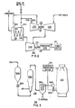
- Fig. 1 shows a blast furnace 5 with a refractory shell 7 defining a vertical shaft, the upper, middle and lower regions thereof being known as the stack 9, bosh 11 and hearth 13, respectively with a shell 7 being supported by the base 8.
- a tuyere 17 disposed about the lower end of the bosh 11 is used to introduce a reducing gas into the burden 19 contained in the shaft.
- the refractory shell 7 includes an outer wall 21 and a refractory lining 23 with the upper portion of the shell 7 being tapered inwardly and upwardly and being closed at the upper end by a bell-shaped cover 25 through which the burden 19 is dumped into the furnace 5.
- the burden 19 or charge consists primarily of a metal ore, a fuel, and flux, examples of which are iron ore, coke and limestone, respectively. These materials descend countercurrent to the gases rising in the furnace until they reach the bosh 11 which is the region of highest temperature. Maximum reduction of the ore to elemental metal occurs in the bosh 11 with the metal draining to the hearth 13 from where it is tapped or removed from time to time. Slag which is produced by the reduction reaction also drains into the hearth 13 and floats on the top of the molten metal.
- a blast furnace may be operated with a single tuyere, normally a plurality of tuyeres as shown in Fig. 1 are disposed about the lower portion of the bosh 11.
- a conduit or bustle pipe 29 is connected to each tuyere 17 forming a plenum or header for the delivery of gas to the tuyeres 17 for injection into the furnace 5.
- an electric arc heater is provided intermediate each tuyere 17 and the bustle pipe 29.
- the inlet 52 of the electric arc heater 50 is in communication with the bustle pipe 29 via a conduit 31 with the outlet 54 being in communication with the tail end 33 of the tuyere 17.
- the electric arc heater 50 has at least one electrode and an arcing chamber, the electrode adapted to be connected to a source of electrical potential to produce an electric arc in the arcing chamber. Where two or more electrodes are provided these are typically cylindrical in shape with an annular cross-section. There the electrodes are axially spaced from one another to form an annular gap wherein the electric arc is generated.
- the electric arc heater 50 is either a self-stabilizing DC or single phase AC device capable of power levels to about 5000 kilowatts. Because the electric arc heater 50 is similar in construction and operation to the electric arc heater disclosed in the specification of U.S. Patent Nos. 3,663,792, and 4,247,732, the description of the arc heater 50 is limited herein to the basic structure and operation.
- a gaseous mixture of a carbon fuel and an oxygen containing gas is introduced into the bustle pipe 29 and enters through the inlet 52 of the electric arc heater for heating by the electric arc in the arcing chamber.
- This heating forms a superheated gas stream containing a reducing gas, such as carbon monoxide, having a temperature in the range of about 2000°C to about 2500°C.
- the arc heated gas stream exits the outlet 54 of the electric arc heater 50 and is injected into the bosh 11 via the tuyere 17 where it contacts the burden 19 in the furnace.
- the arc heated gas stream reacts with the burden 19 to produce metal and slag with the metal and slag being collected in the hearth 13.
- the gases pass upwardly through the burden 19 entraining particulates and cause the prereduction and preheating of the burden 19 in the stack 9.
- the gas can be superheated by the arc heater with the fuel being injected into the superheated gas stream.
- the carbon fuel can be natural gas, oil, or preferably, finely divided coal with the oxygen-containing gas being air.
- the oxygen-containing gas usually contains some moisture which is present in the gases in the furnace in the form of water vapor, typically superheated steam. This water vapor and excess arc heated gas, termed off-gases exit the top of the furnace and enter the gas uptake 27 from where it is conveyed to the gas scrubber 35.
- these off-gases are cleaned of substantially all entrained particulates and water vapor.
- This cleaning process may be a single-stage process or a two-stage process, the latter having a primary stage to remove coarser particles and a secondary or final stage to remove as much of the remaining particulates as possible.
- the off-gases then enter a wet cleaner 37 such as a venturi washer. There the gases are washed with water to remove any residual particulates as well as reducing the temperature of the off-gases to about the temperature of the wash water. Any moisture in excess of saturation at this temperature is precipitated thus eliminating the water which was carried over in the off-gases.
- the temperature of the wash water is typically ambient.
- the cleaned and cooled off-gases are conveyed to the electrical generating system 41 wherein these cleaned gases are combusted to produce electricity which is transmitted to the power supply 43 for the electric arc heater 50.
- blast furnace is disclosed and described as being used for the reduction of iron ore to elemental iron, it is understood that the furnace or similar furnace with some modifications may be used for the reduction of other ores of metals such as copper, lead, tin and zinc or ferroalloys such as ferromanganese.
- the electrical generating system generally indicated at 100 consists of a turbine-driven compressor system 102, a combustion turbine-generator set 104 and a heat exchanger 106.
- the cleaned cooled gases exiting the scrubber enter the gas compressor 102A, are compressed therein and sent to the combustion turbine 104A.
- the combustion of the gases in the combustion turbine 104A causes the rotation of the output shaft 105 of the turbine which in turn rotates the generator 104B to produce electricity which is transmitted via conductor 107 to,the power supply 108 for the arc heater.
- an alternate source of electrical power (not shown) can be connected to the power supply 108 to operate the arc heater. When off-gas volume is sufficient to operate the generator, this alternate power source is disconnected.
- the products of combustion in the combustion turbine 104A are exhausted into the primary side 106A of the heat exchanger 106 for the recovery of the heat energy contained therein.
- the inlet 106C and outlet 106D of the secondary side 106B of the heat exchanger 106 are connected to the outlet 102D and inlet 102C, respectively, of the steam turbine 102B.
- a heat exchange medium preferably water is contained in the secondary side 106B and is vaporized by the heat it receives from the gases passing through the primary side 106A of the heat exchanger 106.
- the products of combustion are exhausted from the primary side 106A and vented to atmosphere.
- the vaporized medium exits the outlet 106D of the secondary side 106B of the heat exchanger 106 and enters the inlet 102C of the steam turbine 102B causing the rotation of the output shaft 103 thereof which drives the compressor 102A.
- the vaporized medium condenses in the turbine 102B and is recirculated back into the secondary side 106B of the heat exchanger 106.
- a supply of make-up water 110 can be provided in the conduit connecting the outlet 102D of the steam turbine 102B and the inlet 106C of the heat exchanger 106 to account for losses in the heat exchanger medium.
- a blast furnace system generally indicated at 200, utilizing coal injection is shown.
- the blast furnace system is comprised of a blast furnace 202, an electrical generating system 204 and a coal injection system generally indicated at 206.
- the blast furnace 202 and electrical generating system are substantially the same as the blast furnace of Fig. 1 and the electrical generating system of Fig. 2, respectively, both of which are described hereinabove.
- the coal injection system 206 is used to form a gaseous mixture of finely divided coal and air which is directed into the electric arc heater.
- a tank 206A is provided for holding a supply of finely divided coal.
- the coal is discharged from the tank 206A by gravity, or pneumatic or vibratory methods through the valve 206B which is used to control the discharge rate and conveyed to a fluidizing reactor 206C via conventional conveying means such as a pneumatic conveyor.
- air is introduced via a gas inlet and is mixed with the coal to form a fluidized mixture which is then exhausted via the outlet of the reactor 206C into a cyclone separator 206D.
- There the particles of coal, larger than minus 48 mesh, are separated from the coal-air mixture by cyclonic swirling.
- the remaining mixture is transferred into the arc heater 202A via the bustle pipe 202B for heating to form the reducing gas.
- coal which is used can be of any type thus reducing the need for high quality metallurgical coking coal.
- the various embodiments exemplary of the invention present an essentially closed loop blast furnace system providing the dual advantage of a reduction in the coke rate necessary to produce iron by the injection of arc-heated reducing gases while simultaneously eliminating the necessity of purchasing utility generated power during normal operations by producing the electricity for the arc heater from the combustion of the off-gases exhausted from the furnace.
Landscapes
- Engineering & Computer Science (AREA)
- Chemical & Material Sciences (AREA)
- Manufacturing & Machinery (AREA)
- Materials Engineering (AREA)
- Metallurgy (AREA)
- Organic Chemistry (AREA)
- Vertical, Hearth, Or Arc Furnaces (AREA)
- Furnace Details (AREA)
- Manufacture Of Iron (AREA)
Applications Claiming Priority (2)
| Application Number | Priority Date | Filing Date | Title |
|---|---|---|---|
| US06/509,121 US4509177A (en) | 1983-06-29 | 1983-06-29 | Electric arc-fired blast furnace system |
| US509121 | 1995-07-31 |
Publications (2)
| Publication Number | Publication Date |
|---|---|
| EP0130800A2 true EP0130800A2 (de) | 1985-01-09 |
| EP0130800A3 EP0130800A3 (de) | 1985-04-24 |
Family
ID=24025355
Family Applications (1)
| Application Number | Title | Priority Date | Filing Date |
|---|---|---|---|
| EP84304401A Withdrawn EP0130800A3 (de) | 1983-06-29 | 1984-06-28 | Heizsystem von Hochofen mit elektrischer Beheizung |
Country Status (6)
| Country | Link |
|---|---|
| US (1) | US4509177A (de) |
| EP (1) | EP0130800A3 (de) |
| JP (1) | JPS6036608A (de) |
| KR (1) | KR850000532A (de) |
| BR (1) | BR8403092A (de) |
| CA (1) | CA1236151A (de) |
Families Citing this family (7)
| Publication number | Priority date | Publication date | Assignee | Title |
|---|---|---|---|---|
| US5322544A (en) * | 1992-05-29 | 1994-06-21 | Nucor Corporation | Melting a mixture of scrap metal using scrap rubber |
| US5695543A (en) * | 1996-05-10 | 1997-12-09 | D & S Technologies, Inc. | Method for metal reduction of steel waste products |
| US20040000147A1 (en) * | 2001-01-23 | 2004-01-01 | Reginald Wintrell | Systems and methods for harvesting energy from direct iron-making off gases |
| US6519942B2 (en) * | 2001-01-23 | 2003-02-18 | Reginald Wintrell | Systems and methods for harvesting energy from direct iron-making off gases |
| US20060157899A1 (en) * | 2005-01-15 | 2006-07-20 | Lew Holdings, Llc | Single vessel blast furnace and steel making/gasifying apparatus and process |
| CA2698251C (en) * | 2007-09-04 | 2014-06-03 | Cardero Resource Corporation | Direct processing of metallic ore concentrates into ferroalloys |
| AT506640B1 (de) * | 2008-03-17 | 2010-07-15 | Siemens Vai Metals Tech Gmbh | Verfahren und vorrichtung zur herstellung von flüssigem roheisen oder flüssigen stahlvorprodukten |
Family Cites Families (8)
| Publication number | Priority date | Publication date | Assignee | Title |
|---|---|---|---|---|
| US823561A (en) * | 1905-01-28 | 1906-06-19 | Enrique A Touceda | Metallurgical apparatus. |
| GB958731A (en) * | 1962-06-29 | 1964-05-27 | Ass Elect Ind | Means for supplying heated air to blast furnaces |
| US3663792A (en) * | 1970-03-02 | 1972-05-16 | Westinghouse Electric Corp | Apparatus and method of increasing arc voltage and gas enthalpy in a self-stabilizing arc heater |
| BE752793A (en) * | 1970-06-30 | 1970-12-30 | Centre Rech Metallurgique | Injecting hot reducing gas into a blast furn- - ace |
| BE756555A (en) * | 1970-09-23 | 1971-03-23 | Centre Rech Metallurgique | Introducing heated reformed gas into a - furnace |
| US4017272A (en) * | 1975-06-05 | 1977-04-12 | Bamag Verfahrenstechnik Gmbh | Process for gasifying solid carbonaceous fuel |
| US4247732A (en) * | 1979-08-21 | 1981-01-27 | Westinghouse Electric Corp. | Method and apparatus for electrically firing an iron blast furnace |
| BR8200062A (pt) * | 1981-01-15 | 1982-10-26 | Asea Ltd | Processo de recuperacao de energia a partir de corrente de gas residual de vaso de processamento metalurgico e instalacao para producao de ferro ou aco pelo dito processo |
-
1983
- 1983-06-29 US US06/509,121 patent/US4509177A/en not_active Expired - Lifetime
-
1984
- 1984-06-14 CA CA000456563A patent/CA1236151A/en not_active Expired
- 1984-06-25 BR BR8403092A patent/BR8403092A/pt unknown
- 1984-06-28 EP EP84304401A patent/EP0130800A3/de not_active Withdrawn
- 1984-06-28 JP JP59134991A patent/JPS6036608A/ja active Pending
- 1984-06-29 KR KR1019840003714A patent/KR850000532A/ko not_active Withdrawn
Also Published As
| Publication number | Publication date |
|---|---|
| JPS6036608A (ja) | 1985-02-25 |
| BR8403092A (pt) | 1985-05-28 |
| KR850000532A (ko) | 1985-02-27 |
| CA1236151A (en) | 1988-05-03 |
| US4509177A (en) | 1985-04-02 |
| EP0130800A3 (de) | 1985-04-24 |
Similar Documents
| Publication | Publication Date | Title |
|---|---|---|
| US4087274A (en) | Method of producing a partially reduced product from finely-divided metal sulphides | |
| KR19980040225A (ko) | 용융선철 및 용융강 예비생성물을 생산하기 위한 방법 및 장치 | |
| JPS62267409A (ja) | 集積ミル装置及びその操作方法 | |
| US5258054A (en) | Method for continuously producing steel or semi-steel | |
| JPH07150211A (ja) | 粉鉱又は精鉱を直接還元するための方法及び装置 | |
| US4530101A (en) | Electric arc fired cupola for remelting of metal chips | |
| JPH01195226A (ja) | 溶融還元方法 | |
| CN117858967A (zh) | 用于生产铁产品的冶金设备的运行方法 | |
| RU2263714C2 (ru) | Способ и устройство для получения чугуна или жидких стальных продуктов из шихты, содержащей железную руду | |
| US4509177A (en) | Electric arc-fired blast furnace system | |
| US4094665A (en) | Method for simultaneous combined production of electrical energy and crude iron | |
| CN114561504B (zh) | 基于流化预还原的熔分装置及熔分方法 | |
| PL178175B1 (pl) | Żeliwiak z zamkniętym obiegiem gazu | |
| WO2005083130A1 (en) | Direct smelting plant and process | |
| CN101792840B (zh) | 一种含铁物料喷射还原炉及含铁物料喷射还原工艺 | |
| JP2016536468A (ja) | コークス乾式消火システムにおける鋼鉄製造 | |
| CN113969329A (zh) | 降低二氧化碳排放的金属还原冶炼方法及系统 | |
| JPH10506682A (ja) | 液体銑鉄もしくは液体前製品及び海綿の製造方法及びこの方法を実行するためのプラント | |
| CN114990274B (zh) | 一种粉状铁矿气基/氢基悬浮还原粉状dri装置系统 | |
| JPS63241125A (ja) | 溶融還元炉からの吸引排ガスを用いた粉鉱石の予備還元方法及び装置 | |
| US3822125A (en) | Flash smelting of iron ore and concentrate | |
| CN217438274U (zh) | 基于流化预还原的熔分装置 | |
| US6200518B1 (en) | Melt-reducing facility and method of operation thereof | |
| CN117127024B (zh) | 红土镍矿流态化煤基预还原矿热熔分系统及铁水制备方法 | |
| JPH01162711A (ja) | 溶融還元法 |
Legal Events
| Date | Code | Title | Description |
|---|---|---|---|
| PUAI | Public reference made under article 153(3) epc to a published international application that has entered the european phase |
Free format text: ORIGINAL CODE: 0009012 |
|
| AK | Designated contracting states |
Designated state(s): BE DE FR GB IT |
|
| PUAL | Search report despatched |
Free format text: ORIGINAL CODE: 0009013 |
|
| AK | Designated contracting states |
Designated state(s): BE DE FR GB IT |
|
| 17P | Request for examination filed |
Effective date: 19851024 |
|
| 17Q | First examination report despatched |
Effective date: 19861010 |
|
| D17Q | First examination report despatched (deleted) | ||
| STAA | Information on the status of an ep patent application or granted ep patent |
Free format text: STATUS: THE APPLICATION IS DEEMED TO BE WITHDRAWN |
|
| 18D | Application deemed to be withdrawn |
Effective date: 19880412 |
|
| RIN1 | Information on inventor provided before grant (corrected) |
Inventor name: FEY, MAURICE GERARD |