EP0130812A1 - Vorrichtung zum Steuern des Gangwechsels in automatischen Getrieben - Google Patents
Vorrichtung zum Steuern des Gangwechsels in automatischen Getrieben Download PDFInfo
- Publication number
- EP0130812A1 EP0130812A1 EP84304443A EP84304443A EP0130812A1 EP 0130812 A1 EP0130812 A1 EP 0130812A1 EP 84304443 A EP84304443 A EP 84304443A EP 84304443 A EP84304443 A EP 84304443A EP 0130812 A1 EP0130812 A1 EP 0130812A1
- Authority
- EP
- European Patent Office
- Prior art keywords
- gear
- time
- actuator assembly
- gear position
- interval
- Prior art date
- Legal status (The legal status is an assumption and is not a legal conclusion. Google has not performed a legal analysis and makes no representation as to the accuracy of the status listed.)
- Granted
Links
Images



Classifications
-
- F—MECHANICAL ENGINEERING; LIGHTING; HEATING; WEAPONS; BLASTING
- F16—ENGINEERING ELEMENTS AND UNITS; GENERAL MEASURES FOR PRODUCING AND MAINTAINING EFFECTIVE FUNCTIONING OF MACHINES OR INSTALLATIONS; THERMAL INSULATION IN GENERAL
- F16H—GEARING
- F16H59/00—Control inputs to control units of change-speed- or reversing-gearings for conveying rotary motion
-
- F—MECHANICAL ENGINEERING; LIGHTING; HEATING; WEAPONS; BLASTING
- F16—ENGINEERING ELEMENTS AND UNITS; GENERAL MEASURES FOR PRODUCING AND MAINTAINING EFFECTIVE FUNCTIONING OF MACHINES OR INSTALLATIONS; THERMAL INSULATION IN GENERAL
- F16H—GEARING
- F16H61/00—Control functions within control units of change-speed- or reversing-gearings for conveying rotary motion ; Control of exclusively fluid gearing, friction gearing, gearings with endless flexible members or other particular types of gearing
- F16H61/12—Detecting malfunction or potential malfunction, e.g. fail safe ; Circumventing or fixing failures
-
- B—PERFORMING OPERATIONS; TRANSPORTING
- B60—VEHICLES IN GENERAL
- B60W—CONJOINT CONTROL OF VEHICLE SUB-UNITS OF DIFFERENT TYPE OR DIFFERENT FUNCTION; CONTROL SYSTEMS SPECIALLY ADAPTED FOR HYBRID VEHICLES; ROAD VEHICLE DRIVE CONTROL SYSTEMS FOR PURPOSES NOT RELATED TO THE CONTROL OF A PARTICULAR SUB-UNIT
- B60W10/00—Conjoint control of vehicle sub-units of different type or different function
- B60W10/02—Conjoint control of vehicle sub-units of different type or different function including control of driveline clutches
-
- B—PERFORMING OPERATIONS; TRANSPORTING
- B60—VEHICLES IN GENERAL
- B60W—CONJOINT CONTROL OF VEHICLE SUB-UNITS OF DIFFERENT TYPE OR DIFFERENT FUNCTION; CONTROL SYSTEMS SPECIALLY ADAPTED FOR HYBRID VEHICLES; ROAD VEHICLE DRIVE CONTROL SYSTEMS FOR PURPOSES NOT RELATED TO THE CONTROL OF A PARTICULAR SUB-UNIT
- B60W10/00—Conjoint control of vehicle sub-units of different type or different function
- B60W10/10—Conjoint control of vehicle sub-units of different type or different function including control of change-speed gearings
- B60W10/11—Stepped gearings
-
- B—PERFORMING OPERATIONS; TRANSPORTING
- B60—VEHICLES IN GENERAL
- B60W—CONJOINT CONTROL OF VEHICLE SUB-UNITS OF DIFFERENT TYPE OR DIFFERENT FUNCTION; CONTROL SYSTEMS SPECIALLY ADAPTED FOR HYBRID VEHICLES; ROAD VEHICLE DRIVE CONTROL SYSTEMS FOR PURPOSES NOT RELATED TO THE CONTROL OF A PARTICULAR SUB-UNIT
- B60W30/00—Purposes of road vehicle drive control systems not related to the control of a particular sub-unit, e.g. of systems using conjoint control of vehicle sub-units
- B60W30/18—Propelling the vehicle
- B60W30/19—Improvement of gear change, e.g. by synchronisation or smoothing gear shift
-
- F—MECHANICAL ENGINEERING; LIGHTING; HEATING; WEAPONS; BLASTING
- F16—ENGINEERING ELEMENTS AND UNITS; GENERAL MEASURES FOR PRODUCING AND MAINTAINING EFFECTIVE FUNCTIONING OF MACHINES OR INSTALLATIONS; THERMAL INSULATION IN GENERAL
- F16H—GEARING
- F16H61/00—Control functions within control units of change-speed- or reversing-gearings for conveying rotary motion ; Control of exclusively fluid gearing, friction gearing, gearings with endless flexible members or other particular types of gearing
-
- B—PERFORMING OPERATIONS; TRANSPORTING
- B60—VEHICLES IN GENERAL
- B60W—CONJOINT CONTROL OF VEHICLE SUB-UNITS OF DIFFERENT TYPE OR DIFFERENT FUNCTION; CONTROL SYSTEMS SPECIALLY ADAPTED FOR HYBRID VEHICLES; ROAD VEHICLE DRIVE CONTROL SYSTEMS FOR PURPOSES NOT RELATED TO THE CONTROL OF A PARTICULAR SUB-UNIT
- B60W2710/00—Output or target parameters relating to a particular sub-units
- B60W2710/02—Clutches
- B60W2710/021—Clutch engagement state
-
- B—PERFORMING OPERATIONS; TRANSPORTING
- B60—VEHICLES IN GENERAL
- B60W—CONJOINT CONTROL OF VEHICLE SUB-UNITS OF DIFFERENT TYPE OR DIFFERENT FUNCTION; CONTROL SYSTEMS SPECIALLY ADAPTED FOR HYBRID VEHICLES; ROAD VEHICLE DRIVE CONTROL SYSTEMS FOR PURPOSES NOT RELATED TO THE CONTROL OF A PARTICULAR SUB-UNIT
- B60W2710/00—Output or target parameters relating to a particular sub-units
- B60W2710/10—Change speed gearings
- B60W2710/1005—Transmission ratio engaged
-
- F—MECHANICAL ENGINEERING; LIGHTING; HEATING; WEAPONS; BLASTING
- F16—ENGINEERING ELEMENTS AND UNITS; GENERAL MEASURES FOR PRODUCING AND MAINTAINING EFFECTIVE FUNCTIONING OF MACHINES OR INSTALLATIONS; THERMAL INSULATION IN GENERAL
- F16H—GEARING
- F16H59/00—Control inputs to control units of change-speed- or reversing-gearings for conveying rotary motion
- F16H59/68—Inputs being a function of gearing status
- F16H2059/6807—Status of gear-change operation, e.g. clutch fully engaged
-
- F—MECHANICAL ENGINEERING; LIGHTING; HEATING; WEAPONS; BLASTING
- F16—ENGINEERING ELEMENTS AND UNITS; GENERAL MEASURES FOR PRODUCING AND MAINTAINING EFFECTIVE FUNCTIONING OF MACHINES OR INSTALLATIONS; THERMAL INSULATION IN GENERAL
- F16H—GEARING
- F16H61/00—Control functions within control units of change-speed- or reversing-gearings for conveying rotary motion ; Control of exclusively fluid gearing, friction gearing, gearings with endless flexible members or other particular types of gearing
- F16H61/12—Detecting malfunction or potential malfunction, e.g. fail safe ; Circumventing or fixing failures
- F16H2061/1204—Detecting malfunction or potential malfunction, e.g. fail safe ; Circumventing or fixing failures for malfunction caused by simultaneous engagement of different ratios resulting in transmission lock state or tie-up condition
-
- F—MECHANICAL ENGINEERING; LIGHTING; HEATING; WEAPONS; BLASTING
- F16—ENGINEERING ELEMENTS AND UNITS; GENERAL MEASURES FOR PRODUCING AND MAINTAINING EFFECTIVE FUNCTIONING OF MACHINES OR INSTALLATIONS; THERMAL INSULATION IN GENERAL
- F16H—GEARING
- F16H61/00—Control functions within control units of change-speed- or reversing-gearings for conveying rotary motion ; Control of exclusively fluid gearing, friction gearing, gearings with endless flexible members or other particular types of gearing
- F16H61/12—Detecting malfunction or potential malfunction, e.g. fail safe ; Circumventing or fixing failures
- F16H2061/1208—Detecting malfunction or potential malfunction, e.g. fail safe ; Circumventing or fixing failures with diagnostic check cycles; Monitoring of failures
-
- F—MECHANICAL ENGINEERING; LIGHTING; HEATING; WEAPONS; BLASTING
- F16—ENGINEERING ELEMENTS AND UNITS; GENERAL MEASURES FOR PRODUCING AND MAINTAINING EFFECTIVE FUNCTIONING OF MACHINES OR INSTALLATIONS; THERMAL INSULATION IN GENERAL
- F16H—GEARING
- F16H61/00—Control functions within control units of change-speed- or reversing-gearings for conveying rotary motion ; Control of exclusively fluid gearing, friction gearing, gearings with endless flexible members or other particular types of gearing
- F16H61/12—Detecting malfunction or potential malfunction, e.g. fail safe ; Circumventing or fixing failures
- F16H2061/1232—Bringing the control into a predefined state, e.g. giving priority to particular actuators or gear ratios
-
- F—MECHANICAL ENGINEERING; LIGHTING; HEATING; WEAPONS; BLASTING
- F16—ENGINEERING ELEMENTS AND UNITS; GENERAL MEASURES FOR PRODUCING AND MAINTAINING EFFECTIVE FUNCTIONING OF MACHINES OR INSTALLATIONS; THERMAL INSULATION IN GENERAL
- F16H—GEARING
- F16H61/00—Control functions within control units of change-speed- or reversing-gearings for conveying rotary motion ; Control of exclusively fluid gearing, friction gearing, gearings with endless flexible members or other particular types of gearing
- F16H61/12—Detecting malfunction or potential malfunction, e.g. fail safe ; Circumventing or fixing failures
- F16H2061/1244—Keeping the current state
-
- F—MECHANICAL ENGINEERING; LIGHTING; HEATING; WEAPONS; BLASTING
- F16—ENGINEERING ELEMENTS AND UNITS; GENERAL MEASURES FOR PRODUCING AND MAINTAINING EFFECTIVE FUNCTIONING OF MACHINES OR INSTALLATIONS; THERMAL INSULATION IN GENERAL
- F16H—GEARING
- F16H61/00—Control functions within control units of change-speed- or reversing-gearings for conveying rotary motion ; Control of exclusively fluid gearing, friction gearing, gearings with endless flexible members or other particular types of gearing
- F16H61/12—Detecting malfunction or potential malfunction, e.g. fail safe ; Circumventing or fixing failures
- F16H2061/1256—Detecting malfunction or potential malfunction, e.g. fail safe ; Circumventing or fixing failures characterised by the parts or units where malfunctioning was assumed or detected
- F16H2061/1288—Detecting malfunction or potential malfunction, e.g. fail safe ; Circumventing or fixing failures characterised by the parts or units where malfunctioning was assumed or detected the failing part is an actuator
-
- F—MECHANICAL ENGINEERING; LIGHTING; HEATING; WEAPONS; BLASTING
- F16—ENGINEERING ELEMENTS AND UNITS; GENERAL MEASURES FOR PRODUCING AND MAINTAINING EFFECTIVE FUNCTIONING OF MACHINES OR INSTALLATIONS; THERMAL INSULATION IN GENERAL
- F16H—GEARING
- F16H61/00—Control functions within control units of change-speed- or reversing-gearings for conveying rotary motion ; Control of exclusively fluid gearing, friction gearing, gearings with endless flexible members or other particular types of gearing
- F16H61/68—Control functions within control units of change-speed- or reversing-gearings for conveying rotary motion ; Control of exclusively fluid gearing, friction gearing, gearings with endless flexible members or other particular types of gearing specially adapted for stepped gearings
- F16H61/682—Control functions within control units of change-speed- or reversing-gearings for conveying rotary motion ; Control of exclusively fluid gearing, friction gearing, gearings with endless flexible members or other particular types of gearing specially adapted for stepped gearings with interruption of drive
Definitions
- the present invention relates to a method of controlling the gear changing operation in an electronically controlled automatic transmission.
- An embodiment of the present invention / provide a method of controlling the gear changing in an which automatic transmission / prevents a gear changing actuator assembly from being damaged and permits a smooth gear changing operation when a temporary lock is produced in a mechanical, hydraulic, or electric system while the gear changing actuator assembly is in operation.
- an interval of time which elapses after the gear changing actuator assembly is operated is measured with a timer, and the measured interval of time is compared with a preset interval of time.
- the gear changing actuator assembly is prevented from being continuously actuated, but returns to its original state to release the temporary lock and then is attempted again the gear changing operation/.
- This process will hereinafter be referred to as a "retry".
- the clutch is connected once to reduce a lock on synchronous meshing. The clutch is connected again to change the meshing phase in a synchromesh system, so that the gear changing operation can easily be effected again.
- an interval of time which elapses after the gear changing actuator assembly is operated from a current gear position "gear position" to another gear position is measured with a timer, the measured interval of time is compared with a preset interval of time, and the operation of the gear changing actuator assembly is stopped and the gear changing actuator assembly is operated to a different gear position from the other gear position or the neutral gear position if the operation of the gear changing actuator assembly is not completed within the preset interval of time. Therefore, when the mechanical, hydraulic, or electric system suffers from a temporary lock during gear changing operation, no undue gear changing operation is continued and the gear changing actuator assembly is not continuously driven.
- FIG. 1 shows an engine 1 including a fuel supply control device (not shown) such as a throttle valve for controlling the amount of an air-fuel mixture introduced into engine cylinders, the engine 1 being connected to a flywheel la.
- a clutch 2 mounted on the flywheel la comprises a known friction clutch having a clutch release lever 2a. The extent to which the clutch 2 is engaged or connected is controlled by a clutch actuator 3 having a piston rod 3a connected to the clutch release lever 2a.
- the clutch actuator 3 is operated by a hydraulic mechanism 4.
- a gear transmission 6 having a synchromesh system is actuated by a gear changing or transmission actuator assembly 5 for effecting desired gear changing operation.
- the gear transmission 6 has an input shaft 6a coupled to the clutch 2, an output shaft (drive shaft) 6b, and a gear position sensor 6c for detecting a selected gear position of the gear transmission 6.
- a select lever 7 which is manipulated by a driver henceforth of a vehicle,hereceforth, "car", incorporating the automatic transmission, is selectively shiftable into an "N" range (neutral position), a “D” range (automatic gear changing position), a “1” range (lst gear position), a “2” range (2nd gear position), a “3” range (automatic gear changing position for lst, 2nd and 3rd gears), and an "R” range (reverse gear position).
- the select lever 7 is associated with a select position sensor 7a for issuing a selection signal SP indicative of a selected range position.
- a rotation sensor 8a is disposed in confronting relation to the input shaft 6a for detecting the number of (rotation speed) r.p.m./of the input shaft 6a.
- a car speed sensor 8b is disposed in confronting relation to the output shaft 6b for detecting the car speed based on the number of r.p.m. of the output shaft 6b.
- An engine rotation sensor 10 is disposed in confronting relation to the flywheel la for detecting the number of r.p.m. of the flywheel la to detect the number of r.p.m. of the engine 1.
- An electronic control system 9 for controlling the automatic transmission comprises a microcomputer composed of a processor 9a for effecting arithmetic operations, a read-only memory (ROM) 9b storing a control program for controlling the gear transmission 6 and the clutch 3, an output port 9c, an input port 9d, a random-access memory (RAM) 9e for storing results of the arithmetic operations, and an address and data bus (BUS) 9f interconnecting the processor 9a, the ROM 9b, the output and input ports 9c, 9d, and the RAM 9e.
- the output port 9c is connected to the clutch actuator 3, the hydraulic mechanism 4, and the gear changing actuator assembly 5 and issues drive signals CDV, PDV, ADV for driving the clutch actuator 3, the hydraulic mechanism 4, and the gear changing actuator assembly 5, respectively.
- the input port 9d. is connected to the gear position sensor 6c, the select position sensor 7a, the rotation sensor 8a, the car speed sensor 8b, the engine rotation sensor 10, an accelerator pedal sensor, a brake pedal sensor, and a water temperature sensor (later described) and receives detected signals respectively from these sensors.
- An accelerator pedal 11 is associated with an accelerator pedal sensor lla comprising a potentiometer for detecting the extent or depth to which the accelerator pedal 11 has been depressed.
- a brake pedal 12 is associated with a brake pedal sensor 12a comprising a switch for detecting the extent or depth to which the brake - pedal 12 has been depressed.
- a water temperature sensor 13 serves to detect the temperature of engine cooling water.
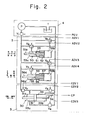
- FIG. 2 shows in greater detail the clutch actuator 3, the speed changing actuator assembly 5, and the hydraulic mechanism 4.
- the hydraulic mechanism 4 is composed of a tank T, a hydraulic pump P, and an on-off valve V 1 .
- the clutch actuator 3 comprises a cylinder assembly 30 composed of a cylinder 33, a piston 31 slidably disposed therein, and a piston rod 31a (3a in FIG. 1) having one end connected to the piston 31 and an opposite end to the release lever 2a of the clutch 2.
- the cylinder 33 has a fluid chamber 33a communicating with the pump P through an on-off valve V 2 and the on-off valve V 1 , and also with the tank T through an on-off valve V 3 and an on-off valve V 4 which is pulse-controlled.
- the cylinder 33 has another fluid chamber 33b communicating with the tank T at all times.
- a position sensor 34 detects an operated position of the piston rod 31a to thereby issue a signal indicative of the corresponding extent to which the clutch 2 is engaged.
- the gear changing actuator assembly 5 comprises a select actuator 50 and a shift actuator 55, which can selectively be stopped in three positions.
- the select actuator 50 is composed of a stepped cylinder 53, a first piston 51 slidably disposed in the stepped cylinder 53, and a second tubular piston 52 slidably disposed in the stepped cylinder 53 and fitted over the first piston 51.
- the shift actuator 55 is composed of a stepped cylinder 58, a first piston 56 slidably disposed in the stepped cylinder 58, and a second tubular piston 57 slidably disposed in the stepped cylinder 58 and fitted over the first piston 56.
- the first pistons 51, 56 of the select and shift actuators 50, 55 have piston rods 51a, 56a held in engagement with internal levers (not shown) in the gear transmission 6.
- the stepped cylinder 53 has fluid chambers 53a, 53b one on each side of the pistons 51, 52, and the stepped cylinder 58 has fluid chambers 58a, 58b one on each side of the pistons 56, 57.
- the actuators 50, 55 are in their neutral position as illustrated in FIG. 2.
- a hydraulic pressure acts in the fluid chambers 53a, 58a
- the first pistons 51, 56 and the second pistons 52, 57 are moved to the right (in FIG . 2 ).
- a hydraulic pressure acts in the fluid chambers 53b, 58b only the first pistons 51, 56 are moved to the left.
- the fluid chambers 53a, 53b in the select actuator 50 are held in communication through directional control valves V 5 , V 6 respectively with the pump P (via the on-off valve V I ) and the tank T.
- the fluid chambers 58a, 58b in the shift actuator 55 are held in communication through directional control valves V 7' V8 respectively with the pump P (via the on-off valve V 1 ) and the tank T.
- the gear transmission 6 is in a neutral position.
- the directional control valve V 7 is communicated to the pump P by a drive signal ADV 4 from the electronic control system 15 and the directional control valve V 8 is communicated to the tank T by a drive signal ADV 3
- the piston rod 56a is moved to the right to enable the gear transmission 6 to select a 4th gear position.
- the electronic control system 9 applies the drive signals ADV 3 , ADV 4 to communicate the directional control valves V 8 , v 7 with the pump P so that the shift actuator 55 is returned to the neutral position as shown.
- the electronic control system 9 issues a drive signal ADV 1 to communicate the directional control valve V 6 with the pump P and a drive signal ADV 2 to communicate the directional control valve V 5 with the tank T, thereby moving the piston rod 5 1a to the left to shift the select actuator 50 to a 5th-reverse select position.
- the electronic control system 9 thereafter applies the drive signal ADV 3 to communicate the directional control valve V 8 with the pump P and the drive signal ADV 4 to communicate the directional control valve V 7 with the tank T, thus shifting the shift actuator 55 to a 5th gear position whereupon the gear transmission 6 selects a 5th gear.
- the directional control valves V6, V5, V 8 , V 7 are operated respectively by the drive signals ADV 1 , ADV 2 .
- ADV 3 , ADV 4 from the electronic control system 9 to alternately actuate the select and shift actuators 50, 55 for enabling the gear transmission 6 to select desired gear positions.
- the shift map is stored as a table SM in the ROM 15b and is dependent on the car speed V and the accelerator ,for example as illustrated in Figure 3, pedal depression AP.
- the processor 9a relies on the shift map to determine an optimum gear position OPT dependent on the car speed V and the accelerator pedal depression AP.
- the processor 9a determines if it is possible to shift the gears to the optimum gear position OPT.
- the processor 9a reads a current gear position GP from the gear position sensor 6c through the input port 9d and compares the current gear position GP with the optimum gear position OPT. If the current gear position GP is different from the optimum gear position OPT, then the processor 9a decides that the gears can be shifted, and if not the processor 9a decides that the gears cannot be shifted.
- FIG. 5 illustrates a flowchart according to of progressive steps of gear changing operation the present invention, the steps being as follows:
- the retry monitoring times should preferably be determined dependent on if the water temperature WT is higher or lower than a preset water temperature WTo, and if the car speed V is higher or lower than a preset car speed for example Vo/as shown in the following Table:
- the processor 9a reads a timer area RETRY from the RAM 9e and compares the same with the retry monitoring times OVER1 through OVER3. If RETRY ⁇ OVER1, then the processor 9a decides that the time elapsed in shifting the gears to the optimum gear position OPT is within the first monitoring time OVER1, and the program goes to a step (i). If RETRY > OVER1, then the processor 9a decides that the time elapsed in shifting the gears to the optimum gear position OPT exceeds the first monitoring time, and compares the time elapsed with the second monitoring time OVER2.
- RETRY ⁇ OVER2, that is, RETRY is within the second monitoring time OVER2
- the processor 9a changes the valve drive pattern COM to a current gear position (optimum gear position prior to terminating the optimum (previous value of OPT) gear position OPT)/GP, and the program goes to step (i).
- the drive signal ADV for the current gear position GP is applied via the output port 9c to the gear changing actuator assembly 5, so that the gear changing operation is now directed from the optimum gear position OPT toward the current gear position (original position).
- RETRY > OVER2, that is, RETRY exceeds the second monitoring time OVER2 the processor 9a compares the time elapsed with the third monitoring time OVER3. If RETRY ⁇ OVER3, that is, RETRY is within the third monitoring time OVER3, then the processor 9a determines whether the current gear position GP in the RAM 9e is the neutral (N) position the current position GP is or not. If/the neutral position, then the processor goes to a step ( k), and if not, then the processor goes to a step (j).
- step (h) If RETRY > OVER3, that is, RETRY exceeds the third monitoring time OVER3, then the processor 9a decides that a series of retry steps is completed, and resets the content of the timer area RETRY to zero. The same step is also followed when the gear changing operation is started in step (d).
- the processor 9a compares the extent of engagement CLT of the clutch 2 stored in the RAM 9e with an extent of clutch engagement CLTo at the time the clutch 2 is disconnected. If CLT > CL T o, then the clutch is not disconnected (the clutch is connected incompletely), and therefore the clutch will be disconnected. If CLT ⁇ CLTo, the clutch is disconnected, and the solenoid-operated valves are energized according to the value of COM to operate the actuator assembly. "1" is added to the content of the timer area RETRY to update
- step (g) determines that the current gear position GP is not the neutral position
- step (g) determines that the current gear position GP is not the neutral position
- step (g) determines that the current gear position GP is not the neutral position
- step (g) determines that the current gear position GP is not the neutral position
- the valve drive pattern COM is returned to the optimum gear position OPT in the RAM 9e.
- the drive signal ADV corresponding to the optimum gear position O PT is applied through the output port 9c to the gear changing actuator assembly 5, and the gear changing operation is now directed back from the current gear position GP to the optimum gear position.
- the program thereafter goes to the step (i). the other hand,
- step (k) If on/ step (g) determines that the current gear position GP is the neutral position, then "1" is added to the content of the timer area RETRY to thereby renew the timer area RETRY and thereafter the clutch is connected. More specifically, when the position returned(to) between the first and second monitoring times is the neutral position, the clutch is connected between the second and third monitoring times. This reduces a load on synchronous-meshing, or alternatively the input shaft gear is driven by the engine through the clutch to vary the synchronous meshing phase to effect so-called double clutching which is effective in releasing a locked condition. After the clutch has been connected, the program goes back to step (b).
- the time measured by the timer retry is obtained by counting how many times the program loop is performed with the minimum unit of time equal to the microcomputer processing time - through to the point marked by from the step (a) / the connector (1) in the flowchart of FIG. 5.
- FIG. 4 shows control commands, varying with time, given by the microcomputer to the actuator.
- step (d) When it is detected that the optimum gear position OPT is different from the valve drive pattern COM, the is valve drive pattern COM/rewritten into the optimum gear position (step (d)).
- the timer area RETRY is reset to zero it is determined (step (h)). Then,/whether the clutch is disconnected . it is
- step (i) the solenoid-operated valves are energized according to the content of COM, and "1" is added to the timer area RETRY (step (i)) each time the program loop is performed until the gear changing operation to select the optimum gear position is completed.
- the first monitoring time OVER1 is exceeded, that is, the gear is in a case in which/not changed during the time OVER1, the operation is changed to restore the original gear position (step (f)).
- the timer area RETRY is renewed with the addition of "1”, and the clutch is kept disconnected (step (i)).
- the gear changing operation may be detected as being completed when the ratio of the numbers of r.p.m. of the input shaft 6 and the output shaft 6b coincides with the gear ratio of the optimum gear position.
- a method of controlling the gear changing operation in an automatic transmission having a gear transmission actuatable by a gear changing actuator assembly controlled by an electronic control system When operating the gear changing actuator assembly for a gear changing operation, an interval of time which elapses after the gear changing actuator aseembly is operated is measured with a timer, and the measured interval of time is compared with a preset interval of time. When a lock is detected as being caused at the time the gear changing operation is not completed within the preset interval of time, the gear changing actuator assembly is operated to a gear position different from a gear position (or a neutral position) which the gear changing actuator assembly has originally been operated to select.
Landscapes
- Engineering & Computer Science (AREA)
- Mechanical Engineering (AREA)
- General Engineering & Computer Science (AREA)
- Transportation (AREA)
- Chemical & Material Sciences (AREA)
- Combustion & Propulsion (AREA)
- Automation & Control Theory (AREA)
- Control Of Transmission Device (AREA)
Applications Claiming Priority (4)
| Application Number | Priority Date | Filing Date | Title |
|---|---|---|---|
| JP118451/83 | 1983-06-30 | ||
| JP118452/83 | 1983-06-30 | ||
| JP11845283A JPS6011760A (ja) | 1983-06-30 | 1983-06-30 | 自動変速機の変速制御法 |
| JP11845183A JPS6011759A (ja) | 1983-06-30 | 1983-06-30 | 自動変速機の変速制御法 |
Publications (2)
| Publication Number | Publication Date |
|---|---|
| EP0130812A1 true EP0130812A1 (de) | 1985-01-09 |
| EP0130812B1 EP0130812B1 (de) | 1987-11-04 |
Family
ID=26456387
Family Applications (1)
| Application Number | Title | Priority Date | Filing Date |
|---|---|---|---|
| EP84304443A Expired EP0130812B1 (de) | 1983-06-30 | 1984-06-29 | Vorrichtung zum Steuern des Gangwechsels in automatischen Getrieben |
Country Status (7)
| Country | Link |
|---|---|
| US (1) | US5043895A (de) |
| EP (1) | EP0130812B1 (de) |
| KR (1) | KR880002568B1 (de) |
| AU (1) | AU560057B2 (de) |
| CA (1) | CA1217834A (de) |
| DE (1) | DE3467226D1 (de) |
| ES (3) | ES8703978A1 (de) |
Cited By (12)
| Publication number | Priority date | Publication date | Assignee | Title |
|---|---|---|---|---|
| EP0209263A1 (de) * | 1985-07-15 | 1987-01-21 | A.B. Volvo | Kraftfahrzeuggetriebe |
| EP0217540A1 (de) * | 1985-08-29 | 1987-04-08 | Isuzu Motors Limited | Verfahren und Vorrichtung zum Steuern des Schaltvorganges bei automatischen Fahrzeuggetrieben |
| US4702127A (en) * | 1986-04-18 | 1987-10-27 | Eaton Corporation | Method for controlling AMT system including gear neutral sensor signal fault detection and tolerance |
| EP0161521B1 (de) * | 1984-04-18 | 1988-07-13 | Hitachi, Ltd. | Getriebesteuerung |
| US4846021A (en) * | 1986-02-17 | 1989-07-11 | Toyota Jidosha Kabushiki Kaisha | System for shift control in automatic transmission |
| EP0364220A3 (de) * | 1988-10-13 | 1991-03-27 | Eaton Corporation | Verfahren und Steuerungssystem zur Steuerung eines AMT-Systems unter Einschluss der Erkennung einer fehlerhaften Gang-Leerlaufanzeige |
| EP0350812A3 (de) * | 1988-07-15 | 1991-03-27 | Attila Dipl.-Ing. Madocsay | Vorrichtung zum automatischen Schalten mehrstufiger mechanischer Gangschaltungen von Kraftfahrzeugen |
| EP0602849A1 (de) * | 1992-12-18 | 1994-06-22 | Eaton Corporation | Verfahren zur Fehlerbeseitigung bei erfolglosen Schaltversuchen aus dem Leerlauf in automatischen oder halbautomatischen mechanischen Getriebesystemen |
| EP0628443A3 (de) * | 1993-06-10 | 1995-12-20 | Eaton Corp | Verfahren für eine Auskuppel-Steuerung. |
| EP0718142A3 (de) * | 1994-12-24 | 1996-08-07 | Massey Ferguson Sa | |
| EP0512727B1 (de) * | 1991-05-09 | 1996-09-04 | Eaton Corporation | Getriebezahn-Stoss/Surr-Steuerungsverfahren und -system |
| GB2311105A (en) * | 1996-03-14 | 1997-09-17 | Luk Getriebe Systeme Gmbh | Ensuring gear engagement in an automatically-controlled gearbox |
Families Citing this family (12)
| Publication number | Priority date | Publication date | Assignee | Title |
|---|---|---|---|---|
| US5401223A (en) * | 1993-08-18 | 1995-03-28 | Cummins Electronics Company, Inc. | Method and device for controlling critical switch failure and neutral conditions at high and low vehicle speeds |
| US5498195A (en) * | 1994-11-10 | 1996-03-12 | Cummins Electronics Company, Inc. | Apparatus and method for verifying gear engagement in controlling the automatic shifting of a manual-automatic transmission |
| US5638271A (en) * | 1995-01-04 | 1997-06-10 | Cummins Engine Company, Inc. | Apparatus and method for assisting gear engagement in controlling the automatic shifting of a manual-automatic transmission |
| US5653143A (en) * | 1995-06-06 | 1997-08-05 | Langevin; David W. | Automatic mechanical variable ratio transmission |
| US5609548A (en) * | 1995-06-07 | 1997-03-11 | Cummins Engine Company, Inc. | Apparatus and method for commanding a gear after an aborted shift attempt in controlling a manual-automatic transmission |
| US5591102A (en) * | 1995-06-07 | 1997-01-07 | Cummins Engine Company, Inc. | Apparatus and method for controlling a manual-automatic transmission after a power reset |
| JP3817297B2 (ja) * | 1996-04-17 | 2006-09-06 | ヴァレオユニシアトランスミッション株式会社 | 自動クラッチ |
| US6145398A (en) * | 1998-02-20 | 2000-11-14 | New Venture Gear, Inc. | Electronically controlled shift system for a manual transmission |
| DE19957917A1 (de) * | 1998-12-11 | 2000-06-15 | Luk Getriebe Systeme Gmbh | Betätigungseinrichtung |
| EP2902652A1 (de) * | 2012-09-26 | 2015-08-05 | Jatco Ltd | Automatikgetriebe und steuerungsverfahren für automatikgetriebe |
| JP5989882B2 (ja) * | 2015-10-13 | 2016-09-07 | ヤマハ発動機株式会社 | 変速装置、その変速装置を備えた車両、およびその変速装置を備えた自動二輪車 |
| CN107650791A (zh) * | 2017-09-28 | 2018-02-02 | 深圳市华琥技术有限公司 | 一种车辆监测系统及车辆 |
Citations (1)
| Publication number | Priority date | Publication date | Assignee | Title |
|---|---|---|---|---|
| GB2025546A (en) * | 1978-07-13 | 1980-01-23 | British Leyland Cars Ltd | Transmissions for motor vehicle |
Family Cites Families (15)
| Publication number | Priority date | Publication date | Assignee | Title |
|---|---|---|---|---|
| IT939884B (it) * | 1971-09-25 | 1973-02-10 | Fiat Spa | Cambio a sincronizzazione elettroni ca particolarmente per autoveicoli |
| FR2278520A1 (fr) * | 1974-04-24 | 1976-02-13 | Berliet Automobiles | Procede pour la commande automatique d'une boite de vitesses sur un vehicule automobile |
| GB1493191A (en) * | 1975-01-02 | 1977-11-23 | Texas Instruments Ltd | Controlled mechanical system |
| US4361060A (en) * | 1978-01-24 | 1982-11-30 | Smyth Robert Ralston | Mechanical automatic transmission |
| JPS5547041A (en) * | 1978-09-30 | 1980-04-02 | Aisin Warner Ltd | Controller for automatic speed change gear |
| FR2461857A1 (fr) * | 1979-07-24 | 1981-02-06 | Renault | Dispositif electronique de commande des changements de rapports de vitesses pour une transmission automatique de vehicule automobile |
| US4373619A (en) * | 1980-04-07 | 1983-02-15 | Grad-Line, Inc. | Transmission control system |
| JPS57146944A (en) * | 1981-03-04 | 1982-09-10 | Toyota Motor Corp | Speed change controller of automatic speed changer |
| JPS6049793B2 (ja) * | 1981-03-30 | 1985-11-05 | 日産自動車株式会社 | ロツクアツプ式自動変速機のロツクアツプ制御装置 |
| JPS57184751A (en) * | 1981-05-06 | 1982-11-13 | Toyota Motor Corp | Control system of automatic speed changer for vehicle |
| JPS6032063B2 (ja) * | 1981-07-21 | 1985-07-25 | トヨタ自動車株式会社 | 車輛用自動変速機の制御方法 |
| JPS5830555A (ja) * | 1981-07-21 | 1983-02-23 | Toyota Motor Corp | 車輛用自動変速機の制御方法 |
| JPS58118357A (ja) * | 1982-01-05 | 1983-07-14 | Mazda Motor Corp | 複合クラツチ式多段歯車変速機の変速制御方法および変速制御装置 |
| JPS58146748A (ja) * | 1982-02-22 | 1983-09-01 | Mazda Motor Corp | 複合クラッチ式多段歯車変速機の変速制御方法 |
| JPS5963230A (ja) * | 1982-10-04 | 1984-04-10 | Toyota Motor Corp | 車両の最適シフト時期表示装置 |
-
1984
- 1984-06-22 CA CA000457171A patent/CA1217834A/en not_active Expired
- 1984-06-26 AU AU29876/84A patent/AU560057B2/en not_active Ceased
- 1984-06-29 DE DE8484304443T patent/DE3467226D1/de not_active Expired
- 1984-06-29 ES ES545219A patent/ES8703978A1/es not_active Expired
- 1984-06-29 EP EP84304443A patent/EP0130812B1/de not_active Expired
- 1984-06-29 ES ES534150A patent/ES8604680A1/es not_active Expired
- 1984-06-30 KR KR1019840003772A patent/KR880002568B1/ko not_active Expired
-
1985
- 1985-07-01 ES ES545218A patent/ES8701336A1/es not_active Expired
-
1989
- 1989-07-05 US US07/374,551 patent/US5043895A/en not_active Expired - Fee Related
Patent Citations (1)
| Publication number | Priority date | Publication date | Assignee | Title |
|---|---|---|---|---|
| GB2025546A (en) * | 1978-07-13 | 1980-01-23 | British Leyland Cars Ltd | Transmissions for motor vehicle |
Cited By (14)
| Publication number | Priority date | Publication date | Assignee | Title |
|---|---|---|---|---|
| EP0161521B1 (de) * | 1984-04-18 | 1988-07-13 | Hitachi, Ltd. | Getriebesteuerung |
| EP0209263A1 (de) * | 1985-07-15 | 1987-01-21 | A.B. Volvo | Kraftfahrzeuggetriebe |
| EP0217540A1 (de) * | 1985-08-29 | 1987-04-08 | Isuzu Motors Limited | Verfahren und Vorrichtung zum Steuern des Schaltvorganges bei automatischen Fahrzeuggetrieben |
| US4766774A (en) * | 1985-08-29 | 1988-08-30 | Isuzu Motors Limited | Shift control method and apparatus for automatic transmissions used in automotive vehicles |
| US4846021A (en) * | 1986-02-17 | 1989-07-11 | Toyota Jidosha Kabushiki Kaisha | System for shift control in automatic transmission |
| US4702127A (en) * | 1986-04-18 | 1987-10-27 | Eaton Corporation | Method for controlling AMT system including gear neutral sensor signal fault detection and tolerance |
| EP0350812A3 (de) * | 1988-07-15 | 1991-03-27 | Attila Dipl.-Ing. Madocsay | Vorrichtung zum automatischen Schalten mehrstufiger mechanischer Gangschaltungen von Kraftfahrzeugen |
| EP0364220A3 (de) * | 1988-10-13 | 1991-03-27 | Eaton Corporation | Verfahren und Steuerungssystem zur Steuerung eines AMT-Systems unter Einschluss der Erkennung einer fehlerhaften Gang-Leerlaufanzeige |
| EP0512727B1 (de) * | 1991-05-09 | 1996-09-04 | Eaton Corporation | Getriebezahn-Stoss/Surr-Steuerungsverfahren und -system |
| EP0602849A1 (de) * | 1992-12-18 | 1994-06-22 | Eaton Corporation | Verfahren zur Fehlerbeseitigung bei erfolglosen Schaltversuchen aus dem Leerlauf in automatischen oder halbautomatischen mechanischen Getriebesystemen |
| EP0628443A3 (de) * | 1993-06-10 | 1995-12-20 | Eaton Corp | Verfahren für eine Auskuppel-Steuerung. |
| EP0718142A3 (de) * | 1994-12-24 | 1996-08-07 | Massey Ferguson Sa | |
| GB2311105A (en) * | 1996-03-14 | 1997-09-17 | Luk Getriebe Systeme Gmbh | Ensuring gear engagement in an automatically-controlled gearbox |
| GB2311105B (en) * | 1996-03-14 | 2000-07-19 | Luk Getriebe Systeme Gmbh | Automotive vehicle with automatically controlled transmission and torque transmitting system |
Also Published As
| Publication number | Publication date |
|---|---|
| ES8604680A1 (es) | 1986-02-01 |
| ES545219A0 (es) | 1987-03-01 |
| ES8701336A1 (es) | 1986-12-01 |
| CA1217834A (en) | 1987-02-10 |
| DE3467226D1 (en) | 1987-12-10 |
| KR850000621A (ko) | 1985-02-28 |
| AU2987684A (en) | 1985-01-03 |
| US5043895A (en) | 1991-08-27 |
| ES534150A0 (es) | 1986-02-01 |
| KR880002568B1 (ko) | 1988-11-30 |
| AU560057B2 (en) | 1987-03-26 |
| ES8703978A1 (es) | 1987-03-01 |
| ES545218A0 (es) | 1986-12-01 |
| EP0130812B1 (de) | 1987-11-04 |
Similar Documents
| Publication | Publication Date | Title |
|---|---|---|
| EP0130812B1 (de) | Vorrichtung zum Steuern des Gangwechsels in automatischen Getrieben | |
| EP0130792B1 (de) | Verfahren zur Steuerung des Startvorganges eines Fahrzeuges | |
| EP0130811A1 (de) | Verfahren zum Steuern des Gangwechsels in automatischen Getrieben | |
| US4677880A (en) | Method of controlling automatic transmission in accordance with engine operation | |
| US4638690A (en) | Method and apparatus for controlling electronically controlled transmissions | |
| EP0114513B1 (de) | Verfahren und Vorrichtung zum elektronischen Steuern eines Fahrzeugs | |
| US5029678A (en) | Automatic clutch control apparatus | |
| EP0170465A1 (de) | Halbautomatisches Getriebe mit Kraftverzweigung | |
| KR920008094B1 (ko) | 자동차변속기에 대한 출력속도센서 감지진단제어방법 | |
| KR100458056B1 (ko) | 자동변속기의오류감지방법 | |
| CA2129208C (en) | Clutch engagement control system in response to transmission shift lever position | |
| US5517411A (en) | Neutral attainment control system/method for controlling shifting in vehicular automated mechanical transmission systems | |
| EP0838002B1 (de) | Automatische bereichsschaltanordnung eines gangschaltgetriebes | |
| EP0410346A1 (de) | Kupplungssteuereinheit | |
| US20040014563A1 (en) | Transmission shift control with engine torque control | |
| GB2354296A (en) | Open-loop control of gearbox when fault occurs with vehicle at rest | |
| JPH0468172B2 (de) | ||
| JP3132358B2 (ja) | 自動変速機の制御装置 | |
| EP0410345B1 (de) | Automatisches Getriebe | |
| JPH0517984B2 (de) | ||
| JPH0465262B2 (de) | ||
| JPH0440215B2 (de) | ||
| JPS6011760A (ja) | 自動変速機の変速制御法 | |
| JPH0297731A (ja) | クラッチ制御装置の接続量学習装置 | |
| JPH0466733B2 (de) |
Legal Events
| Date | Code | Title | Description |
|---|---|---|---|
| PUAI | Public reference made under article 153(3) epc to a published international application that has entered the european phase |
Free format text: ORIGINAL CODE: 0009012 |
|
| AK | Designated contracting states |
Designated state(s): CH DE FR GB IT LI SE |
|
| 17P | Request for examination filed |
Effective date: 19850509 |
|
| 17Q | First examination report despatched |
Effective date: 19860306 |
|
| GRAA | (expected) grant |
Free format text: ORIGINAL CODE: 0009210 |
|
| AK | Designated contracting states |
Kind code of ref document: B1 Designated state(s): CH DE FR GB IT LI SE |
|
| REF | Corresponds to: |
Ref document number: 3467226 Country of ref document: DE Date of ref document: 19871210 |
|
| ITF | It: translation for a ep patent filed | ||
| ET | Fr: translation filed | ||
| PLBE | No opposition filed within time limit |
Free format text: ORIGINAL CODE: 0009261 |
|
| STAA | Information on the status of an ep patent application or granted ep patent |
Free format text: STATUS: NO OPPOSITION FILED WITHIN TIME LIMIT |
|
| 26N | No opposition filed | ||
| ITTA | It: last paid annual fee | ||
| EAL | Se: european patent in force in sweden |
Ref document number: 84304443.9 |
|
| PGFP | Annual fee paid to national office [announced via postgrant information from national office to epo] |
Ref country code: CH Payment date: 19950623 Year of fee payment: 12 |
|
| PG25 | Lapsed in a contracting state [announced via postgrant information from national office to epo] |
Ref country code: LI Effective date: 19960630 Ref country code: CH Effective date: 19960630 |
|
| REG | Reference to a national code |
Ref country code: CH Ref legal event code: PL |
|
| PGFP | Annual fee paid to national office [announced via postgrant information from national office to epo] |
Ref country code: SE Payment date: 20010517 Year of fee payment: 18 |
|
| REG | Reference to a national code |
Ref country code: GB Ref legal event code: IF02 |
|
| PG25 | Lapsed in a contracting state [announced via postgrant information from national office to epo] |
Ref country code: SE Free format text: LAPSE BECAUSE OF NON-PAYMENT OF DUE FEES Effective date: 20020630 |
|
| EUG | Se: european patent has lapsed | ||
| PGFP | Annual fee paid to national office [announced via postgrant information from national office to epo] |
Ref country code: FR Payment date: 20030512 Year of fee payment: 20 |
|
| PGFP | Annual fee paid to national office [announced via postgrant information from national office to epo] |
Ref country code: GB Payment date: 20030516 Year of fee payment: 20 |
|
| PGFP | Annual fee paid to national office [announced via postgrant information from national office to epo] |
Ref country code: DE Payment date: 20030527 Year of fee payment: 20 |
|
| PG25 | Lapsed in a contracting state [announced via postgrant information from national office to epo] |
Ref country code: GB Free format text: LAPSE BECAUSE OF EXPIRATION OF PROTECTION Effective date: 20040628 |
|
| REG | Reference to a national code |
Ref country code: GB Ref legal event code: PE20 |