EP0209263A1 - Kraftfahrzeuggetriebe - Google Patents
Kraftfahrzeuggetriebe Download PDFInfo
- Publication number
- EP0209263A1 EP0209263A1 EP86304796A EP86304796A EP0209263A1 EP 0209263 A1 EP0209263 A1 EP 0209263A1 EP 86304796 A EP86304796 A EP 86304796A EP 86304796 A EP86304796 A EP 86304796A EP 0209263 A1 EP0209263 A1 EP 0209263A1
- Authority
- EP
- European Patent Office
- Prior art keywords
- drive
- speed
- ratio
- vehicle
- engaged
- Prior art date
- Legal status (The legal status is an assumption and is not a legal conclusion. Google has not performed a legal analysis and makes no representation as to the accuracy of the status listed.)
- Granted
Links
Images

Classifications
-
- B—PERFORMING OPERATIONS; TRANSPORTING
- B60—VEHICLES IN GENERAL
- B60W—CONJOINT CONTROL OF VEHICLE SUB-UNITS OF DIFFERENT TYPE OR DIFFERENT FUNCTION; CONTROL SYSTEMS SPECIALLY ADAPTED FOR HYBRID VEHICLES; ROAD VEHICLE DRIVE CONTROL SYSTEMS FOR PURPOSES NOT RELATED TO THE CONTROL OF A PARTICULAR SUB-UNIT
- B60W30/00—Purposes of road vehicle drive control systems not related to the control of a particular sub-unit, e.g. of systems using conjoint control of vehicle sub-units
- B60W30/18—Propelling the vehicle
- B60W30/18009—Propelling the vehicle related to particular drive situations
- B60W30/18036—Reversing
- B60W30/18045—Rocking, i.e. fast change between forward and reverse
-
- F—MECHANICAL ENGINEERING; LIGHTING; HEATING; WEAPONS; BLASTING
- F16—ENGINEERING ELEMENTS AND UNITS; GENERAL MEASURES FOR PRODUCING AND MAINTAINING EFFECTIVE FUNCTIONING OF MACHINES OR INSTALLATIONS; THERMAL INSULATION IN GENERAL
- F16H—GEARING
- F16H61/00—Control functions within control units of change-speed- or reversing-gearings for conveying rotary motion ; Control of exclusively fluid gearing, friction gearing, gearings with endless flexible members or other particular types of gearing
- F16H61/02—Control functions within control units of change-speed- or reversing-gearings for conveying rotary motion ; Control of exclusively fluid gearing, friction gearing, gearings with endless flexible members or other particular types of gearing characterised by the signals used
- F16H61/0202—Control functions within control units of change-speed- or reversing-gearings for conveying rotary motion ; Control of exclusively fluid gearing, friction gearing, gearings with endless flexible members or other particular types of gearing characterised by the signals used the signals being electric
- F16H61/0204—Control functions within control units of change-speed- or reversing-gearings for conveying rotary motion ; Control of exclusively fluid gearing, friction gearing, gearings with endless flexible members or other particular types of gearing characterised by the signals used the signals being electric for gearshift control, e.g. control functions for performing shifting or generation of shift signal
- F16H61/0246—Control functions within control units of change-speed- or reversing-gearings for conveying rotary motion ; Control of exclusively fluid gearing, friction gearing, gearings with endless flexible members or other particular types of gearing characterised by the signals used the signals being electric for gearshift control, e.g. control functions for performing shifting or generation of shift signal characterised by initiating reverse gearshift
-
- F—MECHANICAL ENGINEERING; LIGHTING; HEATING; WEAPONS; BLASTING
- F16—ENGINEERING ELEMENTS AND UNITS; GENERAL MEASURES FOR PRODUCING AND MAINTAINING EFFECTIVE FUNCTIONING OF MACHINES OR INSTALLATIONS; THERMAL INSULATION IN GENERAL
- F16H—GEARING
- F16H2200/00—Transmissions for multiple ratios
- F16H2200/003—Transmissions for multiple ratios characterised by the number of forward speeds
- F16H2200/0047—Transmissions for multiple ratios characterised by the number of forward speeds the gear ratios comprising five forward speeds
-
- F—MECHANICAL ENGINEERING; LIGHTING; HEATING; WEAPONS; BLASTING
- F16—ENGINEERING ELEMENTS AND UNITS; GENERAL MEASURES FOR PRODUCING AND MAINTAINING EFFECTIVE FUNCTIONING OF MACHINES OR INSTALLATIONS; THERMAL INSULATION IN GENERAL
- F16H—GEARING
- F16H2200/00—Transmissions for multiple ratios
- F16H2200/0082—Transmissions for multiple ratios characterised by the number of reverse speeds
- F16H2200/0091—Transmissions for multiple ratios characterised by the number of reverse speeds the gear ratios comprising three reverse speeds
-
- F—MECHANICAL ENGINEERING; LIGHTING; HEATING; WEAPONS; BLASTING
- F16—ENGINEERING ELEMENTS AND UNITS; GENERAL MEASURES FOR PRODUCING AND MAINTAINING EFFECTIVE FUNCTIONING OF MACHINES OR INSTALLATIONS; THERMAL INSULATION IN GENERAL
- F16H—GEARING
- F16H2200/00—Transmissions for multiple ratios
- F16H2200/20—Transmissions using gears with orbital motion
- F16H2200/2002—Transmissions using gears with orbital motion characterised by the number of sets of orbital gears
- F16H2200/2012—Transmissions using gears with orbital motion characterised by the number of sets of orbital gears with four sets of orbital gears
-
- F—MECHANICAL ENGINEERING; LIGHTING; HEATING; WEAPONS; BLASTING
- F16—ENGINEERING ELEMENTS AND UNITS; GENERAL MEASURES FOR PRODUCING AND MAINTAINING EFFECTIVE FUNCTIONING OF MACHINES OR INSTALLATIONS; THERMAL INSULATION IN GENERAL
- F16H—GEARING
- F16H59/00—Control inputs to control units of change-speed- or reversing-gearings for conveying rotary motion
- F16H59/02—Selector apparatus
-
- F—MECHANICAL ENGINEERING; LIGHTING; HEATING; WEAPONS; BLASTING
- F16—ENGINEERING ELEMENTS AND UNITS; GENERAL MEASURES FOR PRODUCING AND MAINTAINING EFFECTIVE FUNCTIONING OF MACHINES OR INSTALLATIONS; THERMAL INSULATION IN GENERAL
- F16H—GEARING
- F16H61/00—Control functions within control units of change-speed- or reversing-gearings for conveying rotary motion ; Control of exclusively fluid gearing, friction gearing, gearings with endless flexible members or other particular types of gearing
- F16H61/02—Control functions within control units of change-speed- or reversing-gearings for conveying rotary motion ; Control of exclusively fluid gearing, friction gearing, gearings with endless flexible members or other particular types of gearing characterised by the signals used
- F16H61/0202—Control functions within control units of change-speed- or reversing-gearings for conveying rotary motion ; Control of exclusively fluid gearing, friction gearing, gearings with endless flexible members or other particular types of gearing characterised by the signals used the signals being electric
- F16H61/0204—Control functions within control units of change-speed- or reversing-gearings for conveying rotary motion ; Control of exclusively fluid gearing, friction gearing, gearings with endless flexible members or other particular types of gearing characterised by the signals used the signals being electric for gearshift control, e.g. control functions for performing shifting or generation of shift signal
- F16H61/0206—Layout of electro-hydraulic control circuits, e.g. arrangement of valves
-
- F—MECHANICAL ENGINEERING; LIGHTING; HEATING; WEAPONS; BLASTING
- F16—ENGINEERING ELEMENTS AND UNITS; GENERAL MEASURES FOR PRODUCING AND MAINTAINING EFFECTIVE FUNCTIONING OF MACHINES OR INSTALLATIONS; THERMAL INSULATION IN GENERAL
- F16H—GEARING
- F16H61/00—Control functions within control units of change-speed- or reversing-gearings for conveying rotary motion ; Control of exclusively fluid gearing, friction gearing, gearings with endless flexible members or other particular types of gearing
- F16H61/68—Control functions within control units of change-speed- or reversing-gearings for conveying rotary motion ; Control of exclusively fluid gearing, friction gearing, gearings with endless flexible members or other particular types of gearing specially adapted for stepped gearings
- F16H61/684—Control functions within control units of change-speed- or reversing-gearings for conveying rotary motion ; Control of exclusively fluid gearing, friction gearing, gearings with endless flexible members or other particular types of gearing specially adapted for stepped gearings without interruption of drive
- F16H61/686—Control functions within control units of change-speed- or reversing-gearings for conveying rotary motion ; Control of exclusively fluid gearing, friction gearing, gearings with endless flexible members or other particular types of gearing specially adapted for stepped gearings without interruption of drive with orbital gears
Definitions
- the present invention relates to vehicle power transmissions for work vehicles which frequently have to change their direction of movement.
- a vehicle is a wheeled loader having a bucket for collecting material such as sand or coal from a pile on the ground and transferring it into a larger vehicle or conveyor.
- Such a loader may only travel for a distance of five or ten metres before having to reverse its direction of movement, for example having collected a bucketful of material from the pile and moved backwards from the pile, it has to move forwards to transport the load in its bucket to the conveyor, then move backwards from the conveyor and thereafter forwards again to the pile.
- Suitable geared transmissions for use in such vehicles are disclosed in British Patent Specification No. 1597950.
- Swedish published Patent Specification 7905695-8 discloses a method of reversing such a vehicle while maintaining the engine running at normal speed and load and a suitable transmission control system for carrying out the method.
- the engine drives the wheels through a torque convertor and a gearbox. While moving in one direction, the driver can move a direction control lever (which may also control selection of some or all of the ratios) into a position corresponding to movement of the vehicle in the opposite direction.
- the working direction in the gearbox is reversed so that the torque transmitted from the engine through the torque convertor to the gearbox retards the vehicle until the latter is brought to rest and thereafter accelerates the vehicle in the opposite direction.
- An object of the present invention is to provide further improved retardation and thus faster change of direction without shock.
- a further object of the invention is to reduce the heat energy dissipated in the torque convertor and thus to obviate excessive rise of temperature therein, while still achieving the optimum rate of retardation.
- a transmission for a vehicle comprising a torque convertor to be driven by an internal combustion engine, and planetary change speed gearing having an input driven by the output of the torque convertor and an output connected to the driving wheels of the vehicle, the change-speed gearing'being of the kind in which the individual speed ratios in both a forward direction and a reverse direction of drive are each selectively engaged by the engagement of associated friction elements to provide a plurality of speed ratios in the forward direction and at least one speed ratio in the reverse direction and a driver-operated direction control element, characterised by control means responsive to movement of the control element from a first position corresponding to the prevailing direction of drive to a second position corresponding to the opposite direction of drive, to cause the following operations in sequence:-
- release 'of the friction element or elements determining the ratio engaged in the prevailing direction of drive, engagement of the friction element or elements associated with a high speed ratio in the opposite direction of drive and initiating engagement of the friction element or elements associated with a lower speed ratio in the said opposite direction of drive, followed by release of the friction element or elements associated with the said high ratio in the said opposite direction after a period of retardation of the vehicle but preferably before its speed has been reduced to zero in the said prevailing direction.
- the output of the torque convertor is forced to rotate counter to the direction of its input, thereby exerting retardation as in the case of the above-mentioned Swedish Patent Specification but at a lower value of retardation because the counter rotation is at a lower speed due to a relatively high ratio of the opposite direction being effective. Additional retardation is however exerted by the application (in slipping condition) of the friction element associated with the lower ratio of the opposite direction.
- the friction element of the high speed ratio of the opposite direction is released, the engine driving through the torque convertor completes the retardation to zero speed from the prevailing direction and then smoothly accelerates the vehicle in the lower speed ratio in the opposite direction.
- a further advantage of this arrangement is that the reduced speed of counter-rotation of the output of the torque convertor during the retardation results in less heat being generated in the torque convertor, thus obviating excessive temperature-rise therein, any loss of retardation exerted by the torque convertor being more than compensated by the additional retardation provided by the simultaneous application (in slipping condition) of the lower speed ratio in the opposite drive direction.
- the transmission shown in Figure 1 is driven by an internal combustion engine (not shown) having a shaft 10 which drives an input shaft 11 of change speed gearing through a torque converter 12 of conventional type having an impeller or pump element 12a, a reaction member 12b and a runner or turbine 12c connected to the shaft 11, the impeller 12a being fixed to the engine shaft 10.
- a torque converter 12 of conventional type having an impeller or pump element 12a, a reaction member 12b and a runner or turbine 12c connected to the shaft 11, the impeller 12a being fixed to the engine shaft 10.
- the shaft 11 forms an input to planetary gearing 13 of the kind shown in British Patent Specification No: 1597950, comprising four epicyclic gear trains 1, 2, 3 and 4, each consisting of a central sun gear C an internally toothed ring gear R and a set of planet pinions P meshing with both the central gear C and the ring gear R.
- the planet pinions P are rotatably mounted in planet carriers L.
- the central gears C3 and C4 are fixed to an output shaft 14 which is also secured to the planet carrier L2 and the ring gear Rl.
- the central gear C2 is driveable from the input shaft 11 by means of a pressure fluid operated forward clutch Kl.
- the central gear Cl can be driven from the shaft 11 through a further fluid pressure operated clutch K2 and can also be held stationary by means of a first brake BR1.
- the ring gears R2 and R3 and the planet carrier L1 are all interconnected and can be held stationary by a brake BR2.
- the planet carrier L3 is connected to the ring gear R4 and can be held stationary by a fluid pressure operated brake BR3.
- the planet carrier L4 can be held stationary by a fourth fluid pressure operating brake BR4.
- the output shaft 14 drives a pair of the vehicle wheels 15 through a gear 16 and a train 17 of idler gears meshing with the gear 18 on the shaft 14.
- all of the ring gears R have 84 teeth
- the central gear Cl has 48 teeth
- central gear C2 has 40 teeth
- the central gears C3 and C4 have 44 teeth.
- the brakes BRl, BR2, BR3 and BR4 are supplied with oil under pressure PK from a source 19 through non return valves V4, V3, V2 and V1 and solenoid operated valves S4, S3, S2 and S1 which are all collectively controlled by a control unit 20.
- the forward clutch Kl can be supplied with oil under pressure PI from a source 21 through a solenoid operated valve SF also controlled by the unit 20.
- the sources 19 and 21 for supplying the pressure Pk and P1 may be similar to those described in European Patent Specifitation No: 0040065.
- the clutch K2 can also be supplied with fluid under pressure from the source 21 through solenoid operated valves SR and S5 connected in series.
- the valve S5 In its unoperated state, the valve S5 connectes the downstream or outlet side of the reverse valve SR to the clutch K2.
- the valve S5 In its operated state, the valve S5 connectes the source 21 directly to the clutch K2.
- the fluid pressure in the forward clutch K1 is applied through a line 24 to one end of the spool of the reverse valve SR in the direction to retain it in its unoperated state.
- the pressure in the clutch K2 is applied through a line 25 to act on the spool of the valve S4 in a direction to retain the latter in its unoperated state.
- a directional control lever 26 conveniently mounted on the steering column and having a forward position F, a reverse position R and a neutral position N to control the driving direction of the transmission. Changes between the various ratios of either direction may be manually controlled by the driver, for example by arranging that the lever 26 may be twisted between positions 1, 2, 3 and A which respectively cause the control unit 20 to select intermediate ratios (if appropriate) or control the ratios automatically with the exception of the lowest ratio, particularly in the forward direction, which may be separately controllable by a 'kick-down' button 27 mounted adjacent or on the lever 26.
- the control unit causes changes between the forward ratios and between the reverse ratios in a conventional manner depending on sensed parameters such as engine speed, output speed and torque.
- the engine throttle is allowed to remain effectively open, so the engine speed remains substantially at its full working value throughout the sequence of operations associated with change of direction of the vehicle.
- control unit 20 can be programmed to change to the nearest ratio in the opposite direction when changing direction.
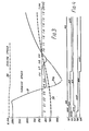
- the control unit 20 After the driver has moved the lever 26 from the reverse 'R' to the forward 'F' position, the control unit 20 first of all deenergizes the solenoid valve S2 and energizes the solenoid valve S5 at time 0 in Figures 3 and 4. This results in the brake BR3 being released and thus in a neutral condition in which only the clutch K2 is engaged. After 0.1 seconds, solenoid valves SF and S3 are energized in addition to the already energised solenoid valves SR and S5.
- the retardation of the vehicle is further increased as the result of energisation of the solenoid valve S3. This results in filling of the actuator cylinder of the brake BR2 followed by pressurisation of this brake actuator with consequent further absorption of the vehicle°s kinetic energy from its residual reverse motion.
- valves S5 and SR are released, in this case after 0.65 second.
- the transmission is now in its third forward ratio although still travelling slowly backwards and thus with relatively low counter rotation of the turbine.
- the considerable torque which is accordingly transmitted through the torque convertor completes the retardation to zero speed (hereafter 0.95 second) and thereafter smoothly accelerates the vehicle in the forward direction without shock.
- the line 31a indicates the turbine speed (in negative direction) which would occur if the clutch K2 were to be released at the instant when the forward clutch is engaged. Under such conditions, the variation in the turbine speed (to a relatively large negative value) could result in the generation of excessive heat in the torque convertor.
- the line 32 shows the output speed plotted against the time scale and the line 34 shows the very small variation in engine speed during the reversal process.
- the control system 20 may be arranged to perform similar operations when changing into third forward speed from first reverse speed (in which case the brake BR4 is initially released) and from third reverse speed (in which case the brake BR2 is initially released although subsequently re-engaged and a delay of 0.1 second is preferably introduced between engagement of the forward clutch Kl and initiation of re-engagement of the brake BR2).
- the clutch K2 should be released before the negative output speed falls to zero. To ensure that this happens, de-energisation of the valves SR and S5 should occur when the negative output speed has fallen to approximately 300 rpm.
- control lever 26 When the control lever 26 is moved from 'R' to 'N' and is allowed to remain in 'N' position for longer than the imposed delay period of approximately 0.5 second, its subsequent movement to 'F' position will result in the selected forward ratio being engaged directly unless the gearbox output speed exceeds 500 rpm, in which case the 5th forward ratio will be engaged directly.
Landscapes
- Engineering & Computer Science (AREA)
- General Engineering & Computer Science (AREA)
- Mechanical Engineering (AREA)
- Automation & Control Theory (AREA)
- Transportation (AREA)
- Control Of Transmission Device (AREA)
- Structure Of Transmissions (AREA)
Applications Claiming Priority (4)
| Application Number | Priority Date | Filing Date | Title |
|---|---|---|---|
| GB8517851 | 1985-07-15 | ||
| GB858517851A GB8517851D0 (en) | 1985-07-15 | 1985-07-15 | Vehicle power transmissions |
| GB8525245 | 1985-10-14 | ||
| GB8525245A GB2177764B (en) | 1985-07-15 | 1985-10-14 | Vehicle power transmissions |
Publications (2)
| Publication Number | Publication Date |
|---|---|
| EP0209263A1 true EP0209263A1 (de) | 1987-01-21 |
| EP0209263B1 EP0209263B1 (de) | 1990-08-01 |
Family
ID=26289534
Family Applications (1)
| Application Number | Title | Priority Date | Filing Date |
|---|---|---|---|
| EP86304796A Expired EP0209263B1 (de) | 1985-07-15 | 1986-06-23 | Kraftfahrzeuggetriebe |
Country Status (3)
| Country | Link |
|---|---|
| US (1) | US4724726A (de) |
| EP (1) | EP0209263B1 (de) |
| DE (1) | DE3673092D1 (de) |
Cited By (2)
| Publication number | Priority date | Publication date | Assignee | Title |
|---|---|---|---|---|
| EP0431677B1 (de) * | 1989-12-01 | 1996-07-03 | New Holland U.K. Limited | Wechselschaltungen in Lastschaltgetrieben |
| EP0573010B1 (de) * | 1992-06-04 | 1997-03-12 | Honda Giken Kogyo Kabushiki Kaisha | Steuerungseinrichtung für ein automatisches Kraftfahrzeuggetriebe |
Families Citing this family (7)
| Publication number | Priority date | Publication date | Assignee | Title |
|---|---|---|---|---|
| HU198778B (en) * | 1987-10-14 | 1989-11-28 | Csepeli Autogyar | Method for starting motor vehicle by back-and-forth running |
| US5080209A (en) * | 1990-10-15 | 1992-01-14 | General Electric Company | Manual override of an automatic ratio controller in a hydromechanical transmission |
| JPH05332424A (ja) * | 1992-06-03 | 1993-12-14 | Jatco Corp | 自動変速機の油圧制御装置 |
| JP3351823B2 (ja) * | 1992-09-10 | 2002-12-03 | 株式会社小松製作所 | 変速制御方法およびその装置 |
| DE4329918A1 (de) * | 1993-09-04 | 1995-03-09 | Bosch Gmbh Robert | Sicherheitssystem bei Kraftfahrzeugen mit Automatikgetriebe |
| JP3106297B2 (ja) * | 1996-09-25 | 2000-11-06 | 本田技研工業株式会社 | 車両用油圧作動式変速機の制御装置 |
| DE10250730A1 (de) * | 2001-12-08 | 2003-06-18 | Daimler Chrysler Ag | System mit einem Kraftfahrzeuggetriebe |
Citations (10)
| Publication number | Priority date | Publication date | Assignee | Title |
|---|---|---|---|---|
| GB1554215A (en) * | 1975-06-04 | 1979-10-17 | Renault | Hydraulic control arrangement for an automatic or semi automatic change-speed transmission |
| FR2454023A1 (fr) * | 1979-04-11 | 1980-11-07 | Clark Equipment Co | Dispositif de commande d'une transmission de vehicule |
| GB1597950A (en) * | 1976-12-22 | 1981-09-16 | Volvo Ab | Planetary gearing |
| GB1604932A (en) * | 1977-09-19 | 1981-12-16 | Bosch Gmbh Robert | Method and device for setting the operating force of gear parts in stepped gears |
| GB2085535A (en) * | 1979-06-28 | 1982-04-28 | Volvo Bm | Control system for controlling a power transmission device |
| US4361060A (en) * | 1978-01-24 | 1982-11-30 | Smyth Robert Ralston | Mechanical automatic transmission |
| EP0084235A2 (de) * | 1981-12-16 | 1983-07-27 | Eaton Corporation | Rückwärtsgangsteuerung mit Vorwahl |
| FR2548320A1 (fr) * | 1983-06-18 | 1985-01-04 | Renk Ag Zahnraeder | Installation de propulsion et de freinage pour vehicules |
| EP0130812A1 (de) * | 1983-06-30 | 1985-01-09 | Isuzu Motors Limited | Vorrichtung zum Steuern des Gangwechsels in automatischen Getrieben |
| EP0040065B1 (de) * | 1980-05-09 | 1986-02-19 | A.B. Volvo | Steuervorrichtung für mehrstufiges Getriebe |
Family Cites Families (12)
| Publication number | Priority date | Publication date | Assignee | Title |
|---|---|---|---|---|
| JPS4838574B1 (de) * | 1970-11-21 | 1973-11-19 | ||
| US3805640A (en) * | 1972-09-08 | 1974-04-23 | Twin Disc Inc | Electronically controlled power transmission |
| DE2700962C3 (de) * | 1977-01-12 | 1981-10-29 | Zahnradfabrik Friedrichshafen Ag, 7990 Friedrichshafen | Elektrohydraulische Gagnwechseleinrichutng eines lastschaltbaren Wechselgetriebes für Kraftfahrzeuge |
| DE2703009A1 (de) * | 1977-01-26 | 1978-07-27 | Bosch Gmbh Robert | Verfahren und vorrichtung zur reduzierung des schaltdrucks in kraftfahrzeugen |
| US4178518A (en) * | 1978-06-29 | 1979-12-11 | Caterpillar Tractor Co. | Electronic directional control circuit |
| CA1118235A (en) * | 1978-10-30 | 1982-02-16 | Albert A. Miller | Reatarding means for motor vehicles |
| US4346626A (en) * | 1978-12-27 | 1982-08-31 | Aisin-Warner K.K. | Control device for automatic transmission |
| US4425620A (en) * | 1981-01-28 | 1984-01-10 | Steiger Tractor, Inc. | Electrical control for power shift transmission |
| JPS5861349A (ja) * | 1981-10-06 | 1983-04-12 | Mitsubishi Motors Corp | 車両用自動変速機 |
| JPS59155649A (ja) * | 1983-02-21 | 1984-09-04 | Nissan Motor Co Ltd | 自動変速機の油圧制御装置 |
| JPS59183153A (ja) * | 1983-03-31 | 1984-10-18 | Aisin Seiki Co Ltd | 自動変速機の制御装置 |
| JPS604655A (ja) * | 1983-06-23 | 1985-01-11 | Nissan Motor Co Ltd | 自動変速機の油圧制御装置 |
-
1986
- 1986-06-23 EP EP86304796A patent/EP0209263B1/de not_active Expired
- 1986-06-23 DE DE8686304796T patent/DE3673092D1/de not_active Expired - Lifetime
- 1986-07-11 US US06/884,374 patent/US4724726A/en not_active Expired - Lifetime
Patent Citations (10)
| Publication number | Priority date | Publication date | Assignee | Title |
|---|---|---|---|---|
| GB1554215A (en) * | 1975-06-04 | 1979-10-17 | Renault | Hydraulic control arrangement for an automatic or semi automatic change-speed transmission |
| GB1597950A (en) * | 1976-12-22 | 1981-09-16 | Volvo Ab | Planetary gearing |
| GB1604932A (en) * | 1977-09-19 | 1981-12-16 | Bosch Gmbh Robert | Method and device for setting the operating force of gear parts in stepped gears |
| US4361060A (en) * | 1978-01-24 | 1982-11-30 | Smyth Robert Ralston | Mechanical automatic transmission |
| FR2454023A1 (fr) * | 1979-04-11 | 1980-11-07 | Clark Equipment Co | Dispositif de commande d'une transmission de vehicule |
| GB2085535A (en) * | 1979-06-28 | 1982-04-28 | Volvo Bm | Control system for controlling a power transmission device |
| EP0040065B1 (de) * | 1980-05-09 | 1986-02-19 | A.B. Volvo | Steuervorrichtung für mehrstufiges Getriebe |
| EP0084235A2 (de) * | 1981-12-16 | 1983-07-27 | Eaton Corporation | Rückwärtsgangsteuerung mit Vorwahl |
| FR2548320A1 (fr) * | 1983-06-18 | 1985-01-04 | Renk Ag Zahnraeder | Installation de propulsion et de freinage pour vehicules |
| EP0130812A1 (de) * | 1983-06-30 | 1985-01-09 | Isuzu Motors Limited | Vorrichtung zum Steuern des Gangwechsels in automatischen Getrieben |
Cited By (2)
| Publication number | Priority date | Publication date | Assignee | Title |
|---|---|---|---|---|
| EP0431677B1 (de) * | 1989-12-01 | 1996-07-03 | New Holland U.K. Limited | Wechselschaltungen in Lastschaltgetrieben |
| EP0573010B1 (de) * | 1992-06-04 | 1997-03-12 | Honda Giken Kogyo Kabushiki Kaisha | Steuerungseinrichtung für ein automatisches Kraftfahrzeuggetriebe |
Also Published As
| Publication number | Publication date |
|---|---|
| EP0209263B1 (de) | 1990-08-01 |
| US4724726A (en) | 1988-02-16 |
| DE3673092D1 (de) | 1990-09-06 |
Similar Documents
| Publication | Publication Date | Title |
|---|---|---|
| US4304150A (en) | Transmission unit for motor vehicles | |
| US4369671A (en) | Torque transfer mechanism with hydraulic control system for a four wheel drive vehicle | |
| US4224837A (en) | Four speed overdrive power transmission with bidirectional reaction brake band servo | |
| US3362245A (en) | Powershift transmission | |
| US4856369A (en) | Continually variable transmission having torque regeneration operating mode | |
| WO1994004848A1 (en) | Gear thrust controlled multi-mode clutch for power transmissions | |
| US5803858A (en) | Powertrain transmission with torque converter planetary gearing and a continuously variable transmission unit | |
| US4086827A (en) | Four-speed transmission | |
| EP0209263B1 (de) | Kraftfahrzeuggetriebe | |
| US4090415A (en) | Variable-speed planetary transmission | |
| US3282385A (en) | Device for controlling rate of engagement of hydraulic clutch | |
| US3090256A (en) | Transmission controls | |
| US3692160A (en) | Fluid power control system for vehicles | |
| GB2177764A (en) | Control of forward/reverse ratio in vehicle power transmissions | |
| US3731558A (en) | Line pressure regulating system for automatic power transmission | |
| US5092434A (en) | Control strategies for a dual range infinitely variable transmission | |
| JPH07208598A (ja) | 4速自動変速機用液圧制御システム | |
| JP2001280463A (ja) | 車両の自動変速装置 | |
| JPH09507908A (ja) | 自動車用自動変速システム | |
| GB1191388A (en) | Automatic Control Valve System for a Multiple Ratio Power Transmission Mechanism. | |
| US3055232A (en) | Transmission | |
| JPS62194067A (ja) | 変速機 | |
| JPH094706A (ja) | 自動変速機の変速制御装置 | |
| US2701480A (en) | Automatic transmission | |
| Nice | How automatic transmissions work |
Legal Events
| Date | Code | Title | Description |
|---|---|---|---|
| PUAI | Public reference made under article 153(3) epc to a published international application that has entered the european phase |
Free format text: ORIGINAL CODE: 0009012 |
|
| AK | Designated contracting states |
Kind code of ref document: A1 Designated state(s): DE FR IT SE |
|
| 17P | Request for examination filed |
Effective date: 19870708 |
|
| 17Q | First examination report despatched |
Effective date: 19881031 |
|
| ITF | It: translation for a ep patent filed | ||
| GRAA | (expected) grant |
Free format text: ORIGINAL CODE: 0009210 |
|
| AK | Designated contracting states |
Kind code of ref document: B1 Designated state(s): DE FR IT SE |
|
| REF | Corresponds to: |
Ref document number: 3673092 Country of ref document: DE Date of ref document: 19900906 |
|
| ET | Fr: translation filed | ||
| PLBE | No opposition filed within time limit |
Free format text: ORIGINAL CODE: 0009261 |
|
| STAA | Information on the status of an ep patent application or granted ep patent |
Free format text: STATUS: NO OPPOSITION FILED WITHIN TIME LIMIT |
|
| ITTA | It: last paid annual fee | ||
| 26N | No opposition filed | ||
| EAL | Se: european patent in force in sweden |
Ref document number: 86304796.5 |
|
| PGFP | Annual fee paid to national office [announced via postgrant information from national office to epo] |
Ref country code: SE Payment date: 20030604 Year of fee payment: 18 |
|
| PGFP | Annual fee paid to national office [announced via postgrant information from national office to epo] |
Ref country code: FR Payment date: 20030610 Year of fee payment: 18 |
|
| PGFP | Annual fee paid to national office [announced via postgrant information from national office to epo] |
Ref country code: DE Payment date: 20030707 Year of fee payment: 18 |
|
| PG25 | Lapsed in a contracting state [announced via postgrant information from national office to epo] |
Ref country code: SE Free format text: LAPSE BECAUSE OF NON-PAYMENT OF DUE FEES Effective date: 20040624 |
|
| PG25 | Lapsed in a contracting state [announced via postgrant information from national office to epo] |
Ref country code: DE Free format text: LAPSE BECAUSE OF NON-PAYMENT OF DUE FEES Effective date: 20050101 |
|
| EUG | Se: european patent has lapsed | ||
| EUG | Se: european patent has lapsed | ||
| PG25 | Lapsed in a contracting state [announced via postgrant information from national office to epo] |
Ref country code: FR Free format text: LAPSE BECAUSE OF NON-PAYMENT OF DUE FEES Effective date: 20050228 |
|
| REG | Reference to a national code |
Ref country code: FR Ref legal event code: ST |
|
| PG25 | Lapsed in a contracting state [announced via postgrant information from national office to epo] |
Ref country code: IT Free format text: LAPSE BECAUSE OF NON-PAYMENT OF DUE FEES;WARNING: LAPSES OF ITALIAN PATENTS WITH EFFECTIVE DATE BEFORE 2007 MAY HAVE OCCURRED AT ANY TIME BEFORE 2007. THE CORRECT EFFECTIVE DATE MAY BE DIFFERENT FROM THE ONE RECORDED. Effective date: 20050623 |