EP0130831A2 - Fokusdetektor eines optischen Systems - Google Patents
Fokusdetektor eines optischen Systems Download PDFInfo
- Publication number
- EP0130831A2 EP0130831A2 EP84304501A EP84304501A EP0130831A2 EP 0130831 A2 EP0130831 A2 EP 0130831A2 EP 84304501 A EP84304501 A EP 84304501A EP 84304501 A EP84304501 A EP 84304501A EP 0130831 A2 EP0130831 A2 EP 0130831A2
- Authority
- EP
- European Patent Office
- Prior art keywords
- focusing state
- detecting
- convergent lens
- optical system
- light beam
- Prior art date
- Legal status (The legal status is an assumption and is not a legal conclusion. Google has not performed a legal analysis and makes no representation as to the accuracy of the status listed.)
- Granted
Links
Images



Classifications
-
- G—PHYSICS
- G11—INFORMATION STORAGE
- G11B—INFORMATION STORAGE BASED ON RELATIVE MOVEMENT BETWEEN RECORD CARRIER AND TRANSDUCER
- G11B7/00—Recording or reproducing by optical means, e.g. recording using a thermal beam of optical radiation by modifying optical properties or the physical structure, reproducing using an optical beam at lower power by sensing optical properties; Record carriers therefor
- G11B7/08—Disposition or mounting of heads or light sources relatively to record carriers
- G11B7/09—Disposition or mounting of heads or light sources relatively to record carriers with provision for moving the light beam or focus plane for the purpose of maintaining alignment of the light beam relative to the record carrier during transducing operation, e.g. to compensate for surface irregularities of the latter or for track following
- G11B7/0908—Disposition or mounting of heads or light sources relatively to record carriers with provision for moving the light beam or focus plane for the purpose of maintaining alignment of the light beam relative to the record carrier during transducing operation, e.g. to compensate for surface irregularities of the latter or for track following for focusing only
- G11B7/0912—Disposition or mounting of heads or light sources relatively to record carriers with provision for moving the light beam or focus plane for the purpose of maintaining alignment of the light beam relative to the record carrier during transducing operation, e.g. to compensate for surface irregularities of the latter or for track following for focusing only by push-pull method
Definitions
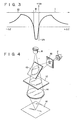
- a range I shows the level of the output signal from the differential amplifier in the case when the convergent lens is deviated from the position of the focusing state in a direction away from the optical disk.
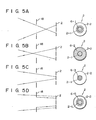
- the laser beam is in a focusing state as shown in Fig. 5A.
- a beam spot 6-1 having a size as shown in Fig. 5A produces a substantially uniform area on the photo sensitive regions 2-1 and 2-2 of the photodetector 2, photo signals Va and Vb of equal level are respectively generated from the first and second photo sensitive regions 2-1 and 2-2, and the level of the output signal Ve from the differential amplifier 4 is maintained at substantially zero.
- the convergent lens is deviated from the position of the focusing state in a direction away from the optical disk, the laser beam, diverged as compared with the laser beam shown in Fig.
- the size of the first and second photo sensitive regions 2-1, 2-2 of the photodetector 2 is determined so that the integrating value of the output signal, generated from the differential amplifier 4 while the convergent lens is moved from the position sufficiently separated from the optical disk to the position of the focusing state, becomes smaller than that of the output signal generated from the differential amplifier 4 while the convergent lens is moved sufficiently near the optical disk from the position of the focusing state. Since the photo sensitive regions 2-1, 2-2 respectively have specific sizes, the convergent lens 14 can be prevented from running away.
- the optical system is employed for detecting the state of the convergent lens by detecting the variation in the size of the beam spot on the photo sensitive regions of the photodetector 2.
- the system may not be limited to this particular detecting optical system, but other optical system such as an astigmatism optical system may be adopted.
- the photodetector 2 has the first and second photo sensitive regions 2-1 and 2-2 arranged concentrically.
- the photodetector shown in Fig. 8 may be designed to have the characteristics shown in Fig. 7.
- the aperture 18 may employ the type of rectangular shape shown in Fig. 9A or Fig.
- a plate 20 having an aperture 18 at a window 24, formed at the opening of a housing 22 containing the photodetector 2 may be extended, or the aperture 18 may be defined by a deposited layer deposited in the window 2.
- the positional relationship between the photodetector 2 and the aperture 18 is fixedly secured by providing the aperture 18 integrally with the housing 22, thereby eliminating the positional adjustment between both.
Landscapes
- Automatic Focus Adjustment (AREA)
- Optical Recording Or Reproduction (AREA)
Applications Claiming Priority (4)
| Application Number | Priority Date | Filing Date | Title |
|---|---|---|---|
| JP11934583A JPS6010423A (ja) | 1983-06-30 | 1983-06-30 | 焦点位置誤差検出装置 |
| JP119345/83 | 1983-06-30 | ||
| JP228337/83 | 1983-12-05 | ||
| JP22833783A JPS60121536A (ja) | 1983-12-05 | 1983-12-05 | 焦点位置制御方法 |
Publications (3)
| Publication Number | Publication Date |
|---|---|
| EP0130831A2 true EP0130831A2 (de) | 1985-01-09 |
| EP0130831A3 EP0130831A3 (en) | 1985-06-26 |
| EP0130831B1 EP0130831B1 (de) | 1989-09-27 |
Family
ID=26457112
Family Applications (1)
| Application Number | Title | Priority Date | Filing Date |
|---|---|---|---|
| EP84304501A Expired EP0130831B1 (de) | 1983-06-30 | 1984-06-29 | Fokusdetektor eines optischen Systems |
Country Status (3)
| Country | Link |
|---|---|
| US (1) | US4705941A (de) |
| EP (1) | EP0130831B1 (de) |
| DE (1) | DE3479935D1 (de) |
Cited By (7)
| Publication number | Priority date | Publication date | Assignee | Title |
|---|---|---|---|---|
| EP0248479A1 (de) * | 1986-06-04 | 1987-12-09 | Koninklijke Philips Electronics N.V. | Optische Messanordnung des Abstands zwischen einer Oberfläche und einer Bezugsebene |
| EP0170381A3 (en) * | 1984-06-22 | 1987-12-23 | Fuji Photo Film Co., Ltd. | Focussing error detection device for use in optical disk type recording system |
| DE3913229A1 (de) * | 1988-09-19 | 1990-03-22 | Pioneer Electronic Corp | Wiedergabegeraet fuer optische informationen |
| DE4006286A1 (de) * | 1989-06-19 | 1990-12-20 | Pioneer Electronic Corp | Optische informationswiedergabevorrichtung |
| EP0372365A3 (de) * | 1988-12-09 | 1991-05-29 | Sharp Kabushiki Kaisha | Optische Abtastvorrichtung |
| US5172366A (en) * | 1988-09-19 | 1992-12-15 | Pioneer Electronic Corporation | Optical information reproducing apparatus with selective photodetector output |
| EP0532246A3 (de) * | 1991-09-11 | 1993-04-21 | International Business Machines Corporation | Linsenfokussierverfahren und -mittel |
Families Citing this family (5)
| Publication number | Priority date | Publication date | Assignee | Title |
|---|---|---|---|---|
| US5231621A (en) * | 1986-09-05 | 1993-07-27 | Canon Kabushiki Kaisha | Focus detector which serves to split off a portion of a detected light beam only when the detected light beam is not refocused at an expected refocus point |
| JPS63257925A (ja) * | 1987-04-15 | 1988-10-25 | Nippon Coinco:Kk | 光ヘツドの焦点制御信号検出装置 |
| WO1992006359A1 (en) * | 1990-10-09 | 1992-04-16 | Metronics, Inc. | Laser autofocus apparatus and method |
| DE102015013913A1 (de) | 2015-10-27 | 2017-04-27 | Deutsch Französisches Forschungsinstitut Saint Louis | Vollkalibriges, drallstabilisiertes Lenkgeschoss mit einer hohen Reichweite |
| CN107560713A (zh) * | 2017-10-27 | 2018-01-09 | 罗沛棋 | 基于渐变透过率滤镜的振动信号提取装置 |
Family Cites Families (6)
| Publication number | Priority date | Publication date | Assignee | Title |
|---|---|---|---|---|
| GB1603596A (en) * | 1977-06-06 | 1981-11-25 | Mca Disco Vision | Optical transducer and focusing system |
| JPS5644126A (en) * | 1979-09-19 | 1981-04-23 | Sony Corp | Optical signal head |
| US4370551A (en) * | 1980-03-18 | 1983-01-25 | Nippon Kogaku K.K. | Focus detecting device |
| US4357533A (en) * | 1980-07-14 | 1982-11-02 | Discovision Associates | Focus detector for an optical disc playback system |
| JPS57135326A (en) * | 1981-02-16 | 1982-08-20 | Nec Corp | Photodetecting device |
| US4521680A (en) * | 1981-07-20 | 1985-06-04 | Tokyo Shibaura Denki Kabushiki Kaisha | System for focusing a light beam on a light reflecting surface |
-
1984
- 1984-06-28 US US06/625,609 patent/US4705941A/en not_active Expired - Lifetime
- 1984-06-29 DE DE8484304501T patent/DE3479935D1/de not_active Expired
- 1984-06-29 EP EP84304501A patent/EP0130831B1/de not_active Expired
Cited By (8)
| Publication number | Priority date | Publication date | Assignee | Title |
|---|---|---|---|---|
| EP0170381A3 (en) * | 1984-06-22 | 1987-12-23 | Fuji Photo Film Co., Ltd. | Focussing error detection device for use in optical disk type recording system |
| EP0248479A1 (de) * | 1986-06-04 | 1987-12-09 | Koninklijke Philips Electronics N.V. | Optische Messanordnung des Abstands zwischen einer Oberfläche und einer Bezugsebene |
| US4874246A (en) * | 1986-06-04 | 1989-10-17 | U.S. Philips Corp. | Arrangement for optically measuring a distance between a surface and a reference plane |
| DE3913229A1 (de) * | 1988-09-19 | 1990-03-22 | Pioneer Electronic Corp | Wiedergabegeraet fuer optische informationen |
| US5172366A (en) * | 1988-09-19 | 1992-12-15 | Pioneer Electronic Corporation | Optical information reproducing apparatus with selective photodetector output |
| EP0372365A3 (de) * | 1988-12-09 | 1991-05-29 | Sharp Kabushiki Kaisha | Optische Abtastvorrichtung |
| DE4006286A1 (de) * | 1989-06-19 | 1990-12-20 | Pioneer Electronic Corp | Optische informationswiedergabevorrichtung |
| EP0532246A3 (de) * | 1991-09-11 | 1993-04-21 | International Business Machines Corporation | Linsenfokussierverfahren und -mittel |
Also Published As
| Publication number | Publication date |
|---|---|
| US4705941A (en) | 1987-11-10 |
| EP0130831B1 (de) | 1989-09-27 |
| DE3479935D1 (en) | 1989-11-02 |
| EP0130831A3 (en) | 1985-06-26 |
Similar Documents
| Publication | Publication Date | Title |
|---|---|---|
| US4705941A (en) | Apparatus for detecting a focusing state of an optical system | |
| EP0070552A2 (de) | Optischer Kopf | |
| US4767921A (en) | Optical pickup device wherein the astigmatic converged beam spot is aligned along the dividing lines of the four-division photo-detector | |
| US6114689A (en) | Optical pickup device | |
| US5745465A (en) | Digital video disc pick-up head system | |
| US4672188A (en) | Focus detector for optical apparatus | |
| US4654515A (en) | Optical head for focussing a light beam on an information recording medium | |
| US5357102A (en) | Tilted light detection device for preventing undesirable retro-reflection | |
| US4654516A (en) | Optical head | |
| US4847480A (en) | Focus error detecting apparatus | |
| KR940012274A (ko) | 광픽업 장치 | |
| JPS5845629A (ja) | 焦点誤差信号検出機能を備えた集光装置 | |
| JPS58208945A (ja) | 焦点検出方法および装置 | |
| JPH076380A (ja) | 光ヘッド | |
| KR0134842B1 (ko) | 재생전용 광픽업 광학계 | |
| JPS6020322A (ja) | 光デイスクピツクアツプ装置 | |
| JPS649656B2 (de) | ||
| JPS59157852A (ja) | 光学ヘツド | |
| JPS6371939A (ja) | 光学ヘッド | |
| JPH0329121A (ja) | 光学ヘッド | |
| JPS598146A (ja) | 光ピツクアツプの焦点検出装置 | |
| JPS627610B2 (de) | ||
| JPS62275326A (ja) | 自動焦点合わせ方式 | |
| JPH0424768B2 (de) | ||
| JPH025230A (ja) | 光学式情報再生装置 |
Legal Events
| Date | Code | Title | Description |
|---|---|---|---|
| PUAI | Public reference made under article 153(3) epc to a published international application that has entered the european phase |
Free format text: ORIGINAL CODE: 0009012 |
|
| 17P | Request for examination filed |
Effective date: 19840711 |
|
| AK | Designated contracting states |
Designated state(s): DE FR GB NL |
|
| PUAL | Search report despatched |
Free format text: ORIGINAL CODE: 0009013 |
|
| AK | Designated contracting states |
Designated state(s): DE FR GB NL |
|
| 17Q | First examination report despatched |
Effective date: 19861217 |
|
| GRAA | (expected) grant |
Free format text: ORIGINAL CODE: 0009210 |
|
| AK | Designated contracting states |
Kind code of ref document: B1 Designated state(s): DE FR GB NL |
|
| REF | Corresponds to: |
Ref document number: 3479935 Country of ref document: DE Date of ref document: 19891102 |
|
| ET | Fr: translation filed | ||
| PLBE | No opposition filed within time limit |
Free format text: ORIGINAL CODE: 0009261 |
|
| STAA | Information on the status of an ep patent application or granted ep patent |
Free format text: STATUS: NO OPPOSITION FILED WITHIN TIME LIMIT |
|
| 26N | No opposition filed | ||
| REG | Reference to a national code |
Ref country code: GB Ref legal event code: 746 Effective date: 19981010 |
|
| REG | Reference to a national code |
Ref country code: FR Ref legal event code: D6 |
|
| PGFP | Annual fee paid to national office [announced via postgrant information from national office to epo] |
Ref country code: FR Payment date: 19990610 Year of fee payment: 16 |
|
| PGFP | Annual fee paid to national office [announced via postgrant information from national office to epo] |
Ref country code: GB Payment date: 19990623 Year of fee payment: 16 |
|
| PGFP | Annual fee paid to national office [announced via postgrant information from national office to epo] |
Ref country code: NL Payment date: 19990628 Year of fee payment: 16 |
|
| PGFP | Annual fee paid to national office [announced via postgrant information from national office to epo] |
Ref country code: DE Payment date: 19990706 Year of fee payment: 16 |
|
| PG25 | Lapsed in a contracting state [announced via postgrant information from national office to epo] |
Ref country code: GB Free format text: LAPSE BECAUSE OF NON-PAYMENT OF DUE FEES Effective date: 20000629 |
|
| PG25 | Lapsed in a contracting state [announced via postgrant information from national office to epo] |
Ref country code: NL Free format text: LAPSE BECAUSE OF NON-PAYMENT OF DUE FEES Effective date: 20010101 |
|
| GBPC | Gb: european patent ceased through non-payment of renewal fee |
Effective date: 20000629 |
|
| PG25 | Lapsed in a contracting state [announced via postgrant information from national office to epo] |
Ref country code: FR Free format text: LAPSE BECAUSE OF NON-PAYMENT OF DUE FEES Effective date: 20010228 |
|
| NLV4 | Nl: lapsed or anulled due to non-payment of the annual fee |
Effective date: 20010101 |
|
| REG | Reference to a national code |
Ref country code: FR Ref legal event code: ST |
|
| PG25 | Lapsed in a contracting state [announced via postgrant information from national office to epo] |
Ref country code: DE Free format text: LAPSE BECAUSE OF NON-PAYMENT OF DUE FEES Effective date: 20010403 |