EP0131275A2 - Porte, en particulier porte de garage - Google Patents
Porte, en particulier porte de garage Download PDFInfo
- Publication number
- EP0131275A2 EP0131275A2 EP84107906A EP84107906A EP0131275A2 EP 0131275 A2 EP0131275 A2 EP 0131275A2 EP 84107906 A EP84107906 A EP 84107906A EP 84107906 A EP84107906 A EP 84107906A EP 0131275 A2 EP0131275 A2 EP 0131275A2
- Authority
- EP
- European Patent Office
- Prior art keywords
- gate
- gate according
- wing
- leaf
- driver
- Prior art date
- Legal status (The legal status is an assumption and is not a legal conclusion. Google has not performed a legal analysis and makes no representation as to the accuracy of the status listed.)
- Withdrawn
Links
- 230000008878 coupling Effects 0.000 claims description 10
- 238000010168 coupling process Methods 0.000 claims description 10
- 238000005859 coupling reaction Methods 0.000 claims description 10
- 238000000034 method Methods 0.000 claims description 5
- 230000008569 process Effects 0.000 claims description 5
- 238000009434 installation Methods 0.000 description 4
- 230000002349 favourable effect Effects 0.000 description 3
- 230000001133 acceleration Effects 0.000 description 2
- 230000009471 action Effects 0.000 description 1
- 230000008901 benefit Effects 0.000 description 1
- 230000015572 biosynthetic process Effects 0.000 description 1
- 238000010276 construction Methods 0.000 description 1
- 230000000694 effects Effects 0.000 description 1
- 230000007246 mechanism Effects 0.000 description 1
- 238000011084 recovery Methods 0.000 description 1
- 238000009420 retrofitting Methods 0.000 description 1
- 238000009827 uniform distribution Methods 0.000 description 1
Images

Classifications
-
- E—FIXED CONSTRUCTIONS
- E05—LOCKS; KEYS; WINDOW OR DOOR FITTINGS; SAFES
- E05D—HINGES OR SUSPENSION DEVICES FOR DOORS, WINDOWS OR WINGS
- E05D15/00—Suspension arrangements for wings
- E05D15/36—Suspension arrangements for wings moving along slide-ways so arranged that one guide-member of the wing moves in a direction substantially perpendicular to the movement of another guide member
- E05D15/38—Suspension arrangements for wings moving along slide-ways so arranged that one guide-member of the wing moves in a direction substantially perpendicular to the movement of another guide member for upwardly-moving wings, e.g. up-and-over doors
-
- E—FIXED CONSTRUCTIONS
- E05—LOCKS; KEYS; WINDOW OR DOOR FITTINGS; SAFES
- E05F—DEVICES FOR MOVING WINGS INTO OPEN OR CLOSED POSITION; CHECKS FOR WINGS; WING FITTINGS NOT OTHERWISE PROVIDED FOR, CONCERNED WITH THE FUNCTIONING OF THE WING
- E05F15/00—Power-operated mechanisms for wings
- E05F15/60—Power-operated mechanisms for wings using electrical actuators
- E05F15/603—Power-operated mechanisms for wings using electrical actuators using rotary electromotors
- E05F15/665—Power-operated mechanisms for wings using electrical actuators using rotary electromotors for vertically-sliding wings
- E05F15/668—Power-operated mechanisms for wings using electrical actuators using rotary electromotors for vertically-sliding wings for overhead wings
- E05F15/681—Power-operated mechanisms for wings using electrical actuators using rotary electromotors for vertically-sliding wings for overhead wings operated by flexible elongated pulling elements, e.g. belts
- E05F15/686—Power-operated mechanisms for wings using electrical actuators using rotary electromotors for vertically-sliding wings for overhead wings operated by flexible elongated pulling elements, e.g. belts by cables or ropes
-
- E—FIXED CONSTRUCTIONS
- E05—LOCKS; KEYS; WINDOW OR DOOR FITTINGS; SAFES
- E05Y—INDEXING SCHEME ASSOCIATED WITH SUBCLASSES E05D AND E05F, RELATING TO CONSTRUCTION ELEMENTS, ELECTRIC CONTROL, POWER SUPPLY, POWER SIGNAL OR TRANSMISSION, USER INTERFACES, MOUNTING OR COUPLING, DETAILS, ACCESSORIES, AUXILIARY OPERATIONS NOT OTHERWISE PROVIDED FOR, APPLICATION THEREOF
- E05Y2900/00—Application of doors, windows, wings or fittings thereof
- E05Y2900/10—Application of doors, windows, wings or fittings thereof for buildings or parts thereof
- E05Y2900/106—Application of doors, windows, wings or fittings thereof for buildings or parts thereof for garages
Definitions
- the present invention relates to a door, in particular garage door, mi + a tilting leaf, which from its approximately vertical-closed position to an e + wa horizontal overhead -Offen position be brought is + by the leaf in the upper region with a force on the Gate wing is connected in an approximately horizontal direction transmitting means.
- Kipp + ore is usually used with vertical guideways attached to the outer frame, into which pins attached at the bottom of the gate wing engage.
- the chain drive commonly used with handlebar-spring tilt gates can only generate horizontal thrust forces, which the pins e.g. would slide against the vertical guide rails when closing the gate.
- This object is achieved in that a further means is provided which exerts a force on the gate wing in an approximately vertical plane.
- a simple design of the vertically acting means results from the fact that the further means is designed as a pull rope.
- the first means comprises an electromotive chain with at least one driver connected to the gate wing in the upper region
- the pull cable is attached to the driver, which is connected to the lower part of the gate wing via deflection rollers connected is. This ensures that the rope connected to the existing operator of the chain drive pulls the gate leaf from its overhead open position into the closed position. The opening movement takes over + the chain drive directly.
- the length compensator can be designed as a spring-supported pull bottle, which on the one hand enables inexpensive and on the other hand a safe length compensation.
- the length compensator can be easily stored on a guide rail of the chain frame to save space. It therefore fits into a space that is always available.
- the traction cable is also accommodated in a space-saving manner in that it is guided to the deflection rollers via a roller of the length compensator.
- a deflection roller is attached to the lower vertical part of the outer frame and a further deflection roller at the top in the area of the corner.
- a 'coupling is attached to the gate wing in the upper region, which is connected to the driver with an access such that the coupling is dragged by the driver during the opening process, while it detaches from the driver during the closing process. This allows the driver to run ahead of the paddock during the closing process.
- the coupling can be easily carried out with an eyelet on the pull rope.
- the traction means transmitting the closing forces are divided into those acting on the left and right sides.
- the traction means acting on the left and right sides are connected to one another via a balance beam.
- a continuous traction device is to be used instead of a drive with a rotating chain, it is advantageous that the traction device is attached to the top of the gate +, runs over a drive pulley, via deflection - roll connected to the gate wing below and equipped with one or more length compensators.
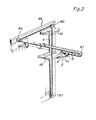
- the gate leaf 15 is drawn in the half-open position. It is guided vertically through the guideways 2 mi attached to the outer frame + the pin 12, which are attached to the gate leaf 15.
- the horizontal guideways 16 and the supporting rollers 17 running therein effect the horizontal guidance and support the gate wing.
- the compensating for the sash weight is carried out by the compensating weights 18 which hang on the guide pins 12 via the cable pulls 19.
- the drive consists of a chain 1 running approximately horizontally above the swivel space, which is driven by an electric motor. With the chain drive 1, a driver 5 is moved horizontally, dragging a coupling 3 when opening, which is articulated to the gate wing.
- a traction rope 4 hangs on the driver and is guided over the rope pulleys 61, 83, 82, 81 to the lower part of the gate leaf 15 and fastened there.
- the spring-supported length adjuster 6 with its pulley 61 is attached to the guide rail 7 of the chain frame, keeps the pull cable 4 under tension and enables the cable length to be compensated.
- the driver 5 transported by the drive chain + tows the coupling 3 and thus pulls + the gate leaf 15 into its overhead open position.
- the counterweights 18 are usually somewhat oversized so that the gate wing reaches its end position safely in the last movement phase and remains there non-positively.
- the length compensator 6 holds the pull rope 4, which is not used when opening, with a slight tension.
- a resilient element + 11 can be provided to reduce acceleration quantities.
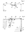
- Fig. 3 From Fig. 3 the formation of a double-acting cable 4 can be seen, which is provided for wide gates or for gates with torsionally soft wings.
- the balance beam 13 balances the forces and the length + olerances.
- Fig. 4 shows an embodiment with continuous traction means 43, in which the traction means 43 is driven directly instead of the rotating chain.
- the traction means 43 is guided from the gate leaf 21 below via the pulleys 81, 82, 83 and a drive pulley 14 to the gate leaf 20 above.
- the length compensation and the rope tension are preferably provided by 2 length compensators 62 and 63, which in the exemplary embodiment are designed as tension spring-tensioned bottles.
- the traction means 43 running through can also be divided into rope and chain sections.
- the chain section is provided in the engagement area of the drive pulley 14, which in this case consists of a chain wheel.
- the invention is not limited to the exemplary embodiments shown here. It is possible, for example, to install the drive motor elsewhere or to save a deflection roller, the traction cable running directly from the bottle 61 to the pulley 82.
- the eyelet 9 can also be guided through the guide rail 7 instead of through the pull rope.
Landscapes
- Engineering & Computer Science (AREA)
- Mechanical Engineering (AREA)
- Power-Operated Mechanisms For Wings (AREA)
- Barrages (AREA)
Applications Claiming Priority (2)
| Application Number | Priority Date | Filing Date | Title |
|---|---|---|---|
| DE3324837 | 1983-07-09 | ||
| DE19833324837 DE3324837A1 (de) | 1983-07-09 | 1983-07-09 | Antrieb fuer kippbare tore |
Publications (2)
| Publication Number | Publication Date |
|---|---|
| EP0131275A2 true EP0131275A2 (fr) | 1985-01-16 |
| EP0131275A3 EP0131275A3 (fr) | 1985-07-03 |
Family
ID=6203596
Family Applications (1)
| Application Number | Title | Priority Date | Filing Date |
|---|---|---|---|
| EP84107906A Withdrawn EP0131275A3 (fr) | 1983-07-09 | 1984-07-06 | Porte, en particulier porte de garage |
Country Status (2)
| Country | Link |
|---|---|
| EP (1) | EP0131275A3 (fr) |
| DE (1) | DE3324837A1 (fr) |
Cited By (2)
| Publication number | Priority date | Publication date | Assignee | Title |
|---|---|---|---|---|
| LU92714B1 (fr) * | 2015-05-11 | 2016-11-14 | Pega Sa | Porte basculante |
| EP3181789A1 (fr) * | 2015-12-16 | 2017-06-21 | Belu Verwaltungsgesellschaft mbH | Porte motorisée |
Families Citing this family (1)
| Publication number | Priority date | Publication date | Assignee | Title |
|---|---|---|---|---|
| DE8715917U1 (de) * | 1987-12-02 | 1988-04-28 | Müller, Günter, 5418 Goddert | Schwingtor, insbesondere für Garagen |
Family Cites Families (2)
| Publication number | Priority date | Publication date | Assignee | Title |
|---|---|---|---|---|
| FR1575561A (fr) * | 1968-01-24 | 1969-07-25 | ||
| FR2105464A5 (fr) * | 1970-09-08 | 1972-04-28 | Tubauto |
-
1983
- 1983-07-09 DE DE19833324837 patent/DE3324837A1/de not_active Withdrawn
-
1984
- 1984-07-06 EP EP84107906A patent/EP0131275A3/fr not_active Withdrawn
Cited By (3)
| Publication number | Priority date | Publication date | Assignee | Title |
|---|---|---|---|---|
| LU92714B1 (fr) * | 2015-05-11 | 2016-11-14 | Pega Sa | Porte basculante |
| WO2016180877A1 (fr) * | 2015-05-11 | 2016-11-17 | Pega, Société Anonyme | Porte basculante |
| EP3181789A1 (fr) * | 2015-12-16 | 2017-06-21 | Belu Verwaltungsgesellschaft mbH | Porte motorisée |
Also Published As
| Publication number | Publication date |
|---|---|
| DE3324837A1 (de) | 1985-01-17 |
| EP0131275A3 (fr) | 1985-07-03 |
Similar Documents
| Publication | Publication Date | Title |
|---|---|---|
| EP0173829B1 (fr) | Porte coulissant horizontalement | |
| DE2048341A1 (de) | Betätigungsvorrichtung fur Tore | |
| EP0897448B1 (fr) | Porte en plusieurs parties | |
| DE3508175A1 (de) | Garagentor oder hallentor mit feder-hubmechanik | |
| DE3809235A1 (de) | Garagenschwingtor mit nicht ausschwenkendem torblatt | |
| DE3743121A1 (de) | Kipptor, insbesondere garagentor | |
| EP0131275A2 (fr) | Porte, en particulier porte de garage | |
| DE102014201687C5 (de) | Teleskopschiebetüranlage | |
| DE2329538C3 (de) | Betätigungsvorrichtung für einen passiven Sicherheitsgurt | |
| DE102012210594A1 (de) | Schiebetüranlage | |
| DE1555632A1 (de) | Scheibenfuehrung fuer in den Fensterschacht eines Fahrzeuges versenkbare Schiebefenster | |
| AT397122B (de) | Garagenschwingtor mit nicht ausschwenkendem torblatt | |
| EP0008128B1 (fr) | Porte coulissante et pivotante, notamment pour véhicules | |
| EP0851083A1 (fr) | Fenêtre coulissant verticalement | |
| DE8319828U1 (de) | Antrieb für kippbare Tore | |
| DE3529122A1 (de) | Verschliessvorrichtung insbesondere fuer deckengliedertore fuer garagen | |
| DE2451735A1 (de) | Antriebs- und aufhaengevorrichtung fuer doppelschwenkschiebetueren | |
| EP0149138A2 (fr) | Porte automatique | |
| DE4037867C2 (de) | Hochschwenkbares Tor | |
| DE8913893U1 (de) | Schließvorrichtung für Türen, Tore, Fenster, Klappen o.dgl. | |
| DE102010052374B4 (de) | Torantrieb mit Linearführung | |
| AT385314B (de) | Vorrichtung zum verbinden eines seitlich gefuehrten garagenkipptores mit dem mitnehmer eines torantriebes | |
| AT361694B (de) | Kipptor, insbesondere garagentor | |
| DE7706577U1 (de) | Ueber kopf bewegbares tor | |
| EP1623081A1 (fr) | Porte sectionnelle |
Legal Events
| Date | Code | Title | Description |
|---|---|---|---|
| PUAI | Public reference made under article 153(3) epc to a published international application that has entered the european phase |
Free format text: ORIGINAL CODE: 0009012 |
|
| AK | Designated contracting states |
Designated state(s): AT BE CH DE FR GB IT LI LU NL SE |
|
| RBV | Designated contracting states (corrected) |
Designated state(s): AT CH DE FR IT LI |
|
| PUAL | Search report despatched |
Free format text: ORIGINAL CODE: 0009013 |
|
| AK | Designated contracting states |
Designated state(s): AT CH DE FR IT LI |
|
| STAA | Information on the status of an ep patent application or granted ep patent |
Free format text: STATUS: THE APPLICATION IS DEEMED TO BE WITHDRAWN |
|
| 18D | Application deemed to be withdrawn |
Effective date: 19860304 |