EP0131286A2 - Mechanische Dichtung zum Abdichten schlammiger Flüssigkeiten - Google Patents
Mechanische Dichtung zum Abdichten schlammiger Flüssigkeiten Download PDFInfo
- Publication number
- EP0131286A2 EP0131286A2 EP84107939A EP84107939A EP0131286A2 EP 0131286 A2 EP0131286 A2 EP 0131286A2 EP 84107939 A EP84107939 A EP 84107939A EP 84107939 A EP84107939 A EP 84107939A EP 0131286 A2 EP0131286 A2 EP 0131286A2
- Authority
- EP
- European Patent Office
- Prior art keywords
- ring
- spring
- casing
- herical
- projection
- Prior art date
- Legal status (The legal status is an assumption and is not a legal conclusion. Google has not performed a legal analysis and makes no representation as to the accuracy of the status listed.)
- Granted
Links
- 238000007789 sealing Methods 0.000 title claims abstract description 46
- 239000007788 liquid Substances 0.000 title claims abstract description 38
- 239000002002 slurry Substances 0.000 title claims description 23
- 238000011010 flushing procedure Methods 0.000 claims description 12
- 239000011343 solid material Substances 0.000 description 17
- 238000005086 pumping Methods 0.000 description 4
- 230000007547 defect Effects 0.000 description 3
- 230000000694 effects Effects 0.000 description 3
- 230000009545 invasion Effects 0.000 description 3
- 238000005299 abrasion Methods 0.000 description 1
- 230000005540 biological transmission Effects 0.000 description 1
- 238000001816 cooling Methods 0.000 description 1
- 230000003247 decreasing effect Effects 0.000 description 1
- 238000003754 machining Methods 0.000 description 1
- 238000013021 overheating Methods 0.000 description 1
- 238000003825 pressing Methods 0.000 description 1
- 239000013055 pulp slurry Substances 0.000 description 1
- 230000000452 restraining effect Effects 0.000 description 1
- 230000000630 rising effect Effects 0.000 description 1
- 238000003466 welding Methods 0.000 description 1
Images


Classifications
-
- F—MECHANICAL ENGINEERING; LIGHTING; HEATING; WEAPONS; BLASTING
- F16—ENGINEERING ELEMENTS AND UNITS; GENERAL MEASURES FOR PRODUCING AND MAINTAINING EFFECTIVE FUNCTIONING OF MACHINES OR INSTALLATIONS; THERMAL INSULATION IN GENERAL
- F16J—PISTONS; CYLINDERS; SEALINGS
- F16J15/00—Sealings
- F16J15/16—Sealings between relatively-moving surfaces
- F16J15/34—Sealings between relatively-moving surfaces with slip-ring pressed against a more or less radial face on one member
- F16J15/3436—Pressing means
- F16J15/346—Pressing means the pressing force varying during operation
-
- F—MECHANICAL ENGINEERING; LIGHTING; HEATING; WEAPONS; BLASTING
- F16—ENGINEERING ELEMENTS AND UNITS; GENERAL MEASURES FOR PRODUCING AND MAINTAINING EFFECTIVE FUNCTIONING OF MACHINES OR INSTALLATIONS; THERMAL INSULATION IN GENERAL
- F16J—PISTONS; CYLINDERS; SEALINGS
- F16J15/00—Sealings
- F16J15/16—Sealings between relatively-moving surfaces
- F16J15/40—Sealings between relatively-moving surfaces by means of fluid
- F16J15/406—Sealings between relatively-moving surfaces by means of fluid by at least one pump
Definitions
- a sealing liquid is a slurry liquid such as a pulp slurry or the like
- solid materials invade into a sealing face or clog into a spring and others, and various troubles are caused as imperfect sealing due to abrasions in the sealing face or unsatisfied sliding of a slide ring.
- the prior art has devised to supply a clean liquid from an outside, or to make a structure of a double mechanical seal.
- the double mechanical seal does not involve a problem of the dilusion, the structure thereof is complicated and invites high cost.
- the present invention has been realized to improve the above mentioned defects of the prior art, and is to provide a mechanical seal suited for sealing the slurry liquid.
- the mechanical seal according to the invention has a seat ring, a rotatable slide ring, spring(s), and a spring stopper.
- the seat ring is attached to a casing, and the rotatable slide ring contacts rotating and sliding to the seat ring from an inside of the casing to from a sealing face.
- the rotatable slide is pressed to the seat ring by a spring.
- a base of the spring in opposition to the rotatable slide ring is held by the spring stopper which is fixed to or formed integrally with a rotary shaft.
- At least one member of these members rotating together with the shaft i.e. the spring stopper, the spring, and the rotatably slide ring, is provided with a herical projection (or formed integrally). Rotation of the herical projection forces the slurry liquid staying in the casing to move in an opposite direction to the sealing face.
- the spring stopper comprises a rotary ring which is fixedly mounted on the rotary shaft and which is formed with the herical projection on an outer surface thereof.
- a squeeze part is defined by making narrow a space between the outer surface of the rotary ring and an inner surfase of the casing corresponding thereto.
- the spring is a single herical spring mounted on the shaft,a cross section of which is square, not round as conventionally and which is bare in the sealing liquid. That is, the spring per se is shaped herically as a whole, thereby to similarly cause force in the sealing liquid acting in opposition to the sealing face. This force is heightened in comparison with the conventional round cross section by making square the cross section of the spring.
- the herical projection is provided, and a taper ring is secured to a convex formed within the casing.
- the casing has the convex on its inside, e.g., a neck bush, which extends toward an inside of a radius direction of the casing.
- a taper ring is disposed on a side perpendicular with an axial direction of the convex at the side of the sealing face, so that the perpendicularity is changed into a taper shape. This taper avoids said hindrance of exhausting the solid materials by the herical projection.
- the herical projection may be defined integrally with the rotary body by machining, or fixed with a foreigner by welding.
- Fig. 1 is a half cross sectional view showing an example of applying the invention to a mechanical seal of a slurry pump.
- (X) is a rotary shaft
- (A) is a casing
- a reference numeral 1 is a fixed ring
- 2 and 3 are rotary rings respectively
- 2 is a slide ring and 3 is a collar
- 4 is a pressing spring.
- the casing (A) is provided with a convex 10 in ring shape at a portion thereof corresponding to the collar 3 and is formed with a squeezing part 11 in relation with the collar 3.
- the convex 10 is formed by applying a ring-like bush to the casing (A), and in this regard a probable neck bush (B) positioned at said corresponding portion may be utilized therefor.
- the collar 3 is formed with a screw 12 on its outer circumference, such that flowing is effected as an arrow around the squeezing part 11.
- the screw 12 is devised to cause flowing in the arrow direction due to rotation of the shaft (X).
- vanes 13 may be furnished as seen in Fig. 6. If the vane 13 is made square or trapezoidal in cross section as shown, the solid materials are exhausted more effectively. Further, the vane 13 should be provided in obliquity as shown, not parallel to an axial direction of the collar 3, and may be curved in spiral. The oblique direction depends upon rotating direction of the rotary ring, and is determined in a direction of generating the flow in the arrowed direction in Fig. 1.
- another screw 12 is also formed on the outer circumference of the follower ring 2 for exhausing solid materials around a sealing face (S). Also in this case, vanes may be employed in place of the screw 12 as shown in Fig. 6.
- the spring 4 is exposed without shielding its outside, and contacts to the sealing liquid.
- the shape of its cross section is not round but square as seen in Figs. 1 and 5.
- the present example shows an almost regular square, but may adopt a rectangular or trapezoidal shape for the cross section.
- a coiling direction of the spring 4 depends upon rotating direction of the rotary ring, and it is determined in a direction of generating the flow in the arrowed direction in Fig. 1. But in the present screwing direction, if the rotation is transmitted by the spring 4 from the collar 3 to the ring 2, the spring 4 is effected with force acting in an expanding direction thereof, and such exertion of the spring is not preferable.
- the follower 2 and the collar 3 are, as shown in Figs. 2 to 4, formed in counterbalance with a plurality of projections 20 and 30 at their bases for transmission of rotating force.
- the pitch should be selected to provide the most desirable pumping effect.
- the pumping function is worked around the squeezing part 11 by the screw 12 or the vanes 13, so that the solid materials existing in a space (P) over the projection 10 to the sealing face (S) move from the convex 10 toward the apparatus employing the present device.
- density of the solid materials in the space (P) is made light, and the solid materials are checked from invasion into the sealing face (S) or clogging into the spring 4.
- the solid materials are accelerated in exhausting from the vicinity of the sealing face (S), so that those are more prevented from invading into the sealing face (S).
- Fig. 7 illustrates a further embodiment.
- the casing (A) has the convex (B) on its inside, e.g., a neck bush, which extends toward an.inside of a radius direction of the casing (A), and the inventors' experimental studies have made it clear that the convex (B) as said considerably hinders said exhausting of the solid materials by the herical projection.
- a taper ring 5 is disposed on a side (a) perpendicular to the axial direction of the convex (B) at the side of the sealing face (S) so that the perpendicularity is changed into a taper shape 50 of the taper ring 5.
- the taper ring 5 is a ring of right-angled triangle in cross section, and composed of two faces 51, 52 intersecting each other and said taper face 50. Said face 51 is closely attached to the perpendicular side (a), and said face 52 is closely attached to the inner circumference of the casing (A), and the taper face 50-is exposed in the sealing liquid in the side of the apparatus.
- the solid materials are smoothly removed as following the taper face 50 in the arrowed direction by means of the screw 12 or the vanes 13.
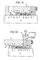
- the taper ring 5 can be attached to different positions, and Fig. 9 shows an example of attaching the taper ring 5 to a perpendicular face ( ⁇ ) standing to a radius direction from the shaft (X). Further in this example, a corner (a) of the casing (A) is cut out to form a taper face (a'). By cutting the corner, the slurry is exhausted more effectively.
- the above mentioned structure can prevent invasion of the solid materials without flusing, but addition of the flushing to the structure is preferable.
- Fig. 10 shows an embodiment providing a flushing device 6. If the flushing is undertaken, in general the sealing liquid is diluted disadvantageously, and therefore the flushing is performed intermittently herein.
- a flushing hole 60 is formed in vicinity of the the sealing face (S), into which a clean flushing liquid is supplied from a source 62 via a valve 61.
- the valve 61 is opened per determined time so as to supply the flushing liquid intermittently. Said opening may depend upon manual operation or a timer 63. Furthermore, it is considered that a rising temperature of the slurry is detected by a thermometer 64 to open the valve 61 when the temperature rises above determination. Or, the above mentioned means may be used simultaneously.
- the flushing liquid from the hole 60 pushes aside the slurry liquid around the sealing face (S), so that the slurry is avoided from staying or clogging and from overheating by cooling effect thereby at the same time. Since the flushing liquid is supplied interordinately, the slurry is not diluted.
Landscapes
- Engineering & Computer Science (AREA)
- General Engineering & Computer Science (AREA)
- Mechanical Engineering (AREA)
- Mechanical Sealing (AREA)
Applications Claiming Priority (6)
| Application Number | Priority Date | Filing Date | Title |
|---|---|---|---|
| JP10539783U JPS6014358U (ja) | 1983-07-08 | 1983-07-08 | スラリ−液用メカニカルシ−ル |
| JP105397/83 | 1983-07-08 | ||
| JP170125/83 | 1983-11-04 | ||
| JP17012583U JPS6014359U (ja) | 1983-11-04 | 1983-11-04 | スラリ−液用メカニカルシ−ル |
| JP18213083U JPS6089467U (ja) | 1983-11-28 | 1983-11-28 | スラリ−液用メカニカルシ−ル |
| JP182130/83 | 1983-11-28 |
Publications (3)
| Publication Number | Publication Date |
|---|---|
| EP0131286A2 true EP0131286A2 (de) | 1985-01-16 |
| EP0131286A3 EP0131286A3 (en) | 1985-11-13 |
| EP0131286B1 EP0131286B1 (de) | 1988-11-30 |
Family
ID=27310469
Family Applications (1)
| Application Number | Title | Priority Date | Filing Date |
|---|---|---|---|
| EP84107939A Expired EP0131286B1 (de) | 1983-07-08 | 1984-07-06 | Mechanische Dichtung zum Abdichten schlammiger Flüssigkeiten |
Country Status (3)
| Country | Link |
|---|---|
| US (1) | US4545588A (de) |
| EP (1) | EP0131286B1 (de) |
| DE (1) | DE3475426D1 (de) |
Cited By (3)
| Publication number | Priority date | Publication date | Assignee | Title |
|---|---|---|---|---|
| DE10006997C2 (de) * | 2000-02-16 | 2002-11-07 | Federal Mogul Friedberg Gmbh | Laufwerkdichtung |
| ITAN20100027A1 (it) * | 2010-03-04 | 2011-09-05 | Roberto Cipollone | Gruppo di tenuta per pompe e mescolatori di fluidi. |
| CN109340378A (zh) * | 2018-11-12 | 2019-02-15 | 中国船舶重工集团公司第七〇九研究所 | 一种自动压紧填料密封装置 |
Families Citing this family (24)
| Publication number | Priority date | Publication date | Assignee | Title |
|---|---|---|---|---|
| US4680879A (en) * | 1985-06-28 | 1987-07-21 | Pjh, Inc. | Underwater dredging apparatus and cutter head therefor |
| US5165699A (en) * | 1991-07-25 | 1992-11-24 | Arco Chemical Technology, L.P. | Liquid full pressurized vessel seal |
| US5329898A (en) * | 1993-05-05 | 1994-07-19 | Freudenerg-Nok General Partnership | Shaft seal and bore assembly |
| US6428011B1 (en) * | 1998-09-16 | 2002-08-06 | Aes Engineering Limited | Mechanical seals |
| US6412784B1 (en) * | 2000-05-26 | 2002-07-02 | The United States Of America As Represented By The Secretary Of The Navy | Split face mechanical seal system |
| US6494458B2 (en) | 2000-12-19 | 2002-12-17 | Karl E. Uth | Rotary sealing assembly |
| JP2002257070A (ja) * | 2001-02-28 | 2002-09-11 | Toyota Industries Corp | 真空ポンプにおける軸封構造 |
| GB0200695D0 (en) * | 2002-01-14 | 2002-02-27 | Aesseal Plc | An expeller device |
| GB0206263D0 (en) * | 2002-03-18 | 2002-05-01 | Aes Eng Ltd | A flow induced mechanical seal |
| US7555658B2 (en) * | 2004-09-30 | 2009-06-30 | Regents Of The University Of California | Embedded electronics building blocks for user-configurable monitor/control networks |
| US9897213B2 (en) * | 2005-03-31 | 2018-02-20 | Aes Engineering Ltd. | Flow inducing ring for a mechanical seal |
| US20080111314A1 (en) * | 2006-11-09 | 2008-05-15 | Cheng-Shiou Huang | Shaft sealing assembly with liquid stirring unit |
| US20100253005A1 (en) * | 2009-04-03 | 2010-10-07 | Liarakos Nicholas P | Seal for oil-free rotary displacement compressor |
| CN102112785B (zh) * | 2009-09-24 | 2014-12-03 | 伊格尔工业股份有限公司 | 机械密封件 |
| US8186687B2 (en) * | 2009-12-30 | 2012-05-29 | Scenic Precise Element Inc. | Cartridge seal device |
| MY175275A (en) * | 2010-11-25 | 2020-06-17 | Bin Zainal Abidin Azhar | An improved compression unit |
| DE102011118477A1 (de) * | 2011-11-14 | 2013-05-16 | Eagleburgmann Germany Gmbh & Co. Kg | Schwimmend gelagertes Fördergewinde |
| DE102011122543B4 (de) * | 2011-12-27 | 2013-09-19 | Eagleburgmann Germany Gmbh & Co. Kg | Fördereinrichtung mit flexibilisierten Strukturen für eine Gleitringdichtung |
| KR101730261B1 (ko) * | 2015-10-23 | 2017-04-25 | 두산중공업 주식회사 | 터빈의 실링 조립체 |
| CN108131323B (zh) * | 2016-01-25 | 2020-12-18 | 朱保生 | 泵停车密封装置及其工作方法 |
| CN108180140B (zh) * | 2017-12-20 | 2023-10-27 | 杭州电子科技大学 | 一种全密封型双螺杆泵 |
| US12012915B2 (en) | 2021-02-09 | 2024-06-18 | Honda Motor Co., Ltd. | Pump cover attachment system |
| JP7811519B2 (ja) * | 2022-06-16 | 2026-02-05 | 株式会社Pillar | メカニカルシール装置 |
| JP7811518B2 (ja) * | 2022-06-16 | 2026-02-05 | 株式会社Pillar | メカニカルシール装置 |
Family Cites Families (15)
| Publication number | Priority date | Publication date | Assignee | Title |
|---|---|---|---|---|
| GB191106696A (en) * | 1911-03-17 | 1911-11-30 | Thomas Forrest | Improvements in, and in the Sealing of, Glands for Compressor or Piston Rods. |
| DE353815C (de) * | 1916-08-25 | 1922-05-26 | Franz Lawaczeck Dr Ing | Abdichtung einer Maschinenwelle mittels einer viskosen Sperrfluessigkeit |
| US1997613A (en) * | 1929-09-23 | 1935-04-16 | Guysbert B Vroom | Method of and apparatus for sealing mediums from escape |
| CH141626A (de) * | 1929-10-07 | 1930-08-15 | Sulzer Ag | Stopfbüchse. |
| US2201478A (en) * | 1938-02-28 | 1940-05-21 | Eddington Metal Specialty Co | Double acting sealing means for relatively rotatable parts |
| US2297477A (en) * | 1939-07-27 | 1942-09-29 | Huhn Felix Antonius | Fluid seal |
| US2354478A (en) * | 1941-05-21 | 1944-07-25 | Dow Chemical Co | Shaft seal |
| SE310584B (de) * | 1968-02-15 | 1969-05-05 | D Huhn | |
| DE1913397B2 (de) * | 1969-03-17 | 1974-06-20 | Feodor Burgmann Jun. Asbest- Und Packungswerk, 8190 Wolfratshausen | Gleitringdichtung mit Schraubengangpumpe |
| US3765689A (en) * | 1971-09-27 | 1973-10-16 | Durametallic Corp | Mechanical seal construction |
| US4084825A (en) * | 1976-03-31 | 1978-04-18 | The United States Of America As Represented By The Administrator Of The National Aeronautics And Space Administration | Counter pumping debris excluder and separator |
| JPS583150B2 (ja) * | 1978-10-09 | 1983-01-20 | 株式会社日立製作所 | メカニカルシ−ル |
| CA1141795A (en) * | 1978-12-01 | 1983-02-22 | Peter Hold | Seals for rotary processor |
| US4243230A (en) * | 1979-10-01 | 1981-01-06 | Crane Packing Co. | Low energy tandem seal |
| DE3021847A1 (de) * | 1980-06-11 | 1981-12-24 | Industrie-Seal-Technik GmbH Dichtungs-Maschinen + Apparatebau, 6000 Frankfurt | Ptfe-belag-gleitringdichtung |
-
1984
- 1984-07-06 EP EP84107939A patent/EP0131286B1/de not_active Expired
- 1984-07-06 US US06/628,241 patent/US4545588A/en not_active Expired - Fee Related
- 1984-07-06 DE DE8484107939T patent/DE3475426D1/de not_active Expired
Cited By (5)
| Publication number | Priority date | Publication date | Assignee | Title |
|---|---|---|---|---|
| DE10006997C2 (de) * | 2000-02-16 | 2002-11-07 | Federal Mogul Friedberg Gmbh | Laufwerkdichtung |
| EP1126201A3 (de) * | 2000-02-16 | 2005-01-26 | Federal-Mogul Friedberg GmbH | Laufwerkdichtung |
| ITAN20100027A1 (it) * | 2010-03-04 | 2011-09-05 | Roberto Cipollone | Gruppo di tenuta per pompe e mescolatori di fluidi. |
| CN109340378A (zh) * | 2018-11-12 | 2019-02-15 | 中国船舶重工集团公司第七〇九研究所 | 一种自动压紧填料密封装置 |
| CN109340378B (zh) * | 2018-11-12 | 2023-12-01 | 中国船舶重工集团公司第七一九研究所 | 一种自动压紧填料密封装置 |
Also Published As
| Publication number | Publication date |
|---|---|
| EP0131286B1 (de) | 1988-11-30 |
| US4545588A (en) | 1985-10-08 |
| EP0131286A3 (en) | 1985-11-13 |
| DE3475426D1 (en) | 1989-01-05 |
Similar Documents
| Publication | Publication Date | Title |
|---|---|---|
| EP0131286B1 (de) | Mechanische Dichtung zum Abdichten schlammiger Flüssigkeiten | |
| US4572517A (en) | Labyrinth ring seals with housing mounting means | |
| US6688601B2 (en) | Mechanical seal | |
| JP3616808B2 (ja) | ポンプ | |
| CA2017064A1 (en) | Helical cut seal | |
| EP1666762A1 (de) | Rotierender dämpfer | |
| DE2935565C2 (de) | ||
| US4496135A (en) | Alignment maintaining apparatus for trunnion mounted valves | |
| EP1471341B1 (de) | Kleinbauende Sensorbefestigung an einem Behältnis mit einer konzentrischen Druckschraube | |
| US3803685A (en) | Ball joint and method of fabrication | |
| US12038091B2 (en) | Rotary valve with reduced flushing time | |
| US3918474A (en) | Capacitor fill tube and seal | |
| US2552110A (en) | Frangible port closure | |
| US5326079A (en) | Self-sealing valve body and orifice member assembly | |
| JP6283151B1 (ja) | 流体ダンパ装置およびダンパ付き機器 | |
| US2986960A (en) | Gun drill and the method of producing the same | |
| US3991701A (en) | Bearing wear detecting device for canned motor driven pumps | |
| CA1171669A (en) | Water-resistant device between an outside control member and watch case | |
| JPS58171219A (ja) | 放電加工用電極 | |
| JP3149589B2 (ja) | ストレーナ | |
| JPS6128483Y2 (de) | ||
| JPS6224664B2 (de) | ||
| JPS6253746B2 (de) | ||
| US3528641A (en) | Tubular valve | |
| JP2874050B2 (ja) | 粉末容器 |
Legal Events
| Date | Code | Title | Description |
|---|---|---|---|
| PUAI | Public reference made under article 153(3) epc to a published international application that has entered the european phase |
Free format text: ORIGINAL CODE: 0009012 |
|
| AK | Designated contracting states |
Designated state(s): AT BE CH DE FR GB IT LI LU NL SE |
|
| RBV | Designated contracting states (corrected) |
Designated state(s): DE FR GB SE |
|
| PUAL | Search report despatched |
Free format text: ORIGINAL CODE: 0009013 |
|
| AK | Designated contracting states |
Designated state(s): DE FR GB SE |
|
| 17P | Request for examination filed |
Effective date: 19851210 |
|
| 17Q | First examination report despatched |
Effective date: 19870216 |
|
| GRAA | (expected) grant |
Free format text: ORIGINAL CODE: 0009210 |
|
| AK | Designated contracting states |
Kind code of ref document: B1 Designated state(s): DE FR GB SE |
|
| REF | Corresponds to: |
Ref document number: 3475426 Country of ref document: DE Date of ref document: 19890105 |
|
| ET | Fr: translation filed | ||
| PLBE | No opposition filed within time limit |
Free format text: ORIGINAL CODE: 0009261 |
|
| STAA | Information on the status of an ep patent application or granted ep patent |
Free format text: STATUS: NO OPPOSITION FILED WITHIN TIME LIMIT |
|
| 26N | No opposition filed | ||
| EAL | Se: european patent in force in sweden |
Ref document number: 84107939.5 |
|
| PGFP | Annual fee paid to national office [announced via postgrant information from national office to epo] |
Ref country code: SE Payment date: 19960703 Year of fee payment: 13 Ref country code: GB Payment date: 19960703 Year of fee payment: 13 |
|
| PGFP | Annual fee paid to national office [announced via postgrant information from national office to epo] |
Ref country code: FR Payment date: 19960712 Year of fee payment: 13 |
|
| PGFP | Annual fee paid to national office [announced via postgrant information from national office to epo] |
Ref country code: DE Payment date: 19960827 Year of fee payment: 13 |
|
| PG25 | Lapsed in a contracting state [announced via postgrant information from national office to epo] |
Ref country code: GB Free format text: LAPSE BECAUSE OF NON-PAYMENT OF DUE FEES Effective date: 19970706 |
|
| PG25 | Lapsed in a contracting state [announced via postgrant information from national office to epo] |
Ref country code: SE Effective date: 19970707 |
|
| GBPC | Gb: european patent ceased through non-payment of renewal fee |
Effective date: 19970706 |
|
| PG25 | Lapsed in a contracting state [announced via postgrant information from national office to epo] |
Ref country code: FR Free format text: LAPSE BECAUSE OF NON-PAYMENT OF DUE FEES Effective date: 19980331 |
|
| PG25 | Lapsed in a contracting state [announced via postgrant information from national office to epo] |
Ref country code: DE Free format text: LAPSE BECAUSE OF NON-PAYMENT OF DUE FEES Effective date: 19980401 |
|
| EUG | Se: european patent has lapsed |
Ref document number: 84107939.5 |
|
| REG | Reference to a national code |
Ref country code: FR Ref legal event code: ST |