EP0131367B1 - Verfahren und Einrichtung zum Bearbeiten von keramischen Werkstoffen - Google Patents
Verfahren und Einrichtung zum Bearbeiten von keramischen Werkstoffen Download PDFInfo
- Publication number
- EP0131367B1 EP0131367B1 EP84303619A EP84303619A EP0131367B1 EP 0131367 B1 EP0131367 B1 EP 0131367B1 EP 84303619 A EP84303619 A EP 84303619A EP 84303619 A EP84303619 A EP 84303619A EP 0131367 B1 EP0131367 B1 EP 0131367B1
- Authority
- EP
- European Patent Office
- Prior art keywords
- workpiece
- region
- electrodes
- liquid electrolyte
- energy
- Prior art date
- Legal status (The legal status is an assumption and is not a legal conclusion. Google has not performed a legal analysis and makes no representation as to the accuracy of the status listed.)
- Expired
Links
Images

Classifications
-
- B—PERFORMING OPERATIONS; TRANSPORTING
- B23—MACHINE TOOLS; METAL-WORKING NOT OTHERWISE PROVIDED FOR
- B23K—SOLDERING OR UNSOLDERING; WELDING; CLADDING OR PLATING BY SOLDERING OR WELDING; CUTTING BY APPLYING HEAT LOCALLY, e.g. FLAME CUTTING; WORKING BY LASER BEAM
- B23K26/00—Working by laser beam, e.g. welding, cutting or boring
- B23K26/12—Working by laser beam, e.g. welding, cutting or boring in a special environment or atmosphere, e.g. in an enclosure
- B23K26/127—Working by laser beam, e.g. welding, cutting or boring in a special environment or atmosphere, e.g. in an enclosure in an enclosure
-
- B—PERFORMING OPERATIONS; TRANSPORTING
- B23—MACHINE TOOLS; METAL-WORKING NOT OTHERWISE PROVIDED FOR
- B23K—SOLDERING OR UNSOLDERING; WELDING; CLADDING OR PLATING BY SOLDERING OR WELDING; CUTTING BY APPLYING HEAT LOCALLY, e.g. FLAME CUTTING; WORKING BY LASER BEAM
- B23K26/00—Working by laser beam, e.g. welding, cutting or boring
- B23K26/12—Working by laser beam, e.g. welding, cutting or boring in a special environment or atmosphere, e.g. in an enclosure
-
- B—PERFORMING OPERATIONS; TRANSPORTING
- B23—MACHINE TOOLS; METAL-WORKING NOT OTHERWISE PROVIDED FOR
- B23K—SOLDERING OR UNSOLDERING; WELDING; CLADDING OR PLATING BY SOLDERING OR WELDING; CUTTING BY APPLYING HEAT LOCALLY, e.g. FLAME CUTTING; WORKING BY LASER BEAM
- B23K26/00—Working by laser beam, e.g. welding, cutting or boring
- B23K26/16—Removal of by-products, e.g. particles or vapours produced during treatment of a workpiece
-
- B—PERFORMING OPERATIONS; TRANSPORTING
- B23—MACHINE TOOLS; METAL-WORKING NOT OTHERWISE PROVIDED FOR
- B23K—SOLDERING OR UNSOLDERING; WELDING; CLADDING OR PLATING BY SOLDERING OR WELDING; CUTTING BY APPLYING HEAT LOCALLY, e.g. FLAME CUTTING; WORKING BY LASER BEAM
- B23K26/00—Working by laser beam, e.g. welding, cutting or boring
- B23K26/36—Removing material
- B23K26/40—Removing material taking account of the properties of the material involved
-
- B—PERFORMING OPERATIONS; TRANSPORTING
- B23—MACHINE TOOLS; METAL-WORKING NOT OTHERWISE PROVIDED FOR
- B23P—METAL-WORKING NOT OTHERWISE PROVIDED FOR; COMBINED OPERATIONS; UNIVERSAL MACHINE TOOLS
- B23P25/00—Auxiliary treatment of workpieces, before or during machining operations, to facilitate the action of the tool or the attainment of a desired final condition of the work, e.g. relief of internal stress
- B23P25/003—Auxiliary treatment of workpieces, before or during machining operations, to facilitate the action of the tool or the attainment of a desired final condition of the work, e.g. relief of internal stress immediately preceding a cutting tool
- B23P25/006—Heating the workpiece by laser during machining
-
- B—PERFORMING OPERATIONS; TRANSPORTING
- B24—GRINDING; POLISHING
- B24B—MACHINES, DEVICES, OR PROCESSES FOR GRINDING OR POLISHING; DRESSING OR CONDITIONING OF ABRADING SURFACES; FEEDING OF GRINDING, POLISHING, OR LAPPING AGENTS
- B24B1/00—Processes of grinding or polishing; Use of auxiliary equipment in connection with such processes
-
- C—CHEMISTRY; METALLURGY
- C25—ELECTROLYTIC OR ELECTROPHORETIC PROCESSES; APPARATUS THEREFOR
- C25F—PROCESSES FOR THE ELECTROLYTIC REMOVAL OF MATERIALS FROM OBJECTS; APPARATUS THEREFOR
- C25F3/00—Electrolytic etching or polishing
- C25F3/02—Etching
- C25F3/14—Etching locally
-
- C—CHEMISTRY; METALLURGY
- C25—ELECTROLYTIC OR ELECTROPHORETIC PROCESSES; APPARATUS THEREFOR
- C25F—PROCESSES FOR THE ELECTROLYTIC REMOVAL OF MATERIALS FROM OBJECTS; APPARATUS THEREFOR
- C25F7/00—Constructional parts, or assemblies thereof, of cells for electrolytic removal of material from objects; Servicing or operating
-
- B—PERFORMING OPERATIONS; TRANSPORTING
- B23—MACHINE TOOLS; METAL-WORKING NOT OTHERWISE PROVIDED FOR
- B23K—SOLDERING OR UNSOLDERING; WELDING; CLADDING OR PLATING BY SOLDERING OR WELDING; CUTTING BY APPLYING HEAT LOCALLY, e.g. FLAME CUTTING; WORKING BY LASER BEAM
- B23K2103/00—Materials to be soldered, welded or cut
- B23K2103/50—Inorganic materials other than metals or composite materials
- B23K2103/52—Ceramics
Definitions
- the present invention relates to a method of and apparatus for machining a workpiece of a ceramic material, i.e. a ceramic such as a metal oxide, nitride, carbide, boride, silicide, fluoride, sulfide, phosphide, arsenide or selenide, a composite of one or more ceramics, or a composite of one or more ceramics with one or more metals, known as cermet, ceramet or ceramal.
- a ceramic material i.e. a ceramic such as a metal oxide, nitride, carbide, boride, silicide, fluoride, sulfide, phosphide, arsenide or selenide, a composite of one or more ceramics, or a composite of one or more ceramics with one or more metals, known as cermet, ceramet or ceramal.
- ceramic materials Because of their unique, excellent properties not generally offered by metals (e.g. hardness, high melting point and chemical stability), ceramic materials have been known to be highly useful materials. Unfortunately, these materials are not only hard but brittle and electrically nonconductive so that they are not readily machinable by an existing machining technique, e.g. abrasive grinding or cutting, electrical discharge machining or electrochemical machining. Accordingly there have been severe limitations in their uses and expanding their industrial applicabilities.
- a method of machining a workpiece of ceramic material comprising the steps of delivering to the workpiece a liquid electrolyte having at least one component to which said material is normally inert but with which it becomes chemically reactive at an elevated temperature applying to a limited zone of interface between said liquid electrolyte and said workpiece localised energy of a magnitude sufficient to heat said electrolyte and said ceramic material at said limited zone to said elevated temperature, characterised by the steps of dislodging by abrasion or by electrical discharge erosion any material at least partially chemically degenerated by said heated liquid electrolyte at said limited zone, and progressively displacing said limited zone from one region to another on said workpiece along a predetermined continuous path defining the region of the workpiece to be machined.
- an apparatus for machining a workpiece of a ceramic material comprising:
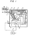
- a workpiece 1 composed of a ceramic material is securely mounted on a worktable 2.
- the worktable is an upper drive table which is movably mounted on a lower drive table 3 which is in turn movably mounted on a machining base 4.
- the upper and lower drive tables 2 and 3 are in a conventional cross-feed arrangement on the base 4 and are moved by motors 5 and 6, respectively, which are driven by command signals furnished from a control unit 7, e.g an NC (numerical controller), to displace the workpiece 1 along a programmed path in a horizontal or X-Y plane.
- a control unit 7 e.g an NC (numerical controller
- the base 4 has a column 8 standing upright thereon which carries a pair of horizontally extending heads 9 and 10.
- the upper head 9 mounted on the lower head 10 carries at its end portion a liquid delivery unit 11 and a beam gun 12 while the lower head 10 carries at its end a rotary abrasive wheel 13 which is rotated by a motor (not shown).
- the head 10 is movable vertically or along a Z-axis and so moved by a motor 14 provided thereon to jointly move the liquid delivery unit 11, the beam gun 12 and the abrasive wheel 13 up and down.
- the liquid delivery unit 11 comprises a nozzle 11a towards its lower end, communicates via a supply conduit 15 with a tank 16 containing a liquid electrolyte and accommodated in the base 4.
- the liquid electrolyte in the tank 16 is controlledly drawn by a pump (not shown) through a liquid supply control unit 17 and the delivery unit 11 on to the workpiece 1.
- the beam gun 12 is connected to a source 18 of an energy beam such as a laser beam or microwave beam.
- the energy beam from the source 18 is guided by a reflector 19 and a lens 20 to pass out of the gun 12 on to the workpiece 1.
- the motor 14 is furnished from the NC unit 7 with command signals to move the heads 9 and 10 jointly and the rotating wheel 13 into abrasive contact with the workpiece 1.
- the beam gun 12 is pivotally mounted on the head 9 to be swivelable to enable adjustment of the position of impingement of the energy beam on the workpiece 1 with respect to the position of abrasive contact of the wheel 13 with the workpiece 1.
- the liquid delivery unit 1 may be arranged to be movable jointly with the beam gun 12.
- the nozzle portion 11a of the liquid delivery nozzle unit 11 is flexible and bendable but self-sustaining so that -the nozzle opening may be disposed at a desired position with respect to the beam gun 12 and the abrasive wheel 13 by manipulating the physical flexibility of that portion.
- the liquid electrolyte is preferably an aqueous solution of a strong acid (e.g. hydrogen chloride, hydrogen sulfate or hydrogen nitrate) providing hydrogen ions or a strong base (e.g. sodium hydroxide or potassium hydroxide) providing hydroxide ions.
- a strong acid e.g. hydrogen chloride, hydrogen sulfate or hydrogen nitrate
- a strong base e.g. sodium hydroxide or potassium hydroxide
- a ceramic material is highly inert to such chemicals under normal conditions or at a room temperature but becomes highly reactive with hydrogen and/or hydroxide ions at an elevated temperature. Water (e.g. distilled) is also suitable since it upon electrolysis provides hydrogen and hydroxide ions.
- the liquid electrolyte from the reservoir 16 is controlledly delivered through the nozzle unit 11 on to the surface of the workpiece 1.
- the control unit 16 is adjusted to deliver the liquid electrolyte at a volume flow rate, say, between 1 and 100 cc/s and at a velocity, say, between 10 and 100 m/s.
- the liquid electrolyte may flow on the workiece 1, traversing the path of the energy beam directed from the gun 12 on to the workpiece 1.
- the energy beam is focussed by the lens 20 to impinge on a narrow spot or limited zone of a size generally between 1 and 100 pm, preferably not greater than 10 pm, at an interface between the liquid electrolyte and the workpiece 1 so that the latter two at that spot is instantaneously heated up to an elevated temperature sufficient to cause a portion of the ceramic material with activated hydrogen and/or hydroxyde ions or radicals.
- the localized beam energy produces at least a partially chemically degenerated zone of ceramic material on workpiece 1 which is then dislodged or removed by abrasion.
- the motors 5 and 6 are driven under control commands from the NC unit 7 to displace the workpiece 1 accordingly.
- the abrasive wheel 13, which is rotated in the direction of the arrow, is one means of applying a mechanical action to an area on the workpiece immediately behind an area of impingement of the energy beam, thereby facilitating removal of the beam degenerated area from the workpiece 1.
- the beam gun 12 is swivelably oscillated by means not shown to oscillate the energy beam transversely, i.e.
- the beam gun 12 may be oscillated at a frequency of, say, 100 KHz to 200 MHz.
- the vertical position of the abrasive wheel 13 and the rate of displacement of the workpiece 1 are set in the NC unit 7 in conjunction with the depth of material removal or machining desired in the workpiece 1.
- the energy beam source 18 may have a variable setting, which can again be controlled by the NC unit 7, to change the energy and/or the focal point of the beam as machining proceeds in the workpiece 1.
- the supply control unit 16 for the liquid electrolyte also has a variable setting which may again be controlled by the NC unit to change the pressure, flow rate and/or velocity of the liquid electrolyte delivered on to the workpiece 1.
- the energy beam may be a beam of laser, microwaves or plasma and generally should have an energy density in excess of 10 2 watts/cm2 but not in excess of 10 6 watts/cm2. It has been found that best results are most often obtained when the beam energy ranges between 10 3 and 10 4 watts/cm 2 or up to 5 x 10 5 watts/cm2.
- two or more different forms of energy beams are jointly employed.
- an energy beam is preferably employed jointly with one or more different forms of localized energization such as ultrasonic mechanical vibrations or electrical discharge energy as will be described.
- a cover member 21 is provided to accommodate the machining space and to prevent the liquid electrolyte and machining products from splashing or emitting into the environment. Mists and gases evolved in the machining zone are confined within a chamber defined by the cover member 19 and are drawn by means of a suction pump 22 outside of the chamber and rendered harmless by a conventional mist/gas treatment unit 23.
- FIG. 2 shows a modification of a portion of the embodiment of FIG. 1 in which the abrasive wheel (13) is replaced by a fluid honing nozzle 24 and the beam gun 12 as well as the fluid honing nozzle 24 can be oriented towards successive spots on a programmed machining path in spite of changes in the course thereof.
- a liquid delivery unit 11 having a nozzle 11 a extending vertically is securely supported by a holder 25 which is in turn secured to the lower head 10.
- the liquid delivery unit 11 has an inlet fed with the liquid electrolyte from the supply control unit 17 (FIG 1) to deliver it on to the workpiece 1 through the nozzle 11a.
- the fluid honing nozzle 24 obliquely oriented towards a region on the programmed machining path is provided with a fluid inlet chamber 25 which communicates with a source 26 of an abrasive honing fluid.
- the chamber 25 is secured to a rotary carriage 27 which is rotatable about the holder 25 coaxially therewith.
- the rotary carriage 27 is rotated by a motor 28 which is drivingly coupled therewith via a gear transmission 29.
- the motor 28 is carried by the upper head 9 and is adapted to be controlledly driven in response to command signals from the NC unit 7.
- the beam gun 12 is obliquely oriented towards a region on the programmed machining path depends from an attachment 30 which is in turn secured to a rotary carriage 31.
- the latter is rotatable about the rotary carriage 27 coaxially therewith and rotated by a motor 32 which is drivingly coupled therewith via a gear transmission 33.
- the motor 32 is carried by the head 9 and is adapted to be controlledly driven in response to command signals from to NC unit 7.
- the beam gun 12 may here again be for a laser beam and is shown as being connected via a flexible optical transmission 34 with a source of laser 18 (FIG. 1).
- the motor 32 for positioning the beam gun 12 and the motor 28 for positioning the fluid honing nozzle 24 may be controlled so that when the liquid delivery nozzle 11a is vertically oriented towards a first region on the programmed machining path, the beam gun 12 remains obliquely oriented towards a second region adjacent to the first region on the programmed machining path and the fluid honing nozzle 24 remains obliquely oriented towards a third region immediately behind the second region along the programmed machining path in spite of changes in the course of a programmed machining path.
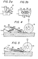
- FIGS. 3a, 3b, 4 and 5 show modifications of the embodiments of FIGS. 1 and 2 in which the beam energy is combined with electrical discharge energy to effect both heating and a mechanical dislodgement action to a localized area at the interface between the liquid electrolyte supplied from the delivery nozzle 11a and the ceramic material 1.
- a pair of heat- resistant electrodes 35 are shown as attached to the beam gun 12 via respective holders 36 so as to be spacedly juxtaposed with each other across a space immediately ahead of the gun opening 12a and to be disposed in contact with the liquid electrolyte L delivered from the nozzle 11a on to the workpiece 1.
- a power supply (not shown) is electrically connected to the electrodes 35 to supply an electrical power in the form of a continuous DC or preferably a succession of pulses between them across the liquid electrolyte L, the electric power being of a voltage and current sufficient to effect electrical discharge erosion of the ceramic material through a portion of the electrolyte.
- the chemically degenerated ceramic stock is thus dislodged from the workpiece I.
- the discharge electrodes 35 are shown as being attached to the electrolyte delivery nozzle 11a.
- the nozzle 11a is here formed with a narrow rectangular nozzle opening 11b (e.g. 1 mm thick and 10 mm wide) adapted to deliver a thin, film-like flow of the liquid electrolyte (e.g. an aqueous solution containing 5 to 40 % by weight hydrogen chloride) at a velocity of 10 to 100 metres/second and a flow rate of 1 to 100 cc.
- the liquid electrolyte e.g. an aqueous solution containing 5 to 40 % by weight hydrogen chloride
- One of the electrodes 35a is mounted directly on the nozzle 11a adjacent to the opening 11b and the other 35b is 6 supported by the nozzle by means of the holder 3 so as to lie ahead of the nozzle opening 11b.
- the electrode 35b is poled positive and the electrode 35a negative since electrical discharges tends to concentrate at the positive electrode, thus closer to the workpiece 1.
- the abrasive wheel 13 is disposed ahead of the electrode 35b to abrade the chemically degenerated layer 1a, thereby mechanically facilitating removal thereof from the workpiece 1.
- the abrasive wheel 13 is preferably of an electrically conductive abrasive body as prepared by sintering a mixture of titanium carbide and/or titanium nitride with diamond, boron carbide, cubic boron nitride and/or silicon carbide. Then, preferably the wheel 13 is electrically poled negative with respect to both electrodes 35a and 35b to prevent it from being worn by electrolytic erosion.
- the electrode 35a in FIG. 4 is omitted, and the electrically conductive abrasive wheel 13 is poled negative while the electrode 35b is poled positive to pass discharge energization current directly through a region therebetween.
- a localized area 1a of the ceramic material when heated at an elevated temperature, becomes electrically conductive and hence comes to act as an intermediate electrode to carry the discharge current which is deflected as shown at D. Increased localization of the discharge energy is thus obtained.
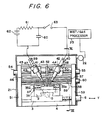
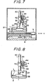
- FIGS. 6 and 7 in which the same reference numerals as in the previous FIGURES are used to designate the same or similar functional elements, a pair of elongate discharge electrodes 35a, 35b, each in the form of a rod or kneedle, are shown as juxtaposed with the workpiece 1 of a ceramic material securely accommodated in a worktank 37 defined by the worktable 2 and side walls 38.
- One or each of the electrodes may also be in the form of a conductive disk or wheel as shown at 35' in FIG. 8.
- the liquid electrolyte L supplied on to the workpiece 1 from a delivery nozzle 11 is shown as collected in the worktank 37.
- Each of the electrodes 35a, 35b is securely held by a holder 39, 40 extending coaxially therewith, which is in turn slidably movable through a bracket 41, 42.
- the brackets 41 and 42 are pivotally mounted on carriages 43 and 44, respectively, which are slidably movable horizontally between an upper and a lower beam 45, 46.
- the brackets 41 and 42 are secured to the carriages 43 and 44 so that the electrodes 35a and 35b are inclined downwards and approach each other along their axes towards the workpiece 1.
- Each of the holders 39, 40 and hence the electrodes 35a, 35b is movable axially by a motor 47, 48 securely mounted on the brackets 41, 42 and is secured in position where each electrode free end has a given small spacing with the workpiece 1.
- the carriages 43 and 44 are movable on horizontal lead screws 49 and 50 which are journaled between one side post 51 and a central bracket 52 and between the latter and the other side post 53, respectively, both the posts standing upright on the base 4.
- the parallel beams 45 and 46 are also supported by and extend between the posts 51 and 53.
- the lead screws 49 and 50 are driven by motors 54 and 55 secured to the posts 51 and 53, respectively, for positioning the carriages 43 and 44.
- a partition plate 56 Disposed vertically between the forwardly inclined electrodes 35a and 35b is a partition plate 56 composed of an insulating material and supported by another set of parallel beams 57 and 58, each of which extends horizontally between the side posts 51 and 53.
- the partition plate 56 is horizontally movable on a lead screw 59 journaled on the side posts 51 and 53.
- the lead screw 59 is driven by a motor 60 mounted on the post 53 for positioning the partition plate 56.
- the partition plate 56 is preferably constituted as a fluid delivery nozzle 11 by being formed with a nozzle opening 11b and an internal bore to communicate with the source 16 of the liquid electrolyte and the supply control unit 17 (FIG. 1).
- a nozzle is preferably arranged to also form an abrasive honing nozzle.
- means may be provided to introduce abrasive particles into the liquid electrolyte prior to entry into the partition 56.
- a power supply for energizing the electrodes 35a, 35b may comprise a capacitor 60 periodically chargeable via a resistor 61 by a DC source 62 and dischargeable across the electrodes 35a and 35b via a switch 63.
- the switch 63 is of electronic type and alternately turned on and off in response to periodic switching signals furnished from an oscillator (not shown). Each time the switch 63 is turned on, an impulsive electrical discharge is passed across a small spacing between the electrodes 35a and 35b through a film of the liquid electrolyte adjacent the workpiece 1.
- the insulating partition 36 is provided to confine the electrical discharge closer to the workpiece 1.
Landscapes
- Engineering & Computer Science (AREA)
- Mechanical Engineering (AREA)
- Physics & Mathematics (AREA)
- Optics & Photonics (AREA)
- Plasma & Fusion (AREA)
- Chemical & Material Sciences (AREA)
- Chemical Kinetics & Catalysis (AREA)
- Electrochemistry (AREA)
- Materials Engineering (AREA)
- Metallurgy (AREA)
- Organic Chemistry (AREA)
- Electrical Discharge Machining, Electrochemical Machining, And Combined Machining (AREA)
Claims (17)
gekennzeichnet durch Mittel zum Entfernen jedes wenigstens teilweise chemisch durch den erhitzten flüssigen Elektrolyt an der beschränkten Zone entarteten Materials durch Abrieb oder durch Funkenerosion und
Applications Claiming Priority (4)
| Application Number | Priority Date | Filing Date | Title |
|---|---|---|---|
| JP58096727A JPS59223282A (ja) | 1983-05-30 | 1983-05-30 | セラミツクスの加工方法 |
| JP96727/83 | 1983-05-30 | ||
| JP9758683A JPS59224216A (ja) | 1983-05-31 | 1983-05-31 | 不良導体の放電加工方法 |
| JP97586/83 | 1983-05-31 |
Publications (2)
| Publication Number | Publication Date |
|---|---|
| EP0131367A1 EP0131367A1 (de) | 1985-01-16 |
| EP0131367B1 true EP0131367B1 (de) | 1989-04-05 |
Family
ID=26437905
Family Applications (1)
| Application Number | Title | Priority Date | Filing Date |
|---|---|---|---|
| EP84303619A Expired EP0131367B1 (de) | 1983-05-30 | 1984-05-30 | Verfahren und Einrichtung zum Bearbeiten von keramischen Werkstoffen |
Country Status (3)
| Country | Link |
|---|---|
| US (1) | US4559115A (de) |
| EP (1) | EP0131367B1 (de) |
| DE (2) | DE131367T1 (de) |
Cited By (2)
| Publication number | Priority date | Publication date | Assignee | Title |
|---|---|---|---|---|
| DE102005043209A1 (de) * | 2005-09-09 | 2007-03-15 | Fraunhofer-Gesellschaft zur Förderung der angewandten Forschung e.V. | Verfahren und Vorrichtung zur spanenden Bearbeitung von Werkstücken aus Glas oder Glaskeramik |
| DE202008011646U1 (de) * | 2008-09-02 | 2010-01-28 | BECKMANN-INSTITUT für Technologieentwicklung e.V. | Einrichtung zum Plasmapolieren unter Verwendung eines flüssigen Elektrolyten |
Families Citing this family (16)
| Publication number | Priority date | Publication date | Assignee | Title |
|---|---|---|---|---|
| US4497692A (en) * | 1983-06-13 | 1985-02-05 | International Business Machines Corporation | Laser-enhanced jet-plating and jet-etching: high-speed maskless patterning method |
| DE3706124A1 (de) * | 1987-02-25 | 1988-09-08 | Agie Ag Ind Elektronik | Verfahren zum elektroerosiven bearbeiten von elektrisch schwach oder nicht leitenden werkstuecken sowie elektroerosionsmaschine zur durchfuehrung des verfahrens |
| EP0300224B2 (de) * | 1987-06-26 | 1998-09-30 | Yuzo Mori | Präzises spannungsfreies Nachbehandlungsverfahren durch Radikalreaktionen |
| US4980534A (en) * | 1988-11-18 | 1990-12-25 | Toyoda Koki Kabushiki Kaisha | Method and device for treating machined surface of workpiece |
| JPH0714823B2 (ja) * | 1991-12-02 | 1995-02-22 | 東洋ガラス株式会社 | ガラスの切断方法 |
| JP2896726B2 (ja) * | 1992-03-30 | 1999-05-31 | セイコーインスツルメンツ株式会社 | 微細加工装置 |
| JPH0822483B2 (ja) * | 1993-08-05 | 1996-03-06 | 工業技術院長 | レーザ放電誘導式放電加工装置 |
| DE19518270C1 (de) | 1995-05-18 | 1996-08-22 | Fraunhofer Ges Forschung | Rutschfester Fußbodenbelag und Verfahren zu seiner Herstellung |
| US5773369A (en) * | 1996-04-30 | 1998-06-30 | The Regents Of The University Of California | Photoelectrochemical wet etching of group III nitrides |
| JP2001239795A (ja) * | 2000-02-28 | 2001-09-04 | Ando Electric Co Ltd | 打刻方法及びその装置 |
| US7329361B2 (en) * | 2003-10-29 | 2008-02-12 | International Business Machines Corporation | Method and apparatus for fabricating or altering microstructures using local chemical alterations |
| DE502004003494D1 (de) * | 2004-12-07 | 2007-05-24 | Delphi Tech Inc | Verfahren zur Herstellung einer in einem Hohlraum eines Werkstückes mündenden Bohrung mittels Laserstrahlung mit chemischer Behandlung des Hohlraumes |
| CN100418685C (zh) * | 2005-05-27 | 2008-09-17 | 江苏技术师范学院 | 非导电硬质材料的电火花成型加工方法 |
| US8764515B2 (en) * | 2012-05-14 | 2014-07-01 | United Technologies Corporation | Component machining method and assembly |
| US9039887B2 (en) * | 2012-05-14 | 2015-05-26 | United Technologies Corporation | Component finishing method and assembly |
| JP7438490B2 (ja) * | 2020-03-31 | 2024-02-27 | 国立大学法人岩手大学 | 機械加工システム |
Citations (1)
| Publication number | Priority date | Publication date | Assignee | Title |
|---|---|---|---|---|
| EP0129603A1 (de) * | 1982-12-17 | 1985-01-02 | Inoue-Japax Research Incorporated | Zerspanungsvorrichtung mit laser |
Family Cites Families (10)
| Publication number | Priority date | Publication date | Assignee | Title |
|---|---|---|---|---|
| AT165319B (de) * | ||||
| GB847927A (en) * | 1955-10-11 | 1960-09-14 | Philco Corp | A method and apparatus for the electrolytic treatment of semiconductive bodies |
| US3364087A (en) * | 1964-04-27 | 1968-01-16 | Varian Associates | Method of using laser to coat or etch substrate |
| US3475312A (en) * | 1965-06-07 | 1969-10-28 | Inoue K | Electrolytic lathe and grinding apparatus employing a homogeneous carbon electrode-tool |
| US3706645A (en) * | 1971-09-30 | 1972-12-19 | Us Army | Process including photolytic enhancement for anodic dissolution of a gallium arsenide wafer |
| LU71852A1 (de) * | 1975-02-14 | 1977-01-05 | ||
| US4283259A (en) * | 1979-05-08 | 1981-08-11 | International Business Machines Corporation | Method for maskless chemical and electrochemical machining |
| US4379022A (en) * | 1979-05-08 | 1983-04-05 | International Business Machines Corporation | Method for maskless chemical machining |
| DE3029792A1 (de) * | 1980-08-06 | 1982-03-11 | Siemens AG, 1000 Berlin und 8000 München | Verfahren zum zerteilen eines halbleiterkristalls in scheiben |
| GB2106541B (en) * | 1981-06-24 | 1984-11-21 | Ohyo Jiki Lab Co Ltd | Electrolytic and electric discharge machining of electrically non-conductive workpieces |
-
1984
- 1984-05-30 EP EP84303619A patent/EP0131367B1/de not_active Expired
- 1984-05-30 DE DE198484303619T patent/DE131367T1/de active Pending
- 1984-05-30 DE DE8484303619T patent/DE3477590D1/de not_active Expired
- 1984-05-30 US US06/615,416 patent/US4559115A/en not_active Expired - Lifetime
Patent Citations (1)
| Publication number | Priority date | Publication date | Assignee | Title |
|---|---|---|---|---|
| EP0129603A1 (de) * | 1982-12-17 | 1985-01-02 | Inoue-Japax Research Incorporated | Zerspanungsvorrichtung mit laser |
Cited By (2)
| Publication number | Priority date | Publication date | Assignee | Title |
|---|---|---|---|---|
| DE102005043209A1 (de) * | 2005-09-09 | 2007-03-15 | Fraunhofer-Gesellschaft zur Förderung der angewandten Forschung e.V. | Verfahren und Vorrichtung zur spanenden Bearbeitung von Werkstücken aus Glas oder Glaskeramik |
| DE202008011646U1 (de) * | 2008-09-02 | 2010-01-28 | BECKMANN-INSTITUT für Technologieentwicklung e.V. | Einrichtung zum Plasmapolieren unter Verwendung eines flüssigen Elektrolyten |
Also Published As
| Publication number | Publication date |
|---|---|
| DE3477590D1 (en) | 1989-05-11 |
| EP0131367A1 (de) | 1985-01-16 |
| US4559115A (en) | 1985-12-17 |
| DE131367T1 (de) | 1985-11-21 |
Similar Documents
| Publication | Publication Date | Title |
|---|---|---|
| US4559115A (en) | Method of and apparatus for machining ceramic materials | |
| US4328257A (en) | System and method for plasma coating | |
| Snoeys et al. | Current trends in non-conventional material removal processes | |
| Gautam et al. | Experimental investigations into ECSD process using various tool kinematics | |
| US7394040B2 (en) | Electromachining process and apparatus | |
| EP1244533A1 (de) | Verfahren und vorrichtung zum elektrochemischen bearbeiten | |
| US20090314748A1 (en) | Ultrasonic assisted electrodischarge machining | |
| CN1016764B (zh) | 加工稍微导电或不导电工件的电腐蚀机 | |
| US5045161A (en) | Method and apparatus for electrolytically assisting the mechanical shaping of a workpiece | |
| Saxena et al. | Electrochemical Based Hybrid Machining A2-Luo, Xichun | |
| Ranjan et al. | A comprehensive review on the machining process: unconventional as an alternative to conventional machining | |
| Mahamood et al. | Advanced noncontact cutting and joining technologies | |
| US6020568A (en) | Electro mechanical process and apparatus for metal deposition | |
| EP0468110B1 (de) | Elektrische Lichtbogenbehandlung von Teilchen | |
| Alting et al. | Nontraditional manufacturing processes | |
| US4458130A (en) | Immersion-type traveling-wire electroerosion machining method | |
| JPS6234715B2 (de) | ||
| US3475312A (en) | Electrolytic lathe and grinding apparatus employing a homogeneous carbon electrode-tool | |
| CN112809108B (zh) | 离子/分子震荡放电加工装置及加工方法 | |
| US4394558A (en) | EDM Method of machining workpieces with a controlled crater configuration | |
| CA1335437C (en) | Method and apparatus for electrolytically assisting the mechanical shaping of a workpiece | |
| Sivakumar et al. | Micro‐Electrical Discharge Machining: State of Art | |
| JPH0323288B2 (de) | ||
| Mahardika et al. | Advanced Machining Processes | |
| Perla et al. | Micromachining |
Legal Events
| Date | Code | Title | Description |
|---|---|---|---|
| PUAI | Public reference made under article 153(3) epc to a published international application that has entered the european phase |
Free format text: ORIGINAL CODE: 0009012 |
|
| AK | Designated contracting states |
Designated state(s): AT BE CH DE FR GB IT LI LU NL SE |
|
| RBV | Designated contracting states (corrected) |
Designated state(s): DE FR GB IT |
|
| ITCL | It: translation for ep claims filed |
Representative=s name: FIAMMENGHI FIAMMENGHI RACHELI |
|
| EL | Fr: translation of claims filed | ||
| 17P | Request for examination filed |
Effective date: 19850207 |
|
| DET | De: translation of patent claims | ||
| 17Q | First examination report despatched |
Effective date: 19860207 |
|
| D17Q | First examination report despatched (deleted) | ||
| ITF | It: translation for a ep patent filed | ||
| GRAA | (expected) grant |
Free format text: ORIGINAL CODE: 0009210 |
|
| AK | Designated contracting states |
Kind code of ref document: B1 Designated state(s): DE FR GB IT |
|
| REF | Corresponds to: |
Ref document number: 3477590 Country of ref document: DE Date of ref document: 19890511 |
|
| ET | Fr: translation filed | ||
| PLBE | No opposition filed within time limit |
Free format text: ORIGINAL CODE: 0009261 |
|
| STAA | Information on the status of an ep patent application or granted ep patent |
Free format text: STATUS: NO OPPOSITION FILED WITHIN TIME LIMIT |
|
| 26N | No opposition filed | ||
| ITTA | It: last paid annual fee | ||
| PGFP | Annual fee paid to national office [announced via postgrant information from national office to epo] |
Ref country code: FR Payment date: 19980323 Year of fee payment: 15 |
|
| PG25 | Lapsed in a contracting state [announced via postgrant information from national office to epo] |
Ref country code: FR Free format text: LAPSE BECAUSE OF NON-PAYMENT OF DUE FEES Effective date: 20000131 |
|
| REG | Reference to a national code |
Ref country code: FR Ref legal event code: ST |
|
| PGFP | Annual fee paid to national office [announced via postgrant information from national office to epo] |
Ref country code: GB Payment date: 20000524 Year of fee payment: 17 |
|
| PGFP | Annual fee paid to national office [announced via postgrant information from national office to epo] |
Ref country code: DE Payment date: 20000529 Year of fee payment: 17 |
|
| PG25 | Lapsed in a contracting state [announced via postgrant information from national office to epo] |
Ref country code: GB Free format text: LAPSE BECAUSE OF NON-PAYMENT OF DUE FEES Effective date: 20010530 |
|
| GBPC | Gb: european patent ceased through non-payment of renewal fee |
Effective date: 20010530 |
|
| PG25 | Lapsed in a contracting state [announced via postgrant information from national office to epo] |
Ref country code: DE Free format text: LAPSE BECAUSE OF NON-PAYMENT OF DUE FEES Effective date: 20020301 |