EP0131402B1 - Verfahren zum Montieren einer Vorrichtung für Schmierölabdichtung in einem Turbolader - Google Patents
Verfahren zum Montieren einer Vorrichtung für Schmierölabdichtung in einem Turbolader Download PDFInfo
- Publication number
- EP0131402B1 EP0131402B1 EP84304208A EP84304208A EP0131402B1 EP 0131402 B1 EP0131402 B1 EP 0131402B1 EP 84304208 A EP84304208 A EP 84304208A EP 84304208 A EP84304208 A EP 84304208A EP 0131402 B1 EP0131402 B1 EP 0131402B1
- Authority
- EP
- European Patent Office
- Prior art keywords
- retainer
- sealing
- sealing collar
- deflector
- collar
- Prior art date
- Legal status (The legal status is an assumption and is not a legal conclusion. Google has not performed a legal analysis and makes no representation as to the accuracy of the status listed.)
- Expired
Links
- 238000007789 sealing Methods 0.000 title claims description 97
- 239000010687 lubricating oil Substances 0.000 title claims description 37
- 238000000034 method Methods 0.000 title claims description 13
- 239000003921 oil Substances 0.000 claims description 14
- 230000002093 peripheral effect Effects 0.000 claims description 5
- 238000002485 combustion reaction Methods 0.000 description 5
- 230000000694 effects Effects 0.000 description 5
- 238000005461 lubrication Methods 0.000 description 1
- 230000000717 retained effect Effects 0.000 description 1
- 239000000779 smoke Substances 0.000 description 1
Images





Classifications
-
- F—MECHANICAL ENGINEERING; LIGHTING; HEATING; WEAPONS; BLASTING
- F01—MACHINES OR ENGINES IN GENERAL; ENGINE PLANTS IN GENERAL; STEAM ENGINES
- F01D—NON-POSITIVE DISPLACEMENT MACHINES OR ENGINES, e.g. STEAM TURBINES
- F01D25/00—Component parts, details, or accessories, not provided for in, or of interest apart from, other groups
- F01D25/18—Lubricating arrangements
- F01D25/183—Sealing means
-
- Y—GENERAL TAGGING OF NEW TECHNOLOGICAL DEVELOPMENTS; GENERAL TAGGING OF CROSS-SECTIONAL TECHNOLOGIES SPANNING OVER SEVERAL SECTIONS OF THE IPC; TECHNICAL SUBJECTS COVERED BY FORMER USPC CROSS-REFERENCE ART COLLECTIONS [XRACs] AND DIGESTS
- Y10—TECHNICAL SUBJECTS COVERED BY FORMER USPC
- Y10T—TECHNICAL SUBJECTS COVERED BY FORMER US CLASSIFICATION
- Y10T29/00—Metal working
- Y10T29/49—Method of mechanical manufacture
- Y10T29/49826—Assembling or joining
- Y10T29/49945—Assembling or joining by driven force fit
Definitions
- the present invention relates to a turbocharger lubricating oil sealing apparatus, and more particularly to a method of assembling an oil sealing apparatus in a turbocharger.
- a turbine wheel 2 is directly connected by a driving shaft 3 to a compressor wheel 4 within a turbocharger 1.
- the turbine wheel 2 rotates with a pressure of an exhaust gas discharged from a combustion chamber 5
- the rotation of the turbine wheel 2 is transmitted by the driving shaft 3 to the compressor wheel 4, thereby resulting in the rotation of the compressor wheel 4.
- This supplies a supercharged air into the combustion chamber 5.
- a turbocharger In general, it takes a relatively lengthy time to assemble a turbocharger. Hence, it has been requested to shorten the time necessary to assemble a turbocharger. The reason why it takes a relatively lengthy time to assemble a turbocharger, a turbocharger includes a lubricating oil sealing apparatus therein. The structure of such an oil sealing apparatus is explained hereunder.
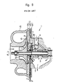
- the driving shaft 3 is lubricated with an oil introduced from an opening 6. After the lubricating oil lubricates the driving shaft 3 and so forth, the oil returns from an outlet opening 7 to a crank case (not shown in drawings) of an engine 8 shown in Figure 1. However, a part of the oil happens to be suctioned by a vacuum into an intake passage 9 shown in Figure 1, thereby resulting in the consumption within the combustion chamber 5 of the engine 8. Such a vacuum is generated by a Venturi effect occurred when an air flows through a restricted passage 12 defined between a compressor housing 10 and a center housing 11, shown in Figure 9.
- a throttle valve 13 shown in Figure 1
- a vacuum occurs in the intake passage 9 according to the time delay responding to the compressor wheel 4.
- Such a consumption of the lubricating oil in the combustion chamber 5 is not preferable from the standpoint that the consumption of the lubricating oil causes an unusual combustion within the engine 8, the occurrence of a white smoke, and a decrease in a lubricating oil.
- a conventional turbocharger 1 includes a lubricating oil sealing apparatus 17 as shown in Figure 9.
- This lubrication oil sealing apparatus 17 comprises a sealing collar 14, a retainer 15, and a deflector 16.
- the sealing collar 14 is fitted with some amount of pressure into the driving shaft 3.
- the retainer 15 is mounted on the center housing 11.
- the deflector 16 is mounted between the retainer 15 and a thrust bearing 19.
- the sealing collar 14 includes a sealing ring 27 thereon.
- the sealing collar 14 has a radial projection 18 which is a form of a disc plate. The projection 18 extends in a parallel relationship with the retainer 15 with a small clearance t 1 .
- the projection 18 extends in a parallel relationship with the deflector 16 with a small clearance t 2 .
- the lubricating oil sealing apparatus 17 prevents the oil from being suctioned into the intake passage 9 by the effect of a labyrinth mechanism and further by the use of the sealing ring 27.
- the thrust bearing 19 is mounted on the driving shaft 3 in the condition shown in Figure 10.
- a thrust collar 20 is fitted with some amount of pressure onto the driving shaft 3.
- the deflector 16 is attached to the side wall of the thrust bearing 19.
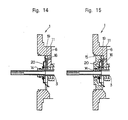
- the sealing collar 14 is fitted with some amount of pressure on the driving shaft 3, as shown in Figure 14.
- the retainer 15 is mounted on the outer peripheral portion of the sealing collar 14, and the deflector 16 is held between the retainer 15 and the thrust bearing 19.
- a stop ring 24 fastens the retainer 15 to the center housing 11.
- DE-A-2,853,525 describes a lubricating oil sealing apparatus assembled in a turbocharger in accordance with the preamble of the present Claim 1.
- the present invention was made in view of the foregoing background and to overcome the foregoing drawbacks. It is accordingly an object of this invention to provide an improved method of assembling a lubricating oil sealing apparatus in a turbocharger allowing the assembly to be made in a relatively short period of time.
- the invention provides a method of assembling a lubricating oil sealing apparatus in a turbocharger, the lubricating oil sealing apparatus being for use in a turbocharger equipped with a compressor wheel for supplying supercharged air.
- a turbocharger equipped with a compressor wheel for supplying supercharged air.
- the sealing collar comprising a main body portion which has a hole therein so that the driving shaft may extend therethrough and a radially outwardly extending projection, a retainer surrounding the sealing collar, and a deflector which has a hole therein so that the sealing collar may extend therethrough, the hole of the deflector having a diameter larger than the outside diameter of the sealing collar and less then the outside diameter of the radially extended projection of the sealing collar, the deflector being secured onto the retainer, and a resilient means provided between an inside portion of the retainer and an outside portion of the
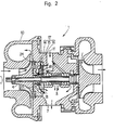
- Figure 2 illustrates a longitudinal cross-sectional view of a turbocharger in which a lubricating oil sealing apparatus assembled in accordance with the present invention is applied.
- the lubricating oil sealing apparatus 17 comprises a sealing collar 14, a retainer 15, and a deflector 16.
- Figure 3 illustrates an enlarged longitudinal cross-sectional view of the lubricating oil sealing apparatus 17 shown in Figure 2.
- the sealing collar 14 has a radially extending projection 18 at outer periphery thereof, which is a form of a disc.
- the sealing collar 14 has a first rib 25 and a second rib 26, both of which are circular in cross-section and radially extend in a parallel relationship with each other.
- the seal ring 27 is designed to have an outside diameter D1 greater than an outside diameter D2 of the first and second ribs 25 and 26.
- the sealing collar 14 has a hole 28 which axially extends therein, for allowing the driving shaft 3 to extend therein.
- Figure 5 illustrates a longitudinal cross-sectional view of a retainer 15 which is employed in an assembly in accordance with the present invention.
- the retainer 15 has a hole 29 at center thereof, in which the driving shaft 3 axially extends.
- An inside diameter d 1 of the hole 29 of the retainer 15 is designed to be slightly smaller than the outside diameter D1 of the seal ring 27 shown in Figure 3.
- the retainer 15 has a stepped portion 33 adjacent to outer periphery thereof, on which the deflector 16 is fitted.
- FIG 4 illustrates a longitudinal cross-sectional view of the deflector 16 which is employed in an assembly in accordance with the present invention.
- the deflector 16 has a form of a disc and is provided with a circular opening 30 at center thereof.
- An inside diameter d 2 of the opening 30 is designed to be greater than the outside diameter D3 of the sealing collar 14 shown in Figure 3 and to be less than the outside diameter D4 of the projection 18.
- the deflector 16 has a flange portion 31, which radially and obliquely extends, guides the lubricating oil returned to the outlet opening 7.
- the outside diameter d 4 of the deflector 16 is designed to be almost same as or slightly greater than the inside diameter d 3 of the stepped portion 33 of the retainer 15 shown in Figure 5.
- the sealing collar 14, the retainer 15, and the deflector 16 are assembled into one assembly by the following procedure. Firstly, the seal ring 27 is fitted into the groove defined between the first and second ribs 25 and 26 of the sealing collar 14. Next, while the seal ring 27 is held in the groove of the sealing collar 14, the sealing collar 14 is inserted into the hole 29 of the retainer 15, as shown in Figure 6. As the outside diameter D1 of the seal ring 27 is designed to be slightly greater than the inside diameter d 1 of the hole 29, the outside diameter D1 of the seal ring 27 is forced to be contracted by the distance substracted d i from D1. Hence, the sealing collar 14 is retained to the retainer 15 by the resilient force of the seal ring 27.
- the projection 18 of the sealing collar 14 radially extends in a nearly parallel relationship with the retainer 15 with a short clearance t 1 between the projection 18 and the retainer 15.
- the deflector 16 is press fitted into a stepped portion 33 of the retainer 15, and is secured to the stepped portion 33 with an impact force in the direction B shown in Figure 3.
- the deflector 16 is subjected to a small amount of a plastic deformation in the direction C shown in Figure 3. This results in the deflector 16 being secured to the stepped portion 33 of the retainer 15.
- the projection 18 of the sealing collar 14 radially extends in a nearly parallel relationship with the deflector 16, and there is provided with a short clearance t 2 between the projection 18 and the deflector 16, as shown in Figure 3. Further, there is provided the short cIearan ⁇ e t ⁇ between the projection 18 and the retainer 15. Hence, a labyrinth structure is constituted between the retainer 15, the projection 18, and the deflector 16.
- the lubricating oil sealing apparatus 17 prevents the oil from being leaked into the intake passage 9 owing to the labyrinth effect and the sealing effect of the seal ring 27.
- Thus assembled lubricating oil sealing apparatus 17 is press fitted in the driving shaft 3 of the turbocharger 1.
- Figure 7 illustrates such a condition as the lubricating oil sealing apparatus 17 is press fitted into the driving shaft 3.
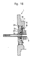
- the lubricating oil sealing apparatus 17 is mounted to the turbocharger 1 by the way that the stop ring 24 secures the retainer 15 onto the center housing 11. Further, a compressor wheel and a compressor housing are mounted on the lubricating oil sealing apparatus shown in Figure 8, and the assembly of a turbocharger is completed.
- the lubricating oil sealing apparatus 17 is assembled in accordance with the present embodiment, into one body in advance. If the assembled body is mounted on a turbocharger, the assembly of the lubricating oil sealing apparatus is completed.
Landscapes
- Engineering & Computer Science (AREA)
- Mechanical Engineering (AREA)
- General Engineering & Computer Science (AREA)
- Supercharger (AREA)
- Sealing Using Fluids, Sealing Without Contact, And Removal Of Oil (AREA)
Claims (5)
Applications Claiming Priority (2)
| Application Number | Priority Date | Filing Date | Title |
|---|---|---|---|
| JP106636/83 | 1983-07-08 | ||
| JP1983106636U JPS6014246U (ja) | 1983-07-08 | 1983-07-08 | タ−ボチヤ−ジヤのオイル洩れ防止装置 |
Publications (3)
| Publication Number | Publication Date |
|---|---|
| EP0131402A2 EP0131402A2 (de) | 1985-01-16 |
| EP0131402A3 EP0131402A3 (en) | 1985-03-06 |
| EP0131402B1 true EP0131402B1 (de) | 1988-04-27 |
Family
ID=14438598
Family Applications (1)
| Application Number | Title | Priority Date | Filing Date |
|---|---|---|---|
| EP84304208A Expired EP0131402B1 (de) | 1983-07-08 | 1984-06-21 | Verfahren zum Montieren einer Vorrichtung für Schmierölabdichtung in einem Turbolader |
Country Status (4)
| Country | Link |
|---|---|
| US (1) | US4523763A (de) |
| EP (1) | EP0131402B1 (de) |
| JP (1) | JPS6014246U (de) |
| DE (1) | DE3470771D1 (de) |
Families Citing this family (17)
| Publication number | Priority date | Publication date | Assignee | Title |
|---|---|---|---|---|
| JPS6111423A (ja) * | 1984-06-28 | 1986-01-18 | Taiho Kogyo Co Ltd | タ−ボチヤ−ジヤ用非接触型シ−ル装置 |
| GB9222133D0 (en) * | 1992-10-21 | 1992-12-02 | Leavesley Malcolm G | Turbocharger apparatus |
| JPH09264151A (ja) * | 1996-03-29 | 1997-10-07 | Aisin Seiki Co Ltd | ターボチャージャのオイル漏れ防止機構 |
| US6264203B1 (en) * | 1999-01-29 | 2001-07-24 | Mpr Associates, Inc. | Methods and apparatus for repairing a cracked jet pump riser in a boiling water reactor utilizing a spacer camp |
| KR101182122B1 (ko) * | 2008-04-08 | 2012-09-13 | 가부시키가이샤 아이에이치아이 | 터보 챠저 |
| DE102009058068A1 (de) * | 2009-12-14 | 2011-06-16 | Bosch Mahle Turbo Systems Gmbh & Co. Kg | Lagergehäuse einer Ladeeinrichtung |
| DE102010003796A1 (de) | 2010-04-09 | 2011-10-13 | Abb Turbo Systems Ag | Wellenabdichtung |
| US8991175B2 (en) * | 2012-03-28 | 2015-03-31 | GM Global Technology Operations LLC | Control of balance drift in turbocharger rotating assembly |
| EP2872753B1 (de) * | 2012-07-15 | 2019-03-20 | Garrett Transportation I Inc. | Turbolader mit einem schmiermitteldeflektor |
| DE102013005167B3 (de) * | 2013-03-26 | 2014-09-11 | Borgwarner Inc. | Abgasturbolader |
| US9771946B2 (en) | 2014-08-01 | 2017-09-26 | Caterpillar Inc. | Turbocharger compressor oil deflector and method |
| JP5964378B2 (ja) * | 2014-10-03 | 2016-08-03 | 三菱重工業株式会社 | 過給機 |
| US9638203B2 (en) * | 2015-09-15 | 2017-05-02 | Borgwarner Inc. | Bearing housing |
| WO2017170753A1 (ja) * | 2016-03-31 | 2017-10-05 | 株式会社Ihi | 過給機 |
| GB2603074B (en) * | 2019-08-28 | 2023-05-31 | Cummins Ltd | Baffle element, diffuser plate and seal system incorporating a baffle element and a diffuser plate |
| CN112780400B (zh) * | 2021-03-04 | 2022-09-13 | 北京理工大学 | 航空活塞发动机高空功率恢复专用增压器 |
| JP7460018B2 (ja) * | 2021-04-23 | 2024-04-02 | 株式会社Ihi | 過給機 |
Family Cites Families (11)
| Publication number | Priority date | Publication date | Assignee | Title |
|---|---|---|---|---|
| US2936715A (en) * | 1955-11-14 | 1960-05-17 | Thompson Ramo Wooldridge Inc | Seal assembly |
| US2925290A (en) * | 1956-05-16 | 1960-02-16 | Garrett Corp | Self-equalizing seal for a rotating shaft |
| GB831770A (en) * | 1957-06-20 | 1960-03-30 | United Aircraft Corp | Compressor-turbine unit |
| US3519277A (en) * | 1968-01-18 | 1970-07-07 | Pneumo Dynamics Corp | Fan seal |
| US4018059A (en) * | 1975-04-30 | 1977-04-19 | General Electric Company | Cryogenic fluid transfer joint employing gaseous seals |
| US4114059A (en) * | 1976-09-03 | 1978-09-12 | Westinghouse Electric Corp. | Grooved visco seal for stationary discharge chamber of water-cooled turbine generator |
| GB1574942A (en) * | 1977-04-20 | 1980-09-10 | Komatsu Mfg Co Ltd | Centrifugal compressor combines with a turbine |
| DE2853525A1 (de) * | 1978-12-12 | 1980-06-26 | Audi Nsu Auto Union Ag | Turbolader |
| JPS5783632A (en) * | 1980-11-12 | 1982-05-25 | Yamaha Motor Co Ltd | Bearing structure of turbo-supercharger |
| US4364241A (en) * | 1980-12-02 | 1982-12-21 | Mitsubishi Denki Kabushiki Kaisha | Device for draining cooling liquid from rotary electric machine with liquid cooled rotor |
| JPS5815721A (ja) * | 1981-07-22 | 1983-01-29 | Taiho Kogyo Co Ltd | タ−ボチヤ−ジヤの給油装置 |
-
1983
- 1983-07-08 JP JP1983106636U patent/JPS6014246U/ja active Pending
-
1984
- 1984-06-21 EP EP84304208A patent/EP0131402B1/de not_active Expired
- 1984-06-21 DE DE8484304208T patent/DE3470771D1/de not_active Expired
- 1984-07-03 US US06/627,660 patent/US4523763A/en not_active Expired - Lifetime
Also Published As
| Publication number | Publication date |
|---|---|
| EP0131402A2 (de) | 1985-01-16 |
| EP0131402A3 (en) | 1985-03-06 |
| US4523763A (en) | 1985-06-18 |
| DE3470771D1 (en) | 1988-06-09 |
| JPS6014246U (ja) | 1985-01-30 |
Similar Documents
| Publication | Publication Date | Title |
|---|---|---|
| US4523763A (en) | Turbocharger lubricating oil sealing method | |
| US5076766A (en) | Turbocharger bearing retention and lubrication system | |
| EP1387061B1 (de) | Ölabdichtung eines Turboladers | |
| US5145334A (en) | Turbocharger bearing retention and lubrication system | |
| KR20020077259A (ko) | 오일 제어 장치 | |
| EP0357246B1 (de) | Wellendichtungseinrichtung für Turbolader | |
| US4436067A (en) | Engine driven pump arrangement | |
| US5066192A (en) | Oil sealing system for a turbo charger | |
| US10982687B2 (en) | Housing for turbocharger and method for manufacturing the same | |
| US4198063A (en) | Shaft sealing device for turbocharger | |
| US20180252229A1 (en) | Housing for turbocharger and method for manufacturing the same | |
| US20160097293A1 (en) | Compressor seal assembly for a turbocharger | |
| US6200089B1 (en) | Coolant pump | |
| US7186081B2 (en) | Air turbine starter enhancement for clearance seal utilization | |
| EP0528004B1 (de) | Hydraulische pumpe für fahrzeugmotor | |
| US4624629A (en) | Lubrication mechanism for a turbocharger | |
| US6338614B1 (en) | Turbocharger annular seal gland | |
| GB2223274A (en) | Driving pumps | |
| JPS6038592B2 (ja) | 高速回転機器の従動機器側シ−ル構造 | |
| US4650398A (en) | Bearing unit with integrated pump | |
| JPH0639067Y2 (ja) | ガスタービンの軸受部潤滑構造 | |
| JP2003049851A (ja) | 転がり軸受のエアオイル潤滑装置 | |
| GB2583181A (en) | Assembly for a turbomachine | |
| CN216157778U (zh) | 一种前端盖及发动机 | |
| JPH05280366A (ja) | ターボチャージャのオイルシール構造 |
Legal Events
| Date | Code | Title | Description |
|---|---|---|---|
| PUAI | Public reference made under article 153(3) epc to a published international application that has entered the european phase |
Free format text: ORIGINAL CODE: 0009012 |
|
| PUAL | Search report despatched |
Free format text: ORIGINAL CODE: 0009013 |
|
| AK | Designated contracting states |
Designated state(s): DE FR GB |
|
| AK | Designated contracting states |
Designated state(s): DE FR GB |
|
| 17P | Request for examination filed |
Effective date: 19850207 |
|
| GRAA | (expected) grant |
Free format text: ORIGINAL CODE: 0009210 |
|
| AK | Designated contracting states |
Kind code of ref document: B1 Designated state(s): DE FR GB |
|
| REF | Corresponds to: |
Ref document number: 3470771 Country of ref document: DE Date of ref document: 19880609 |
|
| ET | Fr: translation filed | ||
| PLBE | No opposition filed within time limit |
Free format text: ORIGINAL CODE: 0009261 |
|
| STAA | Information on the status of an ep patent application or granted ep patent |
Free format text: STATUS: NO OPPOSITION FILED WITHIN TIME LIMIT |
|
| 26N | No opposition filed | ||
| REG | Reference to a national code |
Ref country code: GB Ref legal event code: 746 |
|
| REG | Reference to a national code |
Ref country code: FR Ref legal event code: DL |
|
| REG | Reference to a national code |
Ref country code: GB Ref legal event code: IF02 |
|
| PGFP | Annual fee paid to national office [announced via postgrant information from national office to epo] |
Ref country code: FR Payment date: 20020610 Year of fee payment: 19 |
|
| PGFP | Annual fee paid to national office [announced via postgrant information from national office to epo] |
Ref country code: GB Payment date: 20020619 Year of fee payment: 19 |
|
| PGFP | Annual fee paid to national office [announced via postgrant information from national office to epo] |
Ref country code: DE Payment date: 20020626 Year of fee payment: 19 |
|
| PG25 | Lapsed in a contracting state [announced via postgrant information from national office to epo] |
Ref country code: GB Free format text: LAPSE BECAUSE OF NON-PAYMENT OF DUE FEES Effective date: 20030621 |
|
| PG25 | Lapsed in a contracting state [announced via postgrant information from national office to epo] |
Ref country code: DE Free format text: LAPSE BECAUSE OF NON-PAYMENT OF DUE FEES Effective date: 20040101 |
|
| GBPC | Gb: european patent ceased through non-payment of renewal fee |
Effective date: 20030621 |
|
| PG25 | Lapsed in a contracting state [announced via postgrant information from national office to epo] |
Ref country code: FR Free format text: LAPSE BECAUSE OF NON-PAYMENT OF DUE FEES Effective date: 20040227 |
|
| REG | Reference to a national code |
Ref country code: FR Ref legal event code: ST |