EP0131632B1 - Moteur triphase sans balais - Google Patents
Moteur triphase sans balais Download PDFInfo
- Publication number
- EP0131632B1 EP0131632B1 EP84900306A EP84900306A EP0131632B1 EP 0131632 B1 EP0131632 B1 EP 0131632B1 EP 84900306 A EP84900306 A EP 84900306A EP 84900306 A EP84900306 A EP 84900306A EP 0131632 B1 EP0131632 B1 EP 0131632B1
- Authority
- EP
- European Patent Office
- Prior art keywords
- brushless motor
- rotor
- phase brushless
- transducer elements
- electromagnetic transducer
- Prior art date
- Legal status (The legal status is an assumption and is not a legal conclusion. Google has not performed a legal analysis and makes no representation as to the accuracy of the status listed.)
- Expired
Links
Images


Classifications
-
- H—ELECTRICITY
- H02—GENERATION; CONVERSION OR DISTRIBUTION OF ELECTRIC POWER
- H02K—DYNAMO-ELECTRIC MACHINES
- H02K29/00—Motors or generators having non-mechanical commutating devices, e.g. discharge tubes or semiconductor devices
- H02K29/06—Motors or generators having non-mechanical commutating devices, e.g. discharge tubes or semiconductor devices with position sensing devices
- H02K29/08—Motors or generators having non-mechanical commutating devices, e.g. discharge tubes or semiconductor devices with position sensing devices using magnetic effect devices, e.g. Hall-plates, magneto-resistors
-
- H—ELECTRICITY
- H02—GENERATION; CONVERSION OR DISTRIBUTION OF ELECTRIC POWER
- H02K—DYNAMO-ELECTRIC MACHINES
- H02K29/00—Motors or generators having non-mechanical commutating devices, e.g. discharge tubes or semiconductor devices
Definitions
- FIG. 1 So far flat and small three-phase brushless motor has been proposed as shown in Fig. 1.
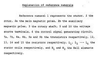
- reference numeral 1 designates a stator, 2 a rotor and 3 a rotary shaft.
- This stator 1 comprises six flat stator coils L I , L 2 ... L 6 which are disposed on a base plate 4 of nearly circular shape with an equal angular range, for example, an angular range of 60° as shown in Fig. 2.
- a pair of opposing coils L 1 and L 4 ; L 2 and L 5 ; and L 3 and L 6 are respectively connected in series or in parallel to each other.
- the rotor 2 is formed of a magnet or disk shape in which eight poles of N poles and S poles are alternately magnetized with an equal angular range as, for example, shown in Fig. 3.
- electromagnetic transducer elements for example, Hall elements H 1 , H 2 and H 3 are respectively disposed on the base plate of the stator 1 at its predetermined position, for example, at the intermediate position between the stator coils L 6 and L I , at the intermediate position between the stator coils L 1 and L 2 and at the intermediate position between the stator coils L 2 and L 3 on the external peripheral portion of the base plate of the stator 1.
- the geometrical angle between adjacent Hall elements H 1 , H 2 and H 3 is 60°
- the Hall elements are disposed with a relative positional relation of an electrical angle of 240°.
- each of the Hall elements H I , H 2 and H 3 is connected between a voltage source terminal 5 and the ground.
- the output signals from the Hall elements H 1 , H 2 and H 3 are respectively supplied to a control signal generating circuit 6 which is formed of a semiconductor integrated circuit.
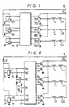
- the six output terminals of the control signal generating circuit 6 are respectively connected to bases of npn-transistors 7a, 7b, 8a, 8b, 9a and 9b.
- the collectors of the respective transistors 7a, 8a and 9a are connected together to a voltage source terminal 10 to which a positive D.C. voltage is supplied.
- the emitters of the transistors 7a, 8a and 9a are respectively connected to the collectors of the transistors 7b, 8b and 9b and the emitters of these transistors 7b, 8b and 9b are respectively grounded.
- the connection point between the emitter of the transistor 7a and the collector of the transistor 7b is connected through a series circuit formed of a series circuit of the stator coils L 1 and L 4 and a series circuit of the stator coils L 5 and L 2 to the connection point between the emmitter of the transistor 8a and the collector of the transistor 8b.
- connection point between the stator coils L 4 and L s is connected through a series circuit of the stator coils L 6 and L 3 to the connection point between the emitter of the transistor 9a and the collector of the transistor 9b.
- the Hall elements H 1 , H 2 and H 3 produce at their output terminals square wave signal having phases each of which is sequentially different from one another by an electrical angle of 240° as shown in Figs.
- control signal generating circuit 6 if a current flowing through the series circuit of the stator coils L 1 , and L 4 is taken as la, a current flowing through the series circuit of the stator coils L 2 and L s as Ib and a current flowing through the series circuit of the stator coils L 3 and L 6 as Ic, the control signal generating circuit 6 is so formed that it generates control signals such that, as shown in Figs.
- these currents la, Ib and Ic have different phases by 120° each and each of them becomes a positive current during 120° of the electrical angle, a zero current during the succeeding 60° of the electrical angle, a negative current during the succeeding 120° of the electrical angle and a zero current during the succeeding 60° of the electrical angle, respectively, which is repeated sequentially.
- a three-phase brushless motor is previously proposed in which two electromagnetic transducer elements, for example, two Hall elements H, and H 2 for detecting the rotation position of the rotor 2 are respectively disposed with a relative positional relation having an electrical angle of 120° or 240° and the output signals of the electromagnetic transducer elements H, and H 2 are composed with each other to thereby produce a composed signal having a phase difference of 120° relative to the output signals of the electromagnetic transducer elements H, and H 2 so that on the basis of the composed signal and the output signals from the electromagnetic transducer elements H 1 and H 2 , the drive currents are supplied to the stator coils L I , L 2 ... L s .
- two electromagnetic transducer elements for example, two Hall elements H, and H 2 for detecting the rotation position of the rotor 2 are respectively disposed with a relative positional relation having an electrical angle of 120° or 240° and the output signals of the electromagnetic transducer elements H, and H 2 are composed with each other to thereby produce a composed signal having
- the stator 1 and the rotor 2 are formed similarly to those shown in Figs. 2 and 3, in which of the Hall elements H I , H 2 and H 3 as shown in Fig. 2, the Hall element H 3 is removed, while the two Hall elements H 1 and H 2 are provided.
- each of the Hall elements H 1 and H 2 is disposed to have a relative positional relation with an electrical angle of 240°.
- connection point between the resistors 12 and 13 is connected to a sixth input terminal of the control signal generating circuit 6.
- a series circuit which is formed of two resistors 14 and 15, each resistor having an equal resistance value R.
- the connection point between the resistors 14 and 15 is connected to a fifth input terminal of the control signal generating circuit.
- the resistance value R of each of the resistors 12, 13, 14 and 15 is selected extremely larger than those of the Hall elements H 1 and H 2 .
- the detecting signals such as shown in Figs. 5A, 5B and 5C are respectively supplied to the input terminals of the control signal generating circuit 6.
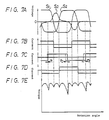
- the other circuit portions are constructed similarly to those of Fig. 4 so that by the circuit shown in Fig. 6, the rotor 2 can be rotated similarly to that shown in Fig. 4.
- the number of Hall elements can be reduced from three to two, the number of the wires for interconnecting the Hall elements with the drive circuit can be reduced and the power consumption can also be reduced, which facts are advantageous for miniaturizing the motor.
- Figs. 7C being applied between the fifth and sixth input terminals of the control signal generating circuit 6.
- the composed signal c shown in Fig. 7C is such one that the phases of the falling edges and the rising edges of the square wave are displaced from the normal phases by ⁇ 1 , ⁇ 2 , ⁇ 3 ....
- Figs. 7B and 7D respectively show waveforms which are obtained from the output signals S, and S 2 of the Hall elements H, and H 2 .
- the signals as shown in Figs. 7B, 7C and 7D are respectively supplied to the input terminals of the control signal generating circuit 6 so as to produce the drive currents which are supplied to the stator coils L I , L2...
- the present invention is to improve uneven rotation torque of a three-phase brushless motor which uses two electromagnetic transducer elements.
- the present invention is to provide a three-phase brushless motor in which two electromagnetic transducer elements for detecting the rotation position of a rotor having a plurality of magnetized areas are disposed to have a relative positional relation with an electrical angle of 120° or 240°, a composed signal having a phase difference of 120° relative to the output signals from the electromagnetic transducer elements is produced, and the drive currents supplied to stator coils are determined by the composed signal and the output signals from the electromagnetic transducer elements.
- an auxiliary magnetic pole having opposite polarity to that of the main magnetic pole is disposed on the rotor at a portion near and opposing to the electromagnetic transducer elements so as to make the waveform of the composed signal of the output signals from the electromagnetic transducer elements steep at zero-cross points of the waveform of the composed signal.
- Fig. 1 is a cross-sectional view showing an example of a three-phase brushless motor of a flat type
- Fig. 2 is a plan view showing an example of a prior art stator
- Fig. 3 is a plan view showing an example of a prior art rotor
- Fig.s 4 and are respectively diagrams showing examples of a drive current supplying circuit
- Figs. 5, 7, 9 and 11 are respectively diagrams useful for explaining the present invention
- Fig. 8 is a plan view showing an example of a rotor used in an embodiment of a three-phase brushless motor according to the present invention
- Figs. 10 and 12 are respectively plan views showing examples of rotors used in other embodiments of the present invention
- Fig. 13 is a diagram showing an example of a rotor in a case wherein the present invention is applied to a cylindrical type motor.
- FIG. 8 An embodiment of a three-phase brushless motor according to the present invention will hereinafter be described with reference to Fig. 8.
- like parts corresponding to those in Fig. 3 are marked with the same references and their detailed description will be omitted.
- the stator 1 is formed such that as shown in Fig. 2, six flat stator coils L 1 , L 2 ... L 6 are disposed on the base plate 4 of substantially circular shape with an equal angular range, for example, an angular range of 60°.
- the opposing stator coils L 1 and L 4 ; L 2 and L s ; and L 3 and L 6 are respectively coupled serially or parallerlly to each other.
- the electromagnetic transducer elements for example, Hall elements H 1 and H 2 are respectively disposed at predetermined positions of the stator 1, for example, at the intermediate position between the stator coils L 6 and L I and at the intermediate position between the stator coils L, and L 2 in the external peripheral portion of the stator 1.
- each of the Hall elements H, and H 2 are disposed to have a relative positional relation with an electrical angle of 240°.
- the connection relation among the Hall elements H 1 , H 2 and the stator coils L 1 , L2... L 6 is made the same as that in Fig. 6.
- the rotor 2 is constructed as shown in Fig. 8. That is, the rotor 2 is formed such that for example, 8 poles of N poles and S poles are alternately magnetized on a disk made of magnetic material with an equal angular spacing as main magnetic poles 2a and auxiliary magnetic poles 2b having opposite polarities to those of the main magnetic poles 2a are magnetized on the disk at its external peripheral portions defined by connecting adjacent intermediate points of the 8 main magnetic poles 2a.
- the auxiliary magnetic poles 2b of the rotor 2 are arranged to substantially pass over the electromagnetic transducer element H, and H 2 of the stator.
- the two Hall elements H 1 and H 2 for detecting the rotation position of the rotor 2 are disposed to have a relative positional relation with an electrical angle of 240°, the output signals from the Hall elements H 1 and H 2 are composed to each other so as to produce a composed signal which has a phase difference of 120° relative to the output signals from the Hall elements H 1 and H 2 , and the composed signal and the output signals from the Hall elements H, and H 2 are used to determine the drive currents which will be fed to the stator coils L 1 , L 2 ... L 6 .
- the composed signal and the output signals from the Hall elements H, and H 2 are used to determine the drive currents which will be fed to the stator coils L 1 , L 2 ... L 6 .
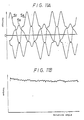
- the waveforms of the output signals from the Hall elements H, and H 2 are not saturated and become relatively steep waveforms as shown curves S 4 and S 5 in Fig. 9A because of the auxiliary magnetic poles 2b of opposite polarities to those of the main magnetic poles 2a provided on the portions of rotor 2 near end opposing to the Hall elements H 1 and H 2 .
- a waveform S 6 of the composed signal c formed on the basis of the waveforms S 4 and S s becomes relatively steep at zero-cross points as shown in Fig. 9A and hence the zero-cross points are determined.
- the composed signal c as shown in Fig.
- Fig. 9C is supplied between the fifth and six input terminals of the control signal generating circuit 6.
- the rising edge and the falling edge of its square wave are determined by the zero-cross points of the waveform S 6 .
- Figs. 9B and 9D respectively show the waveforms provided from the output signals S 4 and S s of the Hall elements H, and H 2 .
- the signals as shown in Figs. 9B, 9C and 9D are supplied to the input terminals of the control signal generating circuit 6 which then produces the drive currents to be supplied to the stator coils L 1 , L 2 ... L 6 and the rotor 2 is rotated by the above drive currents, its uneven rotation torque becomes relatively small as shown in Fig. 9E and a ripple can be reduced to, for example, 6.3%.
- Fig. 10 shows another embodiment of the rotor 2 according to the present invention.
- two auxiliary magnetic poles 2b of island shape having opposite polarities to those of the main magnetic poles 2a are symmetrically disposed near the external peripheries of the main magnetic poles 2a.
- the auxiliary magnetic poles 2b of the island shape are respectively provided to have electrical angles of substantially 60°, 120°, 240° and 300° as shown in Fig. 10.
- the waveforms of the output signals from the Hall elements H, and H 2 become as shown by curves S 7 and S 8 in Fig. 11A.
- Fig. 12 shows a further embodiment of the present invention, and in the embodiment of Fig. 12, the auxiliary magnetic poles 2b of the rotor 2 are respectively disposed at the inside of the main magnetic poles 2a.
- the Hall elements H, and H 2 of the stator are disposed so as to correspond to the auxiliary magnetic poles 2b, too.
- the rotor thereof is constructed as shown in Figs. 13A and 13B, in which the auxiliary magnetic poles 2b are disposed on the end surface of the rotor. According to the embodiment shown in Fig. 13, similar action and effect as above can be of course achieved.
- the Hall element in the above embodiments, other electromagnetic transducer element such as magneto- resistance element and so on can be used.
- the two electromagnetic transducer elements are disposed to have an electrical angular spacing of 240° therebetween, it will be easily understood that they can be disposed to have an electrical angular spacing of 120°.
Landscapes
- Engineering & Computer Science (AREA)
- Power Engineering (AREA)
- Brushless Motors (AREA)
- Control Of Motors That Do Not Use Commutators (AREA)
- Permanent Field Magnets Of Synchronous Machinery (AREA)
Abstract
Claims (7)
Priority Applications (1)
| Application Number | Priority Date | Filing Date | Title |
|---|---|---|---|
| AT84900306T ATE26048T1 (de) | 1983-01-14 | 1983-12-28 | Buerstenfreier dreiphasenmotor. |
Applications Claiming Priority (2)
| Application Number | Priority Date | Filing Date | Title |
|---|---|---|---|
| JP4517/83 | 1983-01-14 | ||
| JP58004517A JPH0622394B2 (ja) | 1983-01-14 | 1983-01-14 | 3相ブラシレスモータ |
Publications (3)
| Publication Number | Publication Date |
|---|---|
| EP0131632A1 EP0131632A1 (fr) | 1985-01-23 |
| EP0131632A4 EP0131632A4 (fr) | 1985-07-01 |
| EP0131632B1 true EP0131632B1 (fr) | 1987-03-18 |
Family
ID=11586240
Family Applications (1)
| Application Number | Title | Priority Date | Filing Date |
|---|---|---|---|
| EP84900306A Expired EP0131632B1 (fr) | 1983-01-14 | 1983-12-28 | Moteur triphase sans balais |
Country Status (6)
| Country | Link |
|---|---|
| US (1) | US4585979A (fr) |
| EP (1) | EP0131632B1 (fr) |
| JP (1) | JPH0622394B2 (fr) |
| KR (1) | KR910000093B1 (fr) |
| DE (1) | DE3370417D1 (fr) |
| WO (1) | WO1984002810A1 (fr) |
Families Citing this family (17)
| Publication number | Priority date | Publication date | Assignee | Title |
|---|---|---|---|---|
| US4639648A (en) * | 1983-01-14 | 1987-01-27 | Sony Corporation | Three-phase brushless motor |
| DE3435270A1 (de) * | 1984-09-26 | 1986-04-03 | Deutsche Thomson-Brandt Gmbh, 7730 Villingen-Schwenningen | Verfahren zum anlaufen eines elektronisch kommutierten gleichstrommotors |
| JPS61135352A (ja) * | 1984-12-03 | 1986-06-23 | Matsushita Electric Ind Co Ltd | ブラシレス直流モ−タ |
| CH670018A5 (en) * | 1985-08-21 | 1989-04-28 | Studer Willi Ag | Collectorless DC motor using permanent magnet rotor - has alternating rotor poles arranged in two peripheral paths containing related pole numbers |
| JPS62201048A (ja) * | 1986-02-27 | 1987-09-04 | Sony Corp | 二相ブラシレスモ−タ |
| US4694210A (en) * | 1986-07-31 | 1987-09-15 | General Motors Corporation | Brushless DC motor and sensorless drive arrangement therefor |
| JPH01278247A (ja) * | 1988-04-30 | 1989-11-08 | Fanuc Ltd | 同期電動機 |
| JPH02231951A (ja) * | 1989-03-01 | 1990-09-13 | Sony Corp | ブラシレスモータ |
| US5017867A (en) * | 1989-12-08 | 1991-05-21 | Magnetek Controls | Magnetostrictive linear position detector with reflection termination |
| DE4232850B4 (de) * | 1991-09-30 | 2008-10-30 | Papst Licensing Gmbh & Co. Kg | Flachbauender, bürstenloser Gleichstrommotor zum Antrieb eines Kleingebläses |
| US6703757B2 (en) * | 1995-09-13 | 2004-03-09 | Delta Electronics Inc. | Motor structure having low profile |
| DE19650908A1 (de) * | 1995-12-22 | 1997-06-26 | Papst Motoren Gmbh & Co Kg | Elektronisch kommutierter Motor |
| KR100312293B1 (ko) * | 1998-12-28 | 2001-12-28 | 김병규 | 단일홀소자를갖는2상비엘디씨모터 |
| JP5764929B2 (ja) * | 2010-04-14 | 2015-08-19 | 株式会社安川電機 | 直動回転アクチュエータ |
| US10148152B2 (en) | 2015-02-10 | 2018-12-04 | Cts Corporation | Axial brushless DC motor |
| US10454403B2 (en) | 2016-02-05 | 2019-10-22 | Cts Corporation | Axial brushless DC motor with fractional and hold step function |
| JP2025093195A (ja) * | 2023-12-11 | 2025-06-23 | 株式会社デンソー | ブラシレスモータ |
Citations (2)
| Publication number | Priority date | Publication date | Assignee | Title |
|---|---|---|---|---|
| JPS4712408U (fr) * | 1971-03-12 | 1972-10-14 | ||
| JPS5441406A (en) * | 1977-07-04 | 1979-04-02 | Papst Motoren Kg | Motor |
Family Cites Families (7)
| Publication number | Priority date | Publication date | Assignee | Title |
|---|---|---|---|---|
| JPS5812838B2 (ja) * | 1974-09-07 | 1983-03-10 | 日本ビクター株式会社 | チヨクリユウブラシレスモ−タ |
| US4039912A (en) * | 1974-10-30 | 1977-08-02 | Victor Company Of Japan, Limited | Three-phase brushless dc motor using two hall effect devices |
| JPS54111609A (en) * | 1978-02-20 | 1979-09-01 | Sony Corp | Dc motor |
| GB1604121A (en) * | 1977-04-08 | 1981-12-02 | Sony Corp | Dc motors |
| NL7908926A (nl) * | 1979-12-12 | 1980-09-30 | Oce Nederland Bv | Belichtingsinrichting. |
| US4405885A (en) * | 1980-07-23 | 1983-09-20 | Matsushita Electric Industrial Co., Ltd. | Brushless dc motor |
| JPS57206263A (en) * | 1981-06-10 | 1982-12-17 | Sony Corp | Two phase switching type brushless motor |
-
1983
- 1983-01-14 JP JP58004517A patent/JPH0622394B2/ja not_active Expired - Lifetime
- 1983-12-28 US US06/654,004 patent/US4585979A/en not_active Expired - Lifetime
- 1983-12-28 EP EP84900306A patent/EP0131632B1/fr not_active Expired
- 1983-12-28 DE DE8484900306T patent/DE3370417D1/de not_active Expired
- 1983-12-28 WO PCT/JP1983/000463 patent/WO1984002810A1/fr not_active Ceased
-
1984
- 1984-01-05 KR KR1019840000011A patent/KR910000093B1/ko not_active Expired
Patent Citations (2)
| Publication number | Priority date | Publication date | Assignee | Title |
|---|---|---|---|---|
| JPS4712408U (fr) * | 1971-03-12 | 1972-10-14 | ||
| JPS5441406A (en) * | 1977-07-04 | 1979-04-02 | Papst Motoren Kg | Motor |
Also Published As
| Publication number | Publication date |
|---|---|
| KR910000093B1 (ko) | 1991-01-19 |
| JPH0622394B2 (ja) | 1994-03-23 |
| EP0131632A1 (fr) | 1985-01-23 |
| US4585979A (en) | 1986-04-29 |
| EP0131632A4 (fr) | 1985-07-01 |
| DE3370417D1 (en) | 1987-04-23 |
| JPS59129560A (ja) | 1984-07-25 |
| KR840007650A (ko) | 1984-12-08 |
| WO1984002810A1 (fr) | 1984-07-19 |
Similar Documents
| Publication | Publication Date | Title |
|---|---|---|
| EP0131632B1 (fr) | Moteur triphase sans balais | |
| US4371817A (en) | Brushless, permanent magnet d-c pulse current controlled, essentially uniform torque dynamo electric machine, particularly motor | |
| US4639648A (en) | Three-phase brushless motor | |
| EP0234587B1 (fr) | Moteur sans balais bi-phasé | |
| KR890001476Y1 (ko) | 무정류자 전동기 | |
| GB2049322A (en) | Direct current motors | |
| JPH07194081A (ja) | モータ | |
| JPS648555B2 (fr) | ||
| CA1256152A (fr) | Moteur triphase sans balais | |
| JPH01286759A (ja) | ブラシレスモーター | |
| JPS62126889A (ja) | 三相ブラシレスモ−タの制御方法及びその方法に用いるロ−タ | |
| JP2620110B2 (ja) | ブラシレスモータ | |
| JPS6321434B2 (fr) | ||
| JPS59136058A (ja) | 3相ブラシレスモ−タ | |
| JPH0510628B2 (fr) | ||
| JP2805071B2 (ja) | 位置検出用感磁性抵抗素子センサ | |
| JPH0767262B2 (ja) | タコジェネレータ | |
| KR900003890Y1 (ko) | 1상 통전되는 브러시리스 모터 | |
| JPH082190B2 (ja) | ホ−ル素子を用いた無整流子電動機 | |
| JPS6126461A (ja) | モ−タの回転速度検出装置 | |
| JPS5935584A (ja) | 電子整流子モ−タ駆動回路 | |
| JPS6143956B2 (fr) | ||
| JPS59221619A (ja) | 光学式回転検出装置 | |
| JPH06153480A (ja) | ブラシレスモータの速度検出装置 | |
| JPS6349477B2 (fr) |
Legal Events
| Date | Code | Title | Description |
|---|---|---|---|
| PUAI | Public reference made under article 153(3) epc to a published international application that has entered the european phase |
Free format text: ORIGINAL CODE: 0009012 |
|
| AK | Designated contracting states |
Designated state(s): AT DE FR GB NL |
|
| 17P | Request for examination filed |
Effective date: 19850109 |
|
| 17Q | First examination report despatched |
Effective date: 19860612 |
|
| GRAA | (expected) grant |
Free format text: ORIGINAL CODE: 0009210 |
|
| AK | Designated contracting states |
Kind code of ref document: B1 Designated state(s): AT DE FR GB NL |
|
| REF | Corresponds to: |
Ref document number: 26048 Country of ref document: AT Date of ref document: 19870415 Kind code of ref document: T |
|
| REF | Corresponds to: |
Ref document number: 3370417 Country of ref document: DE Date of ref document: 19870423 |
|
| ET | Fr: translation filed | ||
| PLBE | No opposition filed within time limit |
Free format text: ORIGINAL CODE: 0009261 |
|
| STAA | Information on the status of an ep patent application or granted ep patent |
Free format text: STATUS: NO OPPOSITION FILED WITHIN TIME LIMIT |
|
| 26N | No opposition filed | ||
| PGFP | Annual fee paid to national office [announced via postgrant information from national office to epo] |
Ref country code: FR Payment date: 20011212 Year of fee payment: 19 Ref country code: AT Payment date: 20011212 Year of fee payment: 19 |
|
| PGFP | Annual fee paid to national office [announced via postgrant information from national office to epo] |
Ref country code: GB Payment date: 20011227 Year of fee payment: 19 |
|
| PGFP | Annual fee paid to national office [announced via postgrant information from national office to epo] |
Ref country code: NL Payment date: 20011228 Year of fee payment: 19 |
|
| REG | Reference to a national code |
Ref country code: GB Ref legal event code: IF02 |
|
| PGFP | Annual fee paid to national office [announced via postgrant information from national office to epo] |
Ref country code: DE Payment date: 20020109 Year of fee payment: 19 |
|
| PG25 | Lapsed in a contracting state [announced via postgrant information from national office to epo] |
Ref country code: GB Free format text: LAPSE BECAUSE OF NON-PAYMENT OF DUE FEES Effective date: 20021228 Ref country code: AT Free format text: LAPSE BECAUSE OF NON-PAYMENT OF DUE FEES Effective date: 20021228 |
|
| PG25 | Lapsed in a contracting state [announced via postgrant information from national office to epo] |
Ref country code: NL Free format text: LAPSE BECAUSE OF NON-PAYMENT OF DUE FEES Effective date: 20030701 Ref country code: DE Free format text: LAPSE BECAUSE OF NON-PAYMENT OF DUE FEES Effective date: 20030701 |
|
| GBPC | Gb: european patent ceased through non-payment of renewal fee |
Effective date: 20021228 |
|
| NLV4 | Nl: lapsed or anulled due to non-payment of the annual fee |
Effective date: 20030701 |
|
| PG25 | Lapsed in a contracting state [announced via postgrant information from national office to epo] |
Ref country code: FR Free format text: LAPSE BECAUSE OF NON-PAYMENT OF DUE FEES Effective date: 20030901 |
|
| REG | Reference to a national code |
Ref country code: FR Ref legal event code: ST |