EP0131742A2 - Verfahren zum Aufbringen eines Steckers am Ende eines optischen Kabels - Google Patents
Verfahren zum Aufbringen eines Steckers am Ende eines optischen Kabels Download PDFInfo
- Publication number
- EP0131742A2 EP0131742A2 EP84106576A EP84106576A EP0131742A2 EP 0131742 A2 EP0131742 A2 EP 0131742A2 EP 84106576 A EP84106576 A EP 84106576A EP 84106576 A EP84106576 A EP 84106576A EP 0131742 A2 EP0131742 A2 EP 0131742A2
- Authority
- EP
- European Patent Office
- Prior art keywords
- sleeve member
- optical connector
- fiber cable
- optical fiber
- jacket layer
- Prior art date
- Legal status (The legal status is an assumption and is not a legal conclusion. Google has not performed a legal analysis and makes no representation as to the accuracy of the status listed.)
- Withdrawn
Links
Images

Classifications
-
- G—PHYSICS
- G02—OPTICS
- G02B—OPTICAL ELEMENTS, SYSTEMS OR APPARATUS
- G02B6/00—Light guides; Structural details of arrangements comprising light guides and other optical elements, e.g. couplings
- G02B6/24—Coupling light guides
- G02B6/36—Mechanical coupling means
- G02B6/38—Mechanical coupling means having fibre to fibre mating means
- G02B6/3807—Dismountable connectors, i.e. comprising plugs
- G02B6/3833—Details of mounting fibres in ferrules; Assembly methods; Manufacture
- G02B6/3855—Details of mounting fibres in ferrules; Assembly methods; Manufacture characterised by the method of anchoring or fixing the fibre within the ferrule
- G02B6/3861—Adhesive bonding
Definitions
- the present invention relates to a method for coupling the end section of an optical fiber cable to an optical connector.
- an optical fiber cable comprises a core and a cladding with a jacket layer.
- the core comprises silica glass containing sio 2 as the major component from the viewpoint of excellent optical transmission characteristics and long-term reliability.
- the cladding may comprise silica glass, multicomponent glass, silicone resin or the like.
- the cladding is desired to be made of silicone resin in consideration of optical transmission loss of the optical fiber and fabrication cost.
- An optical fiber cable which has a silica glass core and a silicone resin cladding will be described throughout the specification.
- the exposed silicone cladding and jacket layer are adhered to the optical connector by an adhesive such as an epoxy resin.
- an adhesive such as an epoxy resin.
- the adhesion strength is decreased by thermal expansion and contraction stress of the jacket layer, because of poor adhesion between the cladding and the adhesive.
- the optical fiber cable is moved relative to the optical connector, resulting in misalignment.
- Another conventional method is proposed to prevent misalignment as described above.
- a jacket layer is peeled off from the optical fiber cable, and is not brought into contact with the optical connector to form a space corresponding to the jacket layer. Therefore, the thermal expansion and contraction stress of the jacket layer are prevented.
- this method only the exposed silicone cladding is coupled to the optical connector. The tensile strength is very small, and the optical fiber cable can be easily removed from the optical connector, resulting in inconvenience.
- Still another conventional method is proposed to further reinforce the adhesion between the silicone cladding and the adhesive.
- a jacket layer and a silicone cladding are peeled off, and another cladding adhesive to a glass core, is formed on the silica glass core.
- the end section of the optical fiber cable which is modified as described above is adhered to the optical connector.
- this method results in time-consuming handling and low reliability.
- a method for coupling the end section of an optical fiber cable to an optical connector with a through hole, the optical fiber cable having a core and a silicone cladding covered with a jacket layer comprising the steps of peeling off said jacket layer for a predetermined length from the end of said optical fiber cable along an axial direction thereof to expose said silicone cladding, inserting an exposed portion of said silicone cladding into a deformable sleeve member, and compressing said sleeve member to bring said sleeve member into tight contact with said exposed silicone cladding, and inserting said silicone cladding and a part of said jacket layer into said optical connector after an adhesive is applied to the outer surface of said sleeve member and/or the inner surface of the through hole of said optical connector, and adhering said sleeve member to said optical connector, thereby coupling the end section of said optical fiber cable to said optical connector.
- the sleeve member is brought into tight contact with the silicone cladding, and the sleeve member is secured to the optical connector by the adhesive, whereby the end section of the optical fiber cable is rigidly fixed to the optical connector.
- the silicone cladding serves as a absorbent layer when the optical fiber of a silicone cladding type is compressed, so that it will be eliminated that the silica glass core is broken.
- the sleeve member is used as a caulking member to prevent the optical fiber cable from being bent.
- the sleeve member need not clamp the silicone cladding, but may clamp be the jacket layer.
- the thermal expansion and compression stresses of the jacket layer can be reduced, so that the displacement of the optical fiber cable relative to the optical connector will be eliminated.
- both the sleeve member mounted on the silicone cladding and the sleeve member mounted on the jacket layer may be used to couple the end section of the optical fiber cable and the optical connector.
- Figs. 1 and 2 show an embodiment of the end section of an optical fiber cable coupled to an optical connector according to the method of the present invention.
- the end section of an optical fiber cable 2 is coupled to a ferrule 6 of an optical connector 4 as one type of plug unit.
- Fig. 2 is an enlarged sectional view of the end section of the optical fiber cable 2.
- the end section of the optical fiber cable 2 is coupled to the inside of the ferrule 6 of the optical connector 4.
- the optical connector 4 has a through hole into which the optical fiber cable 2 is inserted.
- the part of the through hole corresponding to the ferrule 6 is shown in Figs. 1 and 2.
- the optical fiber cable 2 has a known multilayer structure and comprises a core 8 capable of transmitting light, a cladding 10 covering the outer surface of the core 8, and a jacket layer 12 covering the outer surface of the cladding 10.
- the core 8 is made of silica glass.
- the cladding 10 is made of an elastic silicone resin material.
- the jacket layer 12 is made of a relatively soft material, e.g., "Surlyn A" (tradename Du Pont).
- a tension member (not shown) and a sheath member (not shown) cover the outer surface of the jacket layer 12 of the optical fiber cable 2.
- the jacket layer 12 is peeled off for a predetermined length from an end of the optical fiber cable 2 along the axial direction thereof. This length is determined in accordance with the length of the ferrule 6 of the optical connector 4.
- a sleeve member 14 to be described later is brought into tight contact with substantially the entire circumference of the exposed portion of the silicone cladding 10.
- the ferrule 6 of the optical connector 4 is adhered to the outer surface of the sleeve member 14 by an epoxy-resin based adhesive 16.
- the ferrule 6 of the optical connector 4 is adhered to the silicone cladding 10 at one end of the sleeve member 14 and the jacket layer 12 of the optical fiber cable 2 at the other end of the sleeve member 14 by the epoxy-resin based adhesive 16.
- Figs. 3 and 4 show two typical sleeve members 14 before use.
- the sleeve members 14 are generally deformable caulking members called spring pins. More particularly, the sleeve members 14 have different shaped slits 18, as shown in Figs. 3 and 4, respectively.
- a zigzag slit 18 is formed in the sleeve 14 shown in Fig. 3 along an axis thereof.
- a linear slit 18 is formed in the sleeve member 14 shown in Fig. 4 along an axis thereof.
- the slit 18 is not limited to a linear or zigzag slit but need only be one such that a gap thereof is closed when the sleeve member 14 is pressed along a radial direction.
- the sleeve member 14 is made of a deformable material which can be deformed upon compression.
- the sleeve member 14 is preferably made of stainless steel or phosphor bronze.
- the jacket layer 12 is peeled off for the predetermined length from one end of the multilayer optical fiber cable 2 along the axial direction thereof, thereby exposing the surface of the silicone cladding 10.
- the exposed portion of the silicone cladding 10 is inserted in the deformable sleeve member 14.
- the sleeve member 14 is caulked by a caulking tool, so that the inner surface of the sleeve member 14 is brought into tight contact with the outer surface of the silicone cladding 10.
- the epoxy-resin based adhesive 16 is applied to the outer surface of the sleeve member 14 and/or the inner surface of the through hole of the optical connector 4.
- the silicone cladding 10 and the part of the jacket layer 12 are inserted in the through hole of the optical connector 4 so as to adhere the sleeve member 1 4 to the ferrule 6 of the optical connector 4, whereby, the end section of the optical fiber cable 2 is coupled to the optical connector 4.
- the sleeve member 14 as the caulking member is used to prevent the optical fiber cable 2 from being bent.
- the thickness of the silicone cladding 10 after compression is set to be about 70% or more of its thickness before compression so as to prevent the glass core 8 from being damaged.
- the sleeve member 14 may be caulked. In this case, it is possible to decrease the rate of compressing the silicone cladding 10, and the optical connector 4 can more firmly hold the optical fiber cable 2 therein.
- the sleeve member 14 need not clamp the silicone cladding, but may clamp the jacket layer 12.
- This modification is shown as a second embodiment in Fig. 5.
- the same reference numerals used in Fig. 5 denote the same parts as in Fig. 2.
- an exposed portion of the jacket layer 12 of an optical fiber cable is inserted in the sleeve member 20.
- the sleeve member 20 is compressed at the outer surface thereof so as to bring the inner surface of the sleeve member 20 into tight contact with the outer surface of the jacket layer 12.
- the adhesive 16 is applied to the outer surface of the sleeve 20 and/or the inner surface of the through hole of the optical connector 4
- the resultant assembly is inserted in the'through hole of the optical connector 4, and the sleeve member 20 is adhered to the optical connector 4, thereby coupling the end section of the optical fiber cable 2 to the optical connector 4.
- the thermal expansion and contraction stress of the jacket layer 12 can be reduced, so that the displacement of the optical fiber cable 2 relative to the optical connector 4 will be eliminated.
- the silicone cladding 10 serves as a absorbent layer for reducing a force acting on the optical fiber 2.
- the absorbent effect can be increased.
- the thickness of the jacket layer 12 after compression is set to be about 60% or more of its thickness before compression so as to prevent the silica glass core 8 from damage.
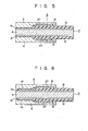
- the end section of the optical fiber cable 2 may be coupled to the optical connector 4 as shown in Fig. 6.
- Fig. 6 shows a third embodiment of the present invention.
- the same reference numerals as used in Figs. 2 and 5 denote the same parts in Fig. 6.
- a part of an exposed jacket layer 12 of an optical fiber cable is peeled off to constitute the silicone cladding 10 and the jacket layer 12 in a stepwise manner at the end section of the optical fiber cable 2.
- the silicone cladding 10 and the jacket layer 12 are inserted into deformable sleeve members 14 and 20, respectively.
- the sleeve members 14 and 20 are compressed at the outer surfaces thereof so as to bring their inner surfaces into tight contact with the silicone cladding 10 and the jacket layer 12, respectively.
- the adhesive 16 is applied to the outer surfaces of the sleeve members 14 and 20 and/or the inner surface of the through hole of the optical connector 4, and the end section of the optical fiber cable 2 is inserted into the through hole of the optical connector 4.
- the sleeve members 14 and 20 are adhered to the optical connector 4, whereby the end section of the optical fiber cable 2 is coupled to the optical connector 4.
- the jacket layer 12 and the silicone cladding 10 serve as absorbent layers, which prevent the silica glass core 8 from being damaged.
- the sleeve member 14 as the caulking member is used to prevent the optical fiber cable 2 from being bent.
- the sleeve member 20 prevents the thermal expansion and contraction stress of the jacket layer 12.
- a certain type of plug is exemplified as an optical connector.
- the method of the present invention can also be applied to another type of plug such as a bidirectional plug for coupling the end section of the optical fiber cable and the optical connector.
Landscapes
- Physics & Mathematics (AREA)
- General Physics & Mathematics (AREA)
- Optics & Photonics (AREA)
- Mechanical Coupling Of Light Guides (AREA)
Applications Claiming Priority (4)
| Application Number | Priority Date | Filing Date | Title |
|---|---|---|---|
| JP10193883A JPS59226314A (ja) | 1983-06-08 | 1983-06-08 | 光フアイバ・ケ−ブルの端末部形成方法 |
| JP101938/83 | 1983-06-08 | ||
| JP58145655A JPS6037507A (ja) | 1983-08-11 | 1983-08-11 | 光フアイバ・ケ−ブルの端末部形成方法 |
| JP145655/83 | 1983-08-11 |
Publications (2)
| Publication Number | Publication Date |
|---|---|
| EP0131742A2 true EP0131742A2 (de) | 1985-01-23 |
| EP0131742A3 EP0131742A3 (de) | 1986-01-22 |
Family
ID=26442707
Family Applications (1)
| Application Number | Title | Priority Date | Filing Date |
|---|---|---|---|
| EP84106576A Withdrawn EP0131742A3 (de) | 1983-06-08 | 1984-06-08 | Verfahren zum Aufbringen eines Steckers am Ende eines optischen Kabels |
Country Status (1)
| Country | Link |
|---|---|
| EP (1) | EP0131742A3 (de) |
Cited By (4)
| Publication number | Priority date | Publication date | Assignee | Title |
|---|---|---|---|---|
| EP0449838B1 (de) * | 1988-12-22 | 1993-12-29 | Siemens Aktiengesellschaft | Steckerstift für einen lichtwellenleiter-stecker |
| EP0735391A1 (de) * | 1995-03-31 | 1996-10-02 | SEIKOH GIKEN Co., Ltd. | Optische Faseranordnung und dessen Herstellungsverfahren |
| WO2007131471A1 (de) | 2006-05-16 | 2007-11-22 | Roland Berger | Steckverbinder mit vorrichtung zur kompensation von längenausdehnungen eines lichtwellenleiters |
| CN118210115A (zh) * | 2024-05-22 | 2024-06-18 | 四川泰瑞创通讯技术股份有限公司 | Mpo光模块、抗辐射涂层材料及抗辐射涂层 |
Family Cites Families (2)
| Publication number | Priority date | Publication date | Assignee | Title |
|---|---|---|---|---|
| US4198119A (en) * | 1978-09-13 | 1980-04-15 | International Business Machines Corporation | Connector for optical cable |
| GB2068142A (en) * | 1980-01-29 | 1981-08-05 | Plessey Co Ltd | Terminations for clad optical fibres |
-
1984
- 1984-06-08 EP EP84106576A patent/EP0131742A3/de not_active Withdrawn
Cited By (7)
| Publication number | Priority date | Publication date | Assignee | Title |
|---|---|---|---|---|
| EP0449838B1 (de) * | 1988-12-22 | 1993-12-29 | Siemens Aktiengesellschaft | Steckerstift für einen lichtwellenleiter-stecker |
| EP0735391A1 (de) * | 1995-03-31 | 1996-10-02 | SEIKOH GIKEN Co., Ltd. | Optische Faseranordnung und dessen Herstellungsverfahren |
| WO2007131471A1 (de) | 2006-05-16 | 2007-11-22 | Roland Berger | Steckverbinder mit vorrichtung zur kompensation von längenausdehnungen eines lichtwellenleiters |
| DE102006062695A1 (de) * | 2006-05-16 | 2007-11-29 | Roland Berger | Themperatur- und Luftfeuchtigkeitsänderungsausgleich bei der resultierenden Längenänderung bei LWL's um die Ein- und Austrittsposition zu halten |
| DE102006062695B4 (de) * | 2006-05-16 | 2008-05-08 | Roland Berger | Steckverbinder für einen Lichtwellenleiter |
| US7794154B2 (en) | 2006-05-16 | 2010-09-14 | Roland Berger | Plug connector for an optical fibre with device for compensation of elongations of an optical fibre |
| CN118210115A (zh) * | 2024-05-22 | 2024-06-18 | 四川泰瑞创通讯技术股份有限公司 | Mpo光模块、抗辐射涂层材料及抗辐射涂层 |
Also Published As
| Publication number | Publication date |
|---|---|
| EP0131742A3 (de) | 1986-01-22 |
Similar Documents
| Publication | Publication Date | Title |
|---|---|---|
| US4648688A (en) | Connector for fiber optic member including polishing fixture and method of terminating same | |
| US4303304A (en) | Universal optical waveguide alignment ferrule | |
| JPH10170756A (ja) | 光コネクタおよびその取付方法 | |
| US5621835A (en) | Optical fiber assembly and manufacturing method for the same | |
| US4787704A (en) | Rematable optical splice utilizing rods with resilient coating | |
| US4973129A (en) | Optical fiber element | |
| JP3530434B2 (ja) | 光学用フェルールおよび接着剤無しにファイバを設置する方法 | |
| EP0131742A2 (de) | Verfahren zum Aufbringen eines Steckers am Ende eines optischen Kabels | |
| US5085494A (en) | Fiber optic splice means and method | |
| JP2000121863A (ja) | メカニカルスプライス部、光ファイバ心線接続部及び光コネクタ付き光ファイバ心線 | |
| JPH02197807A (ja) | 光ファイバ終端結合用フェルール部材及びその製造方法 | |
| JPS60149015A (ja) | 光コネクタ | |
| EP0735391B1 (de) | Optische Faseranordnung und dessen Herstellungsverfahren | |
| JPS60185907A (ja) | 光フアイバ保護部材 | |
| JPS60186811A (ja) | 光コネクタ | |
| JPH0151807B2 (de) | ||
| JP2706908B2 (ja) | 光ファイバ組立体およびその製造方法 | |
| JPH02153308A (ja) | 光ファイバ素線 | |
| US6047097A (en) | Optical coupler | |
| JP2871914B2 (ja) | 光部品のコード化パッケージ構造 | |
| JPS6017407A (ja) | 光コネクタ | |
| JPH0894877A (ja) | 光ファイバ・コネクタ及びその組立方法 | |
| JPH0449922B2 (de) | ||
| JPS6330607B2 (de) | ||
| JPH11352333A (ja) | ファイバグレーティング付きの光コネクタフェルール |
Legal Events
| Date | Code | Title | Description |
|---|---|---|---|
| PUAI | Public reference made under article 153(3) epc to a published international application that has entered the european phase |
Free format text: ORIGINAL CODE: 0009012 |
|
| 17P | Request for examination filed |
Effective date: 19840705 |
|
| AK | Designated contracting states |
Designated state(s): DE FR GB |
|
| PUAL | Search report despatched |
Free format text: ORIGINAL CODE: 0009013 |
|
| AK | Designated contracting states |
Designated state(s): DE FR GB |
|
| 17Q | First examination report despatched |
Effective date: 19870126 |
|
| STAA | Information on the status of an ep patent application or granted ep patent |
Free format text: STATUS: THE APPLICATION IS DEEMED TO BE WITHDRAWN |
|
| 18D | Application deemed to be withdrawn |
Effective date: 19870805 |
|
| RIN1 | Information on inventor provided before grant (corrected) |
Inventor name: KATAGIRI, SHUHEIC/O PATENT DIVISION Inventor name: DONUMA, KENICHIC/O PATENT DIVISION Inventor name: HORI, AIICHIRO Inventor name: TAKAI, HIROSI |