EP0131752A2 - Lautstärkenregelung für Kabelfernsehen und dazugehöriges Verfahren - Google Patents
Lautstärkenregelung für Kabelfernsehen und dazugehöriges Verfahren Download PDFInfo
- Publication number
- EP0131752A2 EP0131752A2 EP84106672A EP84106672A EP0131752A2 EP 0131752 A2 EP0131752 A2 EP 0131752A2 EP 84106672 A EP84106672 A EP 84106672A EP 84106672 A EP84106672 A EP 84106672A EP 0131752 A2 EP0131752 A2 EP 0131752A2
- Authority
- EP
- European Patent Office
- Prior art keywords
- signal
- audio
- coupled
- demodulator
- amplitude
- Prior art date
- Legal status (The legal status is an assumption and is not a legal conclusion. Google has not performed a legal analysis and makes no representation as to the accuracy of the status listed.)
- Withdrawn
Links
- 238000000034 method Methods 0.000 title claims description 6
- 230000005236 sound signal Effects 0.000 claims abstract description 28
- 230000002238 attenuated effect Effects 0.000 claims description 2
- 230000000903 blocking effect Effects 0.000 claims 1
- 239000003990 capacitor Substances 0.000 description 15
- 230000015556 catabolic process Effects 0.000 description 7
- 238000006731 degradation reaction Methods 0.000 description 7
- 230000001276 controlling effect Effects 0.000 description 3
- 238000010586 diagram Methods 0.000 description 3
- 230000003247 decreasing effect Effects 0.000 description 2
- 230000001105 regulatory effect Effects 0.000 description 2
- 239000000919 ceramic Substances 0.000 description 1
- 230000008878 coupling Effects 0.000 description 1
- 238000010168 coupling process Methods 0.000 description 1
- 238000005859 coupling reaction Methods 0.000 description 1
- 230000010355 oscillation Effects 0.000 description 1
- 230000008569 process Effects 0.000 description 1
- 230000009467 reduction Effects 0.000 description 1
Images

Classifications
-
- H—ELECTRICITY
- H04—ELECTRIC COMMUNICATION TECHNIQUE
- H04N—PICTORIAL COMMUNICATION, e.g. TELEVISION
- H04N5/00—Details of television systems
- H04N5/44—Receiver circuitry for the reception of television signals according to analogue transmission standards
- H04N5/60—Receiver circuitry for the reception of television signals according to analogue transmission standards for the sound signals
-
- H—ELECTRICITY
- H04—ELECTRIC COMMUNICATION TECHNIQUE
- H04N—PICTORIAL COMMUNICATION, e.g. TELEVISION
- H04N7/00—Television systems
- H04N7/10—Adaptations for transmission by electrical cable
- H04N7/102—Circuits therefor, e.g. noise reducers, equalisers, amplifiers
-
- H—ELECTRICITY
- H04—ELECTRIC COMMUNICATION TECHNIQUE
- H04N—PICTORIAL COMMUNICATION, e.g. TELEVISION
- H04N7/00—Television systems
- H04N7/10—Adaptations for transmission by electrical cable
Definitions
- This invention relates, in general, to controlling audio volume in television systems, and more particularly, to a method and apparatus for controlling the volume of audio in a television pre-selector system.
- Cable television (CATV) systems typically have a tuner or control box which sets on top of a regular television receiver.
- An RF input signal containing the television signal is normally input to the CATV tuner and an output from the tuner is the connected to the antenna input jack of the television receiver.
- the output from the CATV tuner generally, only contains the signal of a preselected channel.
- Remote control systems have been devised for controlling the TV channel to which the CATV tuner is set. Some remote control systems also permit increasing or decreasing the audio volume. Such remote audio volume controllers normally require base band tuners plus video IF amplifiers/detectors and sound IF amplifiers/detectors plus remodulators. Some degradation occurs to the video portion of the signal because of the base band decoding-encoding. The degradation to the video can occur in the demodulator, with intermodulation, cross modulation, or third order harmonic products. There is also reduction of the signal to noise ratio of the signal. Some of the noise degradation can also occur during the remodulation process. Accordingly, it would be desirable to provide a separate audio volumn control which does not cause degradation of the video signal.
- Another object of the present invention is to provide an audio volume control useful in a television pre-selector system which does not degrade the video portion of the signal.
- Yet a further object of the present invention is to provide a method of processing an audio signal separately from video in a television pre-selector tuning system.
- a sound carrier demodulator which demodulates the intercarrier sound signal from the RF television signal.
- the sound carrier demodulator also provides an RF reference output.
- the demodulated intercarrier signal is further demodulated by an audio demodulator to obtain a detected audio signal.
- the audio signal is then coupled to amplitude control means which is responsive to a control signal.
- the amplitude control means can then amplify or attenuate the detected audio signal which is coupled to a modulator.
- the modulator modulates the amplitude controlled detected audio signal with the RF reference signal to provide a modulated output. This modulated output is then combined with the RF television signal which has been passed through an RF sound carrier trap to remove the sound carrier.
- CATV is intended to encompass set-top tuners including those receiving direct broadcasts from satellites or any type of pre-selector system.
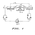
- FIG. 1 shows in block diagram form a circuit which allows remote control of the volume and mute functions in a cable television (CATV) type of tuning system.
- the circuit of FIG. 1 can perform the audio volume control functions without introducing signal to noise degradation in the video path.
- This circuit is also useful in video cassette recorder (VCR) equipment if the equipment is used in a mode where it passes the signal into the television receiver antenna input jack.
- VCR video cassette recorder
- the circuit of FIG. 1 has an RF input terminal 11 and an output terminal 12.
- Terminal 11 provides an RF television signal to RF demodulator 13 and to RF sound carrier trap 14.
- Sound carrier demodulator 13 provides an intercarrier sound signal on line 18 and an RF reference signal on line 15.
- Line 18 is connected to an input of audio demodulator/amplifier 16.
- Audio demodulator 16 provides a detected audio signal to the audio amplifier within demodulator 16.
- the amplifier receives a control input from terminal 19.
- Terminal 19 can receive a DC voltage which is used to either increase or decrease the gain of the amplifier contained in audio demodulator 16.
- the amplifier output is provided on line 21 which is connected to modulator 17.
- Modulator 17 also receives the RF reference signal from demodulator 13 by way of line 15.
- Modulator 17 remodulates the detected audio signal with the RF reference signal.
- the remodulated signal is then passed to filter network 22.
- Filter network 22 serves as an upper sideband pass network.
- the output of filter network 22 is connected to a summer 23.
- Summer 23 also receives the output from RF sound carrier trap 14.
- the output from trap 14 is video since the trap has removed the sound therefrom.
- Summer 23 recombines the video signal and the RF audio signal to provide an RF television output signal at terminal 12. This RF output signal can then be coupled to a television receiver antenna jack (not shown).
- the method of operation of the circuit of FIG. 1 is to receive the RF input at terminal 11 which is connected to demodulator 13 and RF sound carrier trap 14.
- the RF input is demodulated to obtain an intercarrier signal which is coupled to demodulator 16.
- Demodulator 13 also provides an RF reference signal on line 15.
- Demodulator 16 also contains a voltage controlled amplifier which receives a control input from terminal 19. The control signal for terminal 19 can be actuated by a remote control device.
- Demodulator/amplifier 16 provides an FM detected audio signal which is amplified, attenuated, or muted by the voltage controlled amplifier. This detected audio is then modulated by modulator 17 with the RF reference signal supplied on line 15.
- the modulated audio signal is then coupled to a summation network 23 where it is combined with the video signal supplied by trap 14, to provide an RF television signal which contains an amplitude controlled audio portion.
- FIG. 2 illustrates one manner of achieving the circuit of FIG. 1 by using standard readily available integrated circuits.
- the elements in FIG. 2 which perform functional equivalents to elements of FIG. 1 carry the same reference numerals.
- An MC13010 can be used to perform the demodulation function of demodulator 13.
- An MC1358 can be used to perform the audio demodulation plus amplitude control of the demodulated signal of demodulator/amplifier 16.
- An MC1374 can be used to provide the remodulation function of modulator 17.
- MC13010, MC1358, and MC1374 are all standard monolithic integrated circuits made and sold by Motorola, Inc. Illustration of FIG. 2 is not meant to imply that other standard integrated circuits could not be used. The use of other integrated circuits could result in dividing the functions up in a slightly different manner. Actually, in a preferred embodiment, all the active components required to perform the function illustrated in FIG. 1 will be on a single monolithic integrated circuit.
- RF input terminal 11 is connected to pin 8 of MC13010 which is illustrated as serving as demodulator 13.
- Pin 8 is connected to pin 9 by a resistor which in turn is coupled to ground by a capacitor.
- Pin 6 is connected to RF sound carrier trap 14 and to a resistor.
- the resistor is connected to a voltage terminal 26 which receives a regulated bias voltage.
- Terminal 26 is also connected to ground by a capacitor.
- Voltage VCC is applied to terminal 27 which is coupled to pin 17 by a resistor.
- Pin 17 is also coupled to ground by a capacitor.
- An RF reference signal is provided as outputs from MC13010 on pins 13 and 14 which are coupled by coupling capacitors to a tuned circuit.
- Pin 7 of MC13010 is coupled by a resistor to the regulated bias voltage terminal 26. Terminal 26 is also coupled to ground by a capacitor and pin 7 is coupled by a capacitor to pin 2. Pins 1, 3, 4, 10, 12 and 18 are coupled to ground by capacitors. Pin 5 is a ground pin and is therefore connected to ground. Pin 11 provides an output to filter 29. Filter 29 is a ceramic filter'which passes the intercarrier sound signal.
- the output of filter 29 is connected to pin 2 of MC1358 which is illustrated as serving as audio demodulator/amplifier 16.
- Pin 2 of MC1358 is coupled to pin 1 by a resistor and pin 1 is coupled to ground by a capacitor.
- Pin 5 is a power supply pin and is coupled to VCC terminal 27 by a resistor and to ground by a capacitor.
- Pins 9 and 10 of MC1358 are connected to a tank circuit which provides an FM demodulation quadrature signal.
- Pins 3 and 4 are connected to ground.
- Pin 7, 11, 12, 13, and 14 are not used in this illustrated configuration and therefore have no connections thereto.
- Pin 6 receives the DC attenuation control voltage from terminal 19.
- Pin 8 is the output for demodulator/amplifier 16 and is coupled by a capacitor to pin 14 of MC1374.
- Pins 6 and 7 of MC1374, which performs the remodulation function of modulator 17, receive the RF carrier signal through a tuned circuit.
- the tuned circuit is chosen to provide an oscillation at the RF video frequency of 61.25 MHz.
- Pins 12 and 13 of MC1374 are coupled together by a resistor.
- Pin 2 is coupled to pin 3 by a capacitor and a coil in series, and pin 3 is also coupled to ground by a capacitor and coupled to pin 1 by a capacitor and resistor in series.
- the junction formed by the series capacitor and resistor is coupled by a resistor to another resistor which is connected to pin 11 and to a capacitor which is connected to ground and to a voltage divider network which is connected between pin 27 and ground.
- Pin 8 is also connected to voltage terminal 27 and to pin 9 by a resistor.
- Pin 9 provides the modulated audio output to upper sideband pass network 22.
- Network 22 along with trap 14 provide inputs to summer 23 which is illustrated as a torroidal summer network.
- the output of summer network 23 is coupled through a T resistor network to output terminal 12.
Landscapes
- Engineering & Computer Science (AREA)
- Multimedia (AREA)
- Signal Processing (AREA)
- Television Receiver Circuits (AREA)
- Two-Way Televisions, Distribution Of Moving Picture Or The Like (AREA)
Applications Claiming Priority (2)
| Application Number | Priority Date | Filing Date | Title |
|---|---|---|---|
| US06/506,152 US4536798A (en) | 1983-06-20 | 1983-06-20 | Volume control for CATV and method therefor |
| US506152 | 1983-06-20 |
Publications (2)
| Publication Number | Publication Date |
|---|---|
| EP0131752A2 true EP0131752A2 (de) | 1985-01-23 |
| EP0131752A3 EP0131752A3 (de) | 1986-02-19 |
Family
ID=24013411
Family Applications (1)
| Application Number | Title | Priority Date | Filing Date |
|---|---|---|---|
| EP84106672A Withdrawn EP0131752A3 (de) | 1983-06-20 | 1984-06-12 | Lautstärkenregelung für Kabelfernsehen und dazugehöriges Verfahren |
Country Status (5)
| Country | Link |
|---|---|
| US (1) | US4536798A (de) |
| EP (1) | EP0131752A3 (de) |
| JP (1) | JPS6068782A (de) |
| KR (1) | KR920003722B1 (de) |
| CA (1) | CA1222560A (de) |
Cited By (1)
| Publication number | Priority date | Publication date | Assignee | Title |
|---|---|---|---|---|
| JPS61230484A (ja) * | 1985-04-04 | 1986-10-14 | Alps Electric Co Ltd | Catvコンバ−タ |
Families Citing this family (7)
| Publication number | Priority date | Publication date | Assignee | Title |
|---|---|---|---|---|
| US4652924A (en) * | 1984-12-10 | 1987-03-24 | Oak Industries Inc. | RF volume control circuit |
| US4748501A (en) * | 1984-12-11 | 1988-05-31 | Zenith Electronics Corporation | Cable converter for television signals with stereo audio signal |
| JPH089979Y2 (ja) * | 1985-09-18 | 1996-03-21 | 北菱電興株式会社 | Catvシステムの端末装置 |
| US5054071A (en) * | 1989-02-03 | 1991-10-01 | Scientific-Atlanta, Inc. | Volume control for optimum television stereo separation |
| US5428404A (en) * | 1993-01-29 | 1995-06-27 | Scientific-Atlanta, Inc. | Apparatus for method for selectively demodulating and remodulating alternate channels of a television broadcast |
| US5532733A (en) * | 1993-03-10 | 1996-07-02 | Thomson Consumer Electronics, Inc. | Remodulation of a cable box output signal to a UHF channel |
| US6909471B2 (en) * | 2002-12-03 | 2005-06-21 | Scientific-Atlanta, Inc. | Audio volume control |
Family Cites Families (5)
| Publication number | Priority date | Publication date | Assignee | Title |
|---|---|---|---|---|
| US3770120A (en) * | 1972-10-31 | 1973-11-06 | H Hanson | Merchandise display with inventory control |
| AT341595B (de) * | 1975-02-27 | 1978-02-10 | Siemens Ag Oesterreich | Einrichtung zur beeinflussung des tontragers von fernsehsignalen |
| US4237485A (en) * | 1978-01-19 | 1980-12-02 | Matsushita Electric Industrial Co., Ltd. | Buzz cancelling system for television receiver |
| US4258391A (en) * | 1979-07-31 | 1981-03-24 | Pay Television Corporation | Sound intercarrier detector |
| US4395734A (en) * | 1981-04-24 | 1983-07-26 | Zenith Radio Corporation | Remote muting for CATV/STV converters |
-
1983
- 1983-06-20 US US06/506,152 patent/US4536798A/en not_active Expired - Lifetime
-
1984
- 1984-05-01 CA CA000453219A patent/CA1222560A/en not_active Expired
- 1984-06-11 JP JP59119736A patent/JPS6068782A/ja active Pending
- 1984-06-12 EP EP84106672A patent/EP0131752A3/de not_active Withdrawn
- 1984-06-20 KR KR1019840003482A patent/KR920003722B1/ko not_active Expired
Cited By (1)
| Publication number | Priority date | Publication date | Assignee | Title |
|---|---|---|---|---|
| JPS61230484A (ja) * | 1985-04-04 | 1986-10-14 | Alps Electric Co Ltd | Catvコンバ−タ |
Also Published As
| Publication number | Publication date |
|---|---|
| KR850000873A (ko) | 1985-03-09 |
| KR920003722B1 (ko) | 1992-05-09 |
| JPS6068782A (ja) | 1985-04-19 |
| CA1222560A (en) | 1987-06-02 |
| EP0131752A3 (de) | 1986-02-19 |
| US4536798A (en) | 1985-08-20 |
Similar Documents
| Publication | Publication Date | Title |
|---|---|---|
| US4592093A (en) | Super high frequency receiver | |
| US5133009A (en) | Method and apparatus for defeating the operation of an ic built-in noise inverter | |
| US4935814A (en) | Picture quality indicator for satellite broadcasting receiver | |
| JP2814290B2 (ja) | 中間周波数信号処理装置 | |
| US4455573A (en) | Television sound receiver | |
| US4536798A (en) | Volume control for CATV and method therefor | |
| JPS5875330A (ja) | ラジオまたはテレビ受信機の受信段 | |
| KR100211412B1 (ko) | Fm 라디오를 포함하는 텔레비젼 수상기 | |
| US4591915A (en) | Remote volume control by means of frequency modulation feedback loop | |
| EP0445579B1 (de) | Quasiparallele ZF-Verarbeitung mit gemeinsamem akustischem Oberflächenwellenfilter | |
| US4511924A (en) | Frequency translation phase-locked loop for separate or intercarrier type television sound detection | |
| US4470070A (en) | Frequency translation phase-locked loop television sound detection system | |
| US4571622A (en) | Hybrid frequency modulation feedback loop remote volume control circuit | |
| US4199787A (en) | Intercarrier sound system | |
| JPS60239188A (ja) | テレビジヨン信号復調装置 | |
| US4652924A (en) | RF volume control circuit | |
| US2609441A (en) | Combination radio television receiving system | |
| JP2883782B2 (ja) | Catv用出力周波数可変形変調器 | |
| US2629769A (en) | Intercarrier television receiver | |
| JPH0450707Y2 (de) | ||
| JPS6221105Y2 (de) | ||
| KR0124970Y1 (ko) | 칼라 버스트 일정 레벨 유지 회로 | |
| KR940003931Y1 (ko) | 영상 수신회로 | |
| JPH04351081A (ja) | 多方式テレビジョン受像装置 | |
| JPH04200087A (ja) | 衛星放送受信機画質表示装置 |
Legal Events
| Date | Code | Title | Description |
|---|---|---|---|
| PUAI | Public reference made under article 153(3) epc to a published international application that has entered the european phase |
Free format text: ORIGINAL CODE: 0009012 |
|
| AK | Designated contracting states |
Designated state(s): DE GB |
|
| PUAL | Search report despatched |
Free format text: ORIGINAL CODE: 0009013 |
|
| AK | Designated contracting states |
Designated state(s): DE GB |
|
| 17P | Request for examination filed |
Effective date: 19860819 |
|
| STAA | Information on the status of an ep patent application or granted ep patent |
Free format text: STATUS: THE APPLICATION IS DEEMED TO BE WITHDRAWN |
|
| 18D | Application deemed to be withdrawn |
Effective date: 19880104 |
|
| RIN1 | Information on inventor provided before grant (corrected) |
Inventor name: REID, SYDNEY J., JR. Inventor name: ZLOTNICK, FREDRICK |