EP0131761A2 - Streufahrzeug mit aufgesetztem Winterdienst-Streugerät - Google Patents
Streufahrzeug mit aufgesetztem Winterdienst-Streugerät Download PDFInfo
- Publication number
- EP0131761A2 EP0131761A2 EP84106793A EP84106793A EP0131761A2 EP 0131761 A2 EP0131761 A2 EP 0131761A2 EP 84106793 A EP84106793 A EP 84106793A EP 84106793 A EP84106793 A EP 84106793A EP 0131761 A2 EP0131761 A2 EP 0131761A2
- Authority
- EP
- European Patent Office
- Prior art keywords
- spreading
- container
- vehicle
- vehicle according
- grit
- Prior art date
- Legal status (The legal status is an assumption and is not a legal conclusion. Google has not performed a legal analysis and makes no representation as to the accuracy of the status listed.)
- Granted
Links
Images


Classifications
-
- E—FIXED CONSTRUCTIONS
- E01—CONSTRUCTION OF ROADS, RAILWAYS, OR BRIDGES
- E01C—CONSTRUCTION OF, OR SURFACES FOR, ROADS, SPORTS GROUNDS, OR THE LIKE; MACHINES OR AUXILIARY TOOLS FOR CONSTRUCTION OR REPAIR
- E01C19/00—Machines, tools or auxiliary devices for preparing or distributing paving materials, for working the placed materials, or for forming, consolidating, or finishing the paving
- E01C19/12—Machines, tools or auxiliary devices for preparing or distributing paving materials, for working the placed materials, or for forming, consolidating, or finishing the paving for distributing granular or liquid materials
- E01C19/20—Apparatus for distributing, e.g. spreading, granular or pulverulent materials, e.g. sand, gravel, salt, dry binders
- E01C19/201—Apparatus for distributing, e.g. spreading, granular or pulverulent materials, e.g. sand, gravel, salt, dry binders with driven loosening, discharging or spreading parts, e.g. power-driven, drive derived from road-wheels
- E01C19/202—Apparatus for distributing, e.g. spreading, granular or pulverulent materials, e.g. sand, gravel, salt, dry binders with driven loosening, discharging or spreading parts, e.g. power-driven, drive derived from road-wheels solely rotating, e.g. discharging and spreading drums
- E01C19/203—Centrifugal spreaders with substantially vertical axis
-
- E—FIXED CONSTRUCTIONS
- E01—CONSTRUCTION OF ROADS, RAILWAYS, OR BRIDGES
- E01C—CONSTRUCTION OF, OR SURFACES FOR, ROADS, SPORTS GROUNDS, OR THE LIKE; MACHINES OR AUXILIARY TOOLS FOR CONSTRUCTION OR REPAIR
- E01C19/00—Machines, tools or auxiliary devices for preparing or distributing paving materials, for working the placed materials, or for forming, consolidating, or finishing the paving
- E01C19/12—Machines, tools or auxiliary devices for preparing or distributing paving materials, for working the placed materials, or for forming, consolidating, or finishing the paving for distributing granular or liquid materials
- E01C19/20—Apparatus for distributing, e.g. spreading, granular or pulverulent materials, e.g. sand, gravel, salt, dry binders
- E01C19/205—Apparatus for distributing, e.g. spreading, granular or pulverulent materials, e.g. sand, gravel, salt, dry binders the material being spread by means of a gaseous current
-
- E—FIXED CONSTRUCTIONS
- E01—CONSTRUCTION OF ROADS, RAILWAYS, OR BRIDGES
- E01H—STREET CLEANING; CLEANING OF PERMANENT WAYS; CLEANING BEACHES; DISPERSING OR PREVENTING FOG IN GENERAL CLEANING STREET OR RAILWAY FURNITURE OR TUNNEL WALLS
- E01H10/00—Improving gripping of ice-bound or other slippery traffic surfaces, e.g. using gritting or thawing materials ; Roadside storage of gritting or solid thawing materials; Permanently installed devices for applying gritting or thawing materials; Mobile apparatus specially adapted for treating wintry roads by applying liquid, semi-liquid or granular materials
- E01H10/007—Mobile apparatus specially adapted for preparing or applying liquid or semi-liquid thawing material or spreading granular material on wintry roads
-
- E—FIXED CONSTRUCTIONS
- E01—CONSTRUCTION OF ROADS, RAILWAYS, OR BRIDGES
- E01C—CONSTRUCTION OF, OR SURFACES FOR, ROADS, SPORTS GROUNDS, OR THE LIKE; MACHINES OR AUXILIARY TOOLS FOR CONSTRUCTION OR REPAIR
- E01C19/00—Machines, tools or auxiliary devices for preparing or distributing paving materials, for working the placed materials, or for forming, consolidating, or finishing the paving
- E01C19/12—Machines, tools or auxiliary devices for preparing or distributing paving materials, for working the placed materials, or for forming, consolidating, or finishing the paving for distributing granular or liquid materials
- E01C19/20—Apparatus for distributing, e.g. spreading, granular or pulverulent materials, e.g. sand, gravel, salt, dry binders
- E01C2019/2055—Details not otherwise provided for
- E01C2019/207—Feeding the distribution means
- E01C2019/208—Feeding the distribution means with longitudinal auger
Definitions
- the invention relates to a spreading vehicle with attached winter service spreading device for solid and / or liquid spreading materials, which has at least one spreading material container and a spreading device arranged behind the spreading material container in the direction of travel with a spreading plate rotating about an essentially vertical axis, from which the spreading material is spread out in a fan-like manner .
- Winter service spreading devices of a more recent design are generally set up in such a way that they are capable of spreading so-called truncated spreading material, namely sand or grit, as well as thawing materials, in particular salts, in a dry or moistened state.
- De-icing salt is often moistened with a metered liquid before or during the spreading process, so that it adheres better to traffic areas and is much less exposed to the danger both during and after spreading due to the natural wind or the wind from the spreading vehicle or other vehicles. to be blown away.
- the invention has for its object to provide winter service spreading vehicles of the type mentioned with a device through which the suction and the turbulence causing the swirling and drifting effects and the air turbulence are eliminated or rendered harmless and thus a more targeted, economical and environmental damage reducing spreading of the grit is made possible.
- a contour of the spreading vehicle and / or the spreading material container is arranged laterally and / or upwardly projecting wind deflector surface, which directs the detected wind down to the spreading material fan generated by the spreading disc.
- This device not only has the advantage that it can be implemented easily and at relatively low cost, or can also be retrofitted to spreading vehicles or winter service spreading devices that are already in use, but it has the advantageous property that its intended effect is automatic adapts to the given driving speed of the winter service spreading vehicle and that even at low driving speeds the spreading material leaving the spreading plate in a fan shape during its flight is pressed directly onto the traffic area to be sprinkled by the air flow directed downwards and that harmful air vortices are almost completely suppressed will.
- This downward-directed air flow generated by the airstream baffle also has the additional advantage that the crust formation on the spreader parts and vehicle parts that has occurred in the previous salt, but especially damp salt scattering is almost completely, but at least largely prevented.
- the device according to the invention additionally contributes to improving operational safety, because such crusting of road salt on vehicle or. on spreader parts often lead to malfunctions or material damage.
- theußwindleit Structure from a flat or curved wall, z. B. consist of a sheet of metal or a plastic sheet.
- the airflow guiding surface is part of a hood-like wind tunnel which on both sides runs at least approximately parallel to the longitudinal axis of the vehicle and / or the grit container and connects these wall elements , the upper outline of the grit container spans the roof wall at a vertical distance.
- Such a shaping can produce an increased or more concentrated downward air pressure, which affects the spreading material.
- the airflow guide surface is attached directly to the rear end of the grit container by means of spacers.
- the spacers are articulated to the airflow guide surface and / or the grit container and the inclination of the airflow guide surface is adjustable.
- the spacers which are articulated to the airflow control surface and / or to the grit container not only the most favorable inclination of the airflow control surface with respect to a given driving speed or with respect to the grit to be spread can be set but it is also possible to bring the headwind surface in its most favorable position in relation to the spreading disc position.
- the airflow guide surface can be brought from its position of use into an at least approximately wind-neutral position and can be fixed in it. This configuration should make it possible to bring the airflow control surface for overland journeys to the place of use or from the place of use to the home location in a position in which it generates the lowest possible air resistance without having to be completely dismantled.
- a truck 1 is shown in side view, on the loading platform 2, a winter service spreader 3 is placed.
- the winter service spreader 5 has a grit container 4, which consists of a sheet metal body with oblique walls 6 leading to a conveyor trough 5 and an upper rectangular frame 7 and has three horizontal transverse foot rails 8 and lateral supports 9.
- a longitudinal screw conveyor not visible in the drawing, which is driven by a hydraulic motor 10 in proportion to the driving speed and conveys the spreading material through a horizontal conveying pipe 11 into a down pipe 12 of a spreading device 13, through which it passes over a chute 14 onto one vertical axis 15 rotating spreader plate 16, which spreads it like a fan on the traffic surface 17 to be sprinkled.
- the spreader 13 as seen in the direction of arrow 18, is located behind the grit container 4 outside the loading platform 2 and that the spreading plate 16 is arranged with a relatively small vertical distance above the traffic area 17 to be sprinkled.
- FIG. 3 Due to the articulated connection of the spacers 26, 27 and 2S, it is possible to convert the airflow control surface 20 into one indicated by dashed lines in FIG. 1 when the winter service spreading device 3 is not in operation
- This embodiment of FIG. 3 has the advantage that the upper outlines of the grit container 4 are not surmounted by the airflow guide surface 20/1 and that the airflow guide surface in no way hinders the opening and closing of the grit container cover.
- the airflow guide surface 20/2 is formed by an obliquely curved sheet metal plate 22/1, which is provided with lateral bevels 24/2 and 25/2 and is adjustable by means of spacers 26/1 and with support brackets 27/1 is attached to the rectangular frame 7 of the grit container 4.
- the sheet 22/1 has a greater width than the grit container 4, and its arrangement is such that it also extends beyond the upper contour lines of the grit container 4 in order to direct the detected wind during the spreading operation onto the grit boxes generated by the grit plate 16.
- the airflow guide surface 20/3 arranged above the spreading device 15 forms a hood-like wind tunnel 22 together with two lateral vertical wall elements 24/5 and 25/3 and with a roof wall 21/3 / 3, which protrudes the outlines of the grit container 4 both upwards and on both sides.
- a flat, downwardly directed airflow guide surface 20/1 with a flat roof wall 21/1 and side wall elements 24/1 and 25/1 forms a windscreen hood which only projects beyond the outlines of the grit container 4, that is to say wider is defined as the scattering g ut thinkinger 4 and therefore detects only the lateral wind and directs the grit downwards compartments. It is expedient if additional baffles are arranged inside the windscreen hood, which partially deflect the lateral airstream towards the center in order to achieve the most uniform possible air flow across the spreading material fan over the entire width.
- the roof wall 21/1 is provided with a rectangular recess 21/2 which is adapted to the rear circumferential line of the grit container 4, so that a certain overlap between the side wall elements 24/1 and 25/1 on the one hand and the rectangular frame 7 of the grit container 4 on the other hand is brought about can and the entire windscreen hood can be attached to the rectangular frame 7 by means of lateral bolts 30 and 31.
- angled support rails 32 and 33 are provided for fastening the windscreen hood.
- this windscreen hood 22/3 which forms the headwind guide surface 20/3 and is directed obliquely downward, is arched from a straight upper boundary edge 22/4, which at the same time represents the connecting edge with the roof wall 21/3.
- the front boundary edge 21/4 of the roof wall 21/3 also has an upwardly protruding curvature.
- This windscreen hood 22/3 is fastened by means of spacers 26/3 and 27/3 which are arranged in pairs and are articulated and which are articulated on the side wall elements 24/3 and 25/3 or on the side supports 9.
- this windscreen hood 22/3 can also be adjusted with respect to the direction of its airflow guide surface 22/3 or, as indicated in FIG. 1, can be brought into a position in which it opposes the airflow as little as possible.
- the airflow guide surface 20/4 has a shell-like hollow shape with an approximately semi-elliptical lower boundary edge 33, which limits a substantially narrower cross section than its upper boundary edges 34, 35 and 36, which are connected to side wall elements 24/4 and 25/4 or, on gable roof-like roof wall sections 38 and approximately running parallel to the cover surfaces of the grit container 4 39 connect.
- the draft shield 40 thus formed projects beyond the outlines of the grit container 4 both upwards and laterally.
- Two articulated spacers 26/3 are provided for attaching the headwind hood 40 to the grit container 4.
- a support bracket 41 is articulated on the conveyor tube 11 by means of an articulated bracket 11 ', which can be adjustably connected to a support tongue 43 by means of a plug mandrel 42.
- the support tongue 43 is fastened in the center near the lower boundary edge 33 to the wall of the air draft hood 40 forming the airflow guide surface 20/4 and provided with a plug-in hole for receiving the plug-in mandrel 42, while the support tab 41 has a plurality of plug-in holes 44 at its upper end .
Landscapes
- Engineering & Computer Science (AREA)
- Architecture (AREA)
- Civil Engineering (AREA)
- Structural Engineering (AREA)
- Special Spraying Apparatus (AREA)
- Remote Monitoring And Control Of Power-Distribution Networks (AREA)
- Body Structure For Vehicles (AREA)
- Cleaning Of Streets, Tracks, Or Beaches (AREA)
- Vehicle Waterproofing, Decoration, And Sanitation Devices (AREA)
Abstract
Description
- Streufahrzeug mit aufgesetztem Winterdienst-Streugerät
- Die Erfindung betrifft ein Streufahrzeug mit aufgesetztem Winterdienst-Streugerät für feste und/oder flüssige Streustoffe, welches wenigstens einen Streugutbehälter und eine in Fahrtrichtung hinter dem Streugutbehälter angeordnete Streuvorrichtung mit einem um eine im wesentlichen vertikale Achse rotierenden Streuteller aufweist, von dem das Streugut fächerartig ausgestreut wird. Winterdienst-Streugeräte neuerer Bauart sind in der Regel so eingerichtet, daß sie in der Lage sind sowohl sogenanntes abstumpfendes Streugut, nämlich Sand oder Splitt als auch Taustoffe, insbesondere Salze in trockenem oder angefeuchtetem Zustand auszustreuen. Dabei wird Streusalz häufig vor oder während des Ausstreuvorganges mit einer dosiert beigegebenen Flüssigkeit angefeuchtet, damit es auf den Verkehrsflächen besser haftet und sowohl während als auch nach dem Ausstreuen durch den natürlichen Wind oder den Fahrtwind des Streufahrzeuges oder anderer Fahrzeuge wesentlich weniger der Gefahr ausgesetzt ist, verweht zu werden.
- Die Erfahrung zeigt, daß insbesondere bei schnellfahrenden Streufahrzeugen, z. B. auf Autobahnen und Schnellstraßen, infolge des an der Rückseite entstehenden Soges bzw. der dort auftretenden Luftturbulenzen auch bei angefeuchtetem Streugut noch sehr große Verwirbelungs- und Verwehungseffekte auftreten, die ein gezieltes Ausstreuen des Streugutes auf die Verkehrsflächen stark beeinträchtigen, und zu großen Streugutverlusten führen können. Dadurch wird nicht nur ein erheblicher Teil des Streugutes zwecklos vergeudet sondern es wird dadurch auch Streugut auf Kulturen abgelagert, die an die zu bestreuenden Verkehrsflächen angrenzen, wo das Streugut, insbesondere wenn es sich um Taustoffe handelt, erhebliche Schäden verursachen kann.
- Der Erfindung liegt die Aufgabe zugrunde Winterdienst-Streufahrzeuge der genannten Art mit einer Vorrichtung zu versehen, durch welche auf einfache Weise der die Verwirbelungs- und Verwehungseffekte verursachende Sog und die Luftturbulenzen beseitigt bzw. unschädlich gemacht werden und somit ein gezielteres, sparsameres und Umweltschäden verminderndes Ausstreuen des Streugutes ermöglicht wird.
- Gelöst wird diese Aufgabe erfindungsgemäß dadurch, daß oberhalb der Streuvorrichtung eine die Umrißlinien des Streufahrzeuges und/oder des Streugutbehälters seitlich und/oder nach oben überragende Fahrtwindleitfläche angeordnet ist, die den erfaßten Fahrtwind nach unten auf den vom Streuteller erzeugten Streugutfächer leitet.
- Diese Vorrichtung hat nicht nur den Vorzug, sich einfach und mit verhältnismäßig geringem Kostenaufwand realisieren zu lassen bzw. auch nachträglich an bereits am Einsatzort befindliche Streufahrzeuge bzw. Winterdienst-Streugeräte montieren zu lassen, sondern sie besitzt die vorteilhafte Eigenschaft, daß sich ihr beabsichtigter Effekt selbsttätig an die jeweils gegebene Fahrgeschwindigkeit des Winterdienst-Streufahrzeuges anpaßt und daß auch schon bei geringer Fahrgeschwindigkeit das den Streuteller fächerförmig verlassende Streugut während seines Fluges, durch die von oben nach unten gerichtete Luftströmung unmittelbar auf die zu bestreuende Verkehrsfläche gedrückt wird und daß schädliche Luftwirbel nahezu vollständig unterdrückt werden. Durch diese nach unten gerichtete von der Fahrtwindleitfläche erzeugte Luftströmung wird zusätzlich noch der Vorteil erzielt, daß die bei der bisherigen Salz-, insbesondere aber Feuchtsalzstreuung auftretende Krustenbildung an Streugeräteteilen und Fahrzeugteilen nahezu vollständig zumindest aber weitgehend verhindert wird.
- Somit trägt die erfindungsgemäße Vorrichtung zusätzlich noch zur Verbesserung der Betriebssicherheit bei, denn solche Verkrustungen von Streusalz an Fahrzeug-bzw. an Streugeräteteilen führen oft zu Betriebsstörungen bzw. zu Materialbeschädigungen.
- In ihrer einfachsten Ausführungsform, kann die Fahrtwindleitfläche aus einer ebenen oder nach hinten gewölbten Wand, z. B. aus einer Blechtafel oder aus einer Kunststofftafel bestehen.
- Um jedoch eine größere, für höhere Fahrgeschwindigkeiten besser geeignete Stabilität und Wirkungsweise zu erzielen, ist es zweckmäßiger, wenn die Fahrtwindleitfläche Teil eines haubenartigen Windtunnels ist, der beidseitig zumindest annähernd parallel zur Längsachse des Fahrzeuges und/oder des Streugutbehälters verlaufende Wandelemente und eine diese Wandelemente verbindende, die obere Umrißlinie des Streugutbehälters in vertikalem Abstand überspannende Dachwand aufweist.
- Insbesondere für Streugut mit hohem spezifischem Gewicht und/oder mit guten Hafteigenschaften, wie z. B. für Feuchtsalz, kann es bei bestimmten Fahrgeschwindigkeiten, von Vorteil sein, wenn die Fahrtwindleitfläche eine muschelartig gewölbte, sich nach unten verengende Form mit einem etwa halbkreis- oder halbellipsenförmigen unteren Begrenzungsrand aufweist.
- Durch eine solche Formgebung kann ein erhöhter bzw. konzentrierterer nach unten gerichteter Luftdruck erzeugt werden, der sich auf das Streugut auswirkt.
- Am zweckmäßigsten ist es, wenn die Fahrtwindleitfläche mittels Abstandhaltern unmittelbar am hinteren Ende des Streugutbehälters befestigt ist.
- Es ist auch denkbar, die Fahrtwindleitfläche durch geeignete Verbindungselemente unmittelbar am Fahrzeug zu befestigen. Da die Fahrtwindleitfläche jedoch nur in Verbindung mit dem Winterdienst-Streugerät, zudem auch der Streugutbehälter gehört, verwendet wird, ist es sinnvoller, die Fahrtwindleitfläche unmittelbar am Streugutbehälter zu befestigen, so daß sie zu dem im bezug auf den Streuteller eine feste Lage einnimmt.
- Zweckmäßig ist es darüber hinaus, wenn die Abstandhalter gelenkig an der Fahrtwindleitfläche und/oder am Streugutbehälter befestigt sind und die Neigung der Fahrtwindleitfläche einstellbar ist. Mit Hilfe der gelenkig an der Fahrtwindleitfläche und/oder am Streugutbehälter befestigten Abstandhalter läßt sich nicht nur die jeweils bezüglich einer vorgegebenen Fahrgeschwindigkeit oder bezüglich des jeweils auszubringenden Streugutes günstigste Neigung der Fahrtwindleitfläche einstellen sondern es ist auch möglich, die Fahrtwindleitfläche in ihrer Höhe im bezug auf die Streutellerlage in ihre jeweils günstigste Position zu bringen. In weiterer Ausgestaltung der Erfindung ist vorgesehen, daß die Fahrtwindleitfläche aus ihrer Gebrauchslage in eine zumindest annähernd fahrtwindneutrale Stellung bringbar und in dieser fixierbar ist. Durch diese Ausgestaltung soll es möglich sein, die Fahrtwindleitfläche für Uberlandfahrten zum Einsatzort oder vom Einsatzort zum Heimatstandort in eine Lage zu bringen, in der sie den geringstmöglichen Luftwiderstand erzeugt, ohne vollständig demontiert werden zu müssen.
- Anhand der Zeichnung werden mehrere Ausführungsbeispiele der Erfindung im folgenden näher erläutert. Es zeigt:
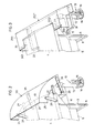
- Fig. 1 ein Winterdienst-Streufahrzeug mit aufgesetztem Winterdienst-Streugerät in Seitenansicht
- Fig. 2 den hinteren Abschnitt des Winterdienst-Streugerätes der Fig. 1 mit einem aufgesetzten Fahrtwindtunnel
- Fig. 3 den hinteren Abschnitt des Winterdienst-Streugerätes der Fig. 1 in perspektivischer Darstellung mit einem anderen Fahrtwindtunnel
- Fig. 4 das Winterdienst-Streugerät der Fig. 1 in perspektivischer Darstellung mit einer aus einer gewölbten Wand bestehenden Fahrtwindleitfläche
- Fig. 5 das Winterdienst-Streugerät der Fig. 1 mit einer weiteren Ausführungsform eines Fahrtwindtunnels
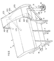
- Fig. 6 das Winterdienst-Streugerät der Fig. 1 mit einer weiteren Ausführungsform eines muschelartigen Fahrtwindtunnels.
- In Fig. 1 ist in Seitenansicht ein Lastkraftfahrzeug 1 dargestellt, auf dessen Ladepritsche 2 ein Winterdienst-Streugerät 3 aufgesetzt ist. Das Winterdienst-Streugerät 5 weist einen Streugutbehälter 4 auf, der aus einem Blechkörper mit schrägen, zu einer Fördermulde 5 führenden Wänden 6 und einem oberen Rechteckrahmen 7 besteht und drei horizontale quer verlaufende Fußholme 8 sowie seitliche Stützen 9 besitzt. Im Förderschacht 5 befindet sich eine in der Zeichnung nicht sichtbare längsverlaufende Förderschnecke, die von einem Hydraulikmotor 10 fahrgeschwindigkeitsproportional angetrieben wird und das Streugut durch ein horizontales Förderrohr 11 in ein Fallrohr 12 einer Streuvorrichtung 13 befördert, durch welches es über eine Rutsche 14 auf einen um eine vertikale Achse 15 rotierenden Streuteller 16 gelangt, der es fächerartig auf die zu bestreuende Verkehrsfläche 17 ausstreut. Es ist aus der Fig. 1 ohne weiteres erkennbar, daß sich die Streuvorrichtung 13 in Fahrtrichtung des Pfeiles 18 gesehen hinter dem Streugutbehälter 4 ausserhalb der Ladepritsche 2 befindet und daß der Streuteller 16 mit einem verhältnismäßig geringen vertikalen Abstand über der zu bestreuenden Verkehrsfläche 17 angeordnet ist. Oberhalb der Streuvorrichtung 13 ist in einem gewissen Abstand von der oberen hinteren Begrenzungskante 19 des Streugutbehälters 4 eine Fahrtwindleitfläche 20 im Form einer Blechtafel 21 angeordnet, die einen unteren geraden Abschnitt 22 und einen oberen nach vorne gebogenen Abschnitt 23 aufweist und mit seitlichen zueinander und zur Fahrzeuglängsachse parallelen Wandelementen 24 und 25 versehen ist und mit diesen eine Art Windtunnel bildet. Mit Hilfe mehrerer laschenartiger Abstandhalter 26, 27 und 28, die jeweils paarweise gelenkig an den seitlichen Wandelementen 24 und 25 sowie am Rechteckrahmen 7 bzw. an besonderen Stützelementen 29 des Streugutbehälters befestigt sind und die Fahrtwindleitfläche 20 in der gewünschten Lage halten, in welcher sie während des Streubetriebes den auftretenden Fahrtwind, soweit sie die Umrisse des Streugutbehälters 4 überragt, erfaßt und auf den vom Streuteller 16 erzeugten Streugutfächer lenkt, wie das durch kleine Pfeile in Fig. 1 angedeutet ist.
- Durch die gelenkige Verbindung der Abstandhalter 26, 27 und 2S ist es möglich, die Fahrtwindleitfläche 20, wenn das Winterdienst-Streugerät 3 nicht in Betrieb ist, in eine in Fig. 1 in gestrichelten Linien angedeutete Diese Ausführungsform der Fig. 3 hat den Vorteil, daß die oberen Umrisse des Streugutbehälters 4 von der Fahrtwindleitfläche 20/1 nicht überragt werden und daß die Fahrtwindleitfläche das Öffnen und Schließen der Streugutbehülterabdeckung in keiner Weise behindert.
- Beim Ausführungsbeispiel der Fig. 4 wird die Fahrtwindleitfläche 20/2 von einer schräg gestellten nach hinten gewölbten Blechtafel 22/1gebildet, die mit seitlichen Abkantungen 24/2 und 25/2 versehen ist und mittels Abstandhaltern 26/1 sowie mit Stützlaschen 27/1 verstellbar am Rechteckrahmen 7 des Streugutbehälters 4 befestigt ist. Dabei weist die Blechtafel 22/1eine größere Breite als der Streugutbehälter 4 auf, und ihre Anordnung ist so getroffen, daß sie die oberen Umrisslinien des Streugutbehälters 4 ebenfalls überragt,um den erfaßten Fahrtwind während des Streubetriebes auf den vom Streuteller 16 erzeugten Streugutfächer zu lenken.
- Bei der in Fig. 5 dargestellten Ausführungsform bildet die, wie bei allen anderen Ausführungsbeispielen, oberhalb der Streuvorrichtung 15 angeordnete Fahrtwindleitfläche 20/3 gemeinsam mit zwei seitlichen vertikalen Wandelementen 24/5 und 25/3 sowie mit einer Dachwand 21/3 einen haubenartigen Windtunnel 22/3, der die Umrisse des Streugutbehälters 4 sowohl nach oben als auch beidseitig überragt.
- Stellung zu bringen und in dieser zu fixieren, in welcher diese Fahrtwindleitfunktion weitgehend aufgehoben und der Luftwiderstand während des Fahrens möglichst gering ist.
- Bei der Ausführungsform der Fig. 3 bildet eine ebene schräg nach unten gerichtete Fahrtwindleitfläche 20/1 mit einer ebenen Dachwand 21/1 und seitlichen Wandelementen 24/1 und 25/1 eine Windfanghaube, die nur seitlich die Umrisse des Streugutbehälters 4 überragt, also breiter ist als der Streugutbehälter 4 und die deshalb nur den seitlichen Fahrtwind erfaßt und nach unten auf den Streugutfächer leitet. Dabei ist es zweckmäßig, wenn innerhalb der Windfanghaube zusätzlich Leitbleche angeordnet sind, welche den seitlichen Fahrtwind teilweise zur Mitte hin ablenken um über die gesamte Breite eine möglichst gleichmäßige Luftströmung auf den Streugutfächer zu erzielen. Die Dachwand 21/1 ist mit einer rechteckigen, der rückwärtigen Umfangslinie des Streugutbehälters 4 angepaßten Ausnehmung 21/2 versehen, damit eine gewisse Überschneidung zwischen den seitlichen Wandelementen 24/1 und 25/1 einerseits und dem Rechteckrahmen 7 des Streugutbehälters 4 andererseits zustande gebracht werden kann und die gesamte Windfanghaube mittels seitlichen Bolzen 30 und 31 am Rechteckrahmen 7 befestigt werden kann. Zusätzlich sind zur Befestigung der Windfanghaube abgewinkelte Stützschienen 32 und 33 vorgesehen.
- Dabei ist die die Fahrtwindleitfläche 20/3 bildende, schräg nach unten gerichtete Rückwand dieser Windfanghaube 22/3 von einer Geraden oberen Begrenzungskante 22/4, die zugleich die Verbindungskante mit der Dachwand 21/3 darstellt, nach unten hin rückwärts ausladend gewölbt. Ebenso weist auch die vordere Begrenzungskante 21/4 der Dachwand 21/3 eine nach oben ausladende Wölbung auf. Befestigt ist diese Windfanghaube 22/3 mittels jeweils paarweise angeordneter und gelenkig befestigter Abstandhalter 26/3 und 27/3, die an den seitlichen Wandelementen 24/3 und 25/3 bzw. an den seitlichen Stützen 9 angelenkt sind. Durch zusätzliche nicht dargestellte Mittel, ist auch diese Windfanghaube 22/3 bezüglich der Leitrichtung ihrer Fahrtwindleitfläche 22/3 verstellbar bzw. wie in Fig. 1 angedeutet, in eine Position bringbar, in welcher sie dem Fahrtwind einen möglichst geringen Widerstand entgegensetzt.
- Bei der in Fig. 6 dargestellten Ausführungsform besitzt die Fahrtwindleitfläche 20/4 eine muschelartige Hohlform mit einer etwa halbellipsenförmigen unteren Begrenzungskante 33, die einen wesentlich engeren Querschnitt begrenzt, als ihre oberen Begrenzungskanten 34, 35 und 36, die an seitliche Wandelemente 24/4 bzw. 25/4 bzw, an satteldachartige, etwa parallel zu den Deckelflächen des Streugutbehälters 4 verlaufende Dachwandabschnitte 38 und 39 anschließen. Die so gebildete Fahrtwindfanghaube 40 überragt die Umrisse des Streugutbehälters 4 sowohl nach oben als auch seitlich. Weil der von der unteren halbellipsenförmigen Begrenzungskante 33 umschlossene Hohlraum jedoch querschnittsmäßig wesentlich kleiner ist als die frontseitige Windfangfläche,entsteht eine Luftkomprimierung und somit eine Erhöhung der Strömungsgeschwindigkeit bzw. eine Verbesserung des beabsichtigten Zweckes, der darin besteht, das sich im Flug befindliche Streugut nach unten auf die zu bestreuende Verkehrsfläche zu drücken. Zur Befestigung der Fahrtwindfanghaube 40 am Streugutbehälter 4 sind zwei gelenkig angeordnete Abstandhalter 26/3 wie beim Ausführungsbeispiel der Fig. 5 vorgesehen. Zudem ist auf dem Förderrohr 11 mittels eines Gelenkbockes 11' eine Stützlasche 41 angelenkt, die mittels eines Steckdornes 42 verstellbar mit einer Stützzunge 43 verbindbar ist. Die Stützzunge 43 ist mittig in der Nähe der unteren Begrenzungskante 33 an der die Fahrtwindleitfläche 20/4 bildenden Wand der Fahrtwindfanghaube 40 befestigt und mit einer Steckbohrung zur Aufnahme des Steckdornes 42 versehen, während die Stützlasche 41 an ihrem oberen Ende eine Vielzahl von Steckbohrungen 44 aufweist.
- Bei allen Ausführungsformen ist es ohne weiteres möglich die Fahrtwindfangfläche auch nachträglich an einem Streugerät oder an einem Streufahrzeug zu montieren, wobei jeweils Befestigungsmittel verwendet werden können, die eine sowohl während des Streuhetriebes als auch ausserhalb des Streubetriebes zweckmäßige Anordnung und Einstellung der Fahrtwindleitfläche ermöglichen.
Claims (8)
Applications Claiming Priority (2)
| Application Number | Priority Date | Filing Date | Title |
|---|---|---|---|
| DE3325940 | 1983-07-19 | ||
| DE3325940A DE3325940C1 (de) | 1983-07-19 | 1983-07-19 | Streufahrzeug mit aufgesetztem Winterdienst-Streugeraet |
Publications (3)
| Publication Number | Publication Date |
|---|---|
| EP0131761A2 true EP0131761A2 (de) | 1985-01-23 |
| EP0131761A3 EP0131761A3 (en) | 1986-03-26 |
| EP0131761B1 EP0131761B1 (de) | 1988-01-13 |
Family
ID=6204316
Family Applications (1)
| Application Number | Title | Priority Date | Filing Date |
|---|---|---|---|
| EP84106793A Expired EP0131761B1 (de) | 1983-07-19 | 1984-06-14 | Streufahrzeug mit aufgesetztem Winterdienst-Streugerät |
Country Status (7)
| Country | Link |
|---|---|
| EP (1) | EP0131761B1 (de) |
| AT (1) | AT384847B (de) |
| CH (1) | CH662143A5 (de) |
| DE (1) | DE3325940C1 (de) |
| DK (1) | DK153338C (de) |
| FI (1) | FI74091C (de) |
| NO (1) | NO157944C (de) |
Families Citing this family (8)
| Publication number | Priority date | Publication date | Assignee | Title |
|---|---|---|---|---|
| DE3808934A1 (de) * | 1988-03-17 | 1989-10-05 | Kuepper Weisser Gmbh | Aufsetzvorrichtung fuer ein streugeraet |
| DE3829716A1 (de) * | 1988-09-01 | 1990-04-05 | Schoerling Waggonbau | Streufahrzeug mit einer streuanlage |
| DE4038268C1 (en) * | 1990-11-30 | 1992-05-07 | Kuepper-Weisser Gmbh, 7715 Braeunlingen, De | Road grit spreading vehicle with endless conveyor - has hydraulic system, whose medium is cooled by line with metal cooling section |
| DE9108410U1 (de) * | 1991-07-08 | 1991-09-19 | Küpper-Weisser GmbH, 7715 Bräunlingen | Winterdienst-Streugerät mit Fahrtwindleitfläche |
| IT1288747B1 (it) * | 1996-10-11 | 1998-09-24 | Giletta Michele S P A | Veicolo per lo spargimento di prodotti sul manto stradale, in particolare prodotti antigelo |
| DE29618218U1 (de) * | 1996-10-21 | 1996-12-12 | Küpper-Weisser GmbH, 78199 Bräunlingen | Winterdienst-Streugerät mit einer Förderschnecke oder einer Förderwendel und Rührwelle |
| DE19838979C1 (de) | 1998-08-27 | 1999-12-30 | Schmidt Holding Europ Gmbh | Streugerät |
| ATE457388T1 (de) * | 2006-08-01 | 2010-02-15 | Kuepper Weisser Gmbh | Winterdienst-streufahrzeug |
Family Cites Families (2)
| Publication number | Priority date | Publication date | Assignee | Title |
|---|---|---|---|---|
| AT249732B (de) * | 1964-07-13 | 1966-10-10 | Max Engler | Streuvorrichtung |
| DE2632794C2 (de) * | 1976-07-21 | 1978-08-24 | Hubert Weisser Kg, 7715 Braeunlingen | Salzstreugerät mit Streugutbefeuchtungseinrichtung für ein Fahrzeug |
-
1983
- 1983-07-19 DE DE3325940A patent/DE3325940C1/de not_active Expired
- 1983-09-15 AT AT0329283A patent/AT384847B/de not_active IP Right Cessation
- 1983-09-15 CH CH5027/83A patent/CH662143A5/de not_active IP Right Cessation
-
1984
- 1984-06-12 NO NO842336A patent/NO157944C/no not_active IP Right Cessation
- 1984-06-14 EP EP84106793A patent/EP0131761B1/de not_active Expired
- 1984-07-12 FI FI842810A patent/FI74091C/fi not_active IP Right Cessation
- 1984-07-18 DK DK350684A patent/DK153338C/da not_active IP Right Cessation
Also Published As
| Publication number | Publication date |
|---|---|
| NO157944C (no) | 1988-06-15 |
| NO842336L (no) | 1985-01-21 |
| DK350684A (da) | 1985-01-20 |
| DK153338B (da) | 1988-07-04 |
| DK350684D0 (da) | 1984-07-18 |
| EP0131761A3 (en) | 1986-03-26 |
| FI74091C (fi) | 1987-12-10 |
| FI74091B (fi) | 1987-08-31 |
| FI842810A0 (fi) | 1984-07-12 |
| DE3325940C1 (de) | 1985-03-14 |
| FI842810A7 (fi) | 1985-01-20 |
| AT384847B (de) | 1988-01-11 |
| NO157944B (no) | 1988-03-07 |
| EP0131761B1 (de) | 1988-01-13 |
| CH662143A5 (de) | 1987-09-15 |
| DK153338C (da) | 1988-11-14 |
| ATA329283A (de) | 1987-06-15 |
Similar Documents
| Publication | Publication Date | Title |
|---|---|---|
| EP0079399B1 (de) | Reinigungsvorrichtung zum Reinigen des Luftfilters eines Kühlluftgehäuses mit einem ein Gebläse aufweisenden Kühler | |
| EP2835471B2 (de) | Selbstfahrende Straßenfräsmaschine, sowie Verfahren zum Abfräsen und Abtransportieren eines abgefrästen Materialstroms | |
| EP0131761B1 (de) | Streufahrzeug mit aufgesetztem Winterdienst-Streugerät | |
| EP0574740A1 (de) | Vorrichtung zum Ausbringen von Behandlungsflüssigkeit auf Pflanzenreihen | |
| CH631773A5 (de) | Schneeschleuder, insbesondere fuer den anbau an eisenbahnfahrzeuge. | |
| DE602004002816T2 (de) | Verfahren zum Verteilen von Dünger oder anderem kornförmigen Material | |
| DE2041804A1 (de) | Streuvorrichtung fuer veraenderliches Streubild | |
| DE3829716A1 (de) | Streufahrzeug mit einer streuanlage | |
| EP0435979B1 (de) | Streuvorrichtung | |
| DE8320746U1 (de) | Streufahrzeug mit aufgesetztem winterdienst-streugeraet | |
| DE3322969A1 (de) | Fahrbares waldkalkgeraet | |
| DE2931934C2 (de) | Schleuderdüngerstreuer | |
| DE2407456C3 (de) | Vorrichtung gegen Verschmutzen der Heckscheibe von Kraftfahrzeugen | |
| EP0027528B1 (de) | Sandungsvorrichtung für Fahrzeuge | |
| DE69000201T2 (de) | Vorrichtung zum aufbringen eines behandlungsmittels auf baeume und straeucher. | |
| CH692121A5 (de) | Böschungsmähkopf. | |
| DE1940922B2 (de) | Kunstdüngerstreuer | |
| EP0344522B1 (de) | Vorrichtung zum Streuen von körnigem Material, insbesondere Dünger | |
| DE1164449B (de) | Vorrichtung zum Streuen von Strassen u. dgl. | |
| DE1755869C3 (de) | Vorrichtung zum Erzeugen eines einstellbaren Abtriebs für schnellfahrende Fahrzeuge | |
| DE1155156B (de) | Fahrzeug zum Reinigen von Strassen, Verkehrsflaechen od. dgl. | |
| AT405063B (de) | Winterdienst-streugerät mit fahrtwindleitfläche | |
| AT402955B (de) | Vorrichtung zum räumen von schnee | |
| DE8710411U1 (de) | Fahrbare Streuvorrichtung für trockenes oder nasses Streugut, insbesondere Mist | |
| DE3118140A1 (de) | "schneefraese" |
Legal Events
| Date | Code | Title | Description |
|---|---|---|---|
| PUAI | Public reference made under article 153(3) epc to a published international application that has entered the european phase |
Free format text: ORIGINAL CODE: 0009012 |
|
| AK | Designated contracting states |
Designated state(s): BE FR IT LU NL SE |
|
| PUAL | Search report despatched |
Free format text: ORIGINAL CODE: 0009013 |
|
| AK | Designated contracting states |
Kind code of ref document: A3 Designated state(s): BE FR IT LU NL SE |
|
| 17P | Request for examination filed |
Effective date: 19860430 |
|
| 17Q | First examination report despatched |
Effective date: 19870327 |
|
| GRAA | (expected) grant |
Free format text: ORIGINAL CODE: 0009210 |
|
| AK | Designated contracting states |
Kind code of ref document: B1 Designated state(s): BE FR IT LU NL SE |
|
| ET | Fr: translation filed | ||
| ITF | It: translation for a ep patent filed | ||
| PLBI | Opposition filed |
Free format text: ORIGINAL CODE: 0009260 |
|
| 26 | Opposition filed |
Opponent name: ING. ALFRED SCHMIDT GMBH Effective date: 19881013 |
|
| NLR1 | Nl: opposition has been filed with the epo |
Opponent name: ING. ALFRED SCHMIDT GMBH |
|
| ITPR | It: changes in ownership of a european patent |
Owner name: CESSIONE;HUBERT WEISSER KG |
|
| REG | Reference to a national code |
Ref country code: FR Ref legal event code: TP |
|
| NLS | Nl: assignments of ep-patents |
Owner name: HUBERT WEISSER KG TE BRAEUNLINGEN, BONDSREPUBLIEK |
|
| PLBN | Opposition rejected |
Free format text: ORIGINAL CODE: 0009273 |
|
| STAA | Information on the status of an ep patent application or granted ep patent |
Free format text: STATUS: OPPOSITION REJECTED |
|
| 27O | Opposition rejected |
Effective date: 19920507 |
|
| NLR2 | Nl: decision of opposition | ||
| ITTA | It: last paid annual fee | ||
| EPTA | Lu: last paid annual fee | ||
| EAL | Se: european patent in force in sweden |
Ref document number: 84106793.7 |
|
| PGFP | Annual fee paid to national office [announced via postgrant information from national office to epo] |
Ref country code: FR Payment date: 20030522 Year of fee payment: 20 |
|
| PGFP | Annual fee paid to national office [announced via postgrant information from national office to epo] |
Ref country code: LU Payment date: 20030605 Year of fee payment: 20 |
|
| PGFP | Annual fee paid to national office [announced via postgrant information from national office to epo] |
Ref country code: BE Payment date: 20030606 Year of fee payment: 20 |
|
| PGFP | Annual fee paid to national office [announced via postgrant information from national office to epo] |
Ref country code: SE Payment date: 20030616 Year of fee payment: 20 |
|
| PGFP | Annual fee paid to national office [announced via postgrant information from national office to epo] |
Ref country code: NL Payment date: 20030630 Year of fee payment: 20 |
|
| PG25 | Lapsed in a contracting state [announced via postgrant information from national office to epo] |
Ref country code: NL Free format text: LAPSE BECAUSE OF EXPIRATION OF PROTECTION Effective date: 20040614 Ref country code: LU Free format text: LAPSE BECAUSE OF NON-PAYMENT OF DUE FEES Effective date: 20040614 |
|
| BE20 | Be: patent expired |
Owner name: *WEISSER HUBERT K.G. Effective date: 20040614 |
|
| NLV7 | Nl: ceased due to reaching the maximum lifetime of a patent |
Effective date: 20040614 |
|
| EUG | Se: european patent has lapsed | ||
| APAH | Appeal reference modified |
Free format text: ORIGINAL CODE: EPIDOSCREFNO |