EP0131934A2 - Testsatz - Google Patents
Testsatz Download PDFInfo
- Publication number
- EP0131934A2 EP0131934A2 EP84108246A EP84108246A EP0131934A2 EP 0131934 A2 EP0131934 A2 EP 0131934A2 EP 84108246 A EP84108246 A EP 84108246A EP 84108246 A EP84108246 A EP 84108246A EP 0131934 A2 EP0131934 A2 EP 0131934A2
- Authority
- EP
- European Patent Office
- Prior art keywords
- base plate
- top plate
- lateral surface
- assay cartridge
- walls
- Prior art date
- Legal status (The legal status is an assumption and is not a legal conclusion. Google has not performed a legal analysis and makes no representation as to the accuracy of the status listed.)
- Granted
Links
- 238000007836 assay cartridge Methods 0.000 title claims abstract description 42
- 239000002699 waste material Substances 0.000 claims abstract description 32
- 239000012528 membrane Substances 0.000 claims abstract description 27
- 239000004417 polycarbonate Substances 0.000 claims description 6
- 229920000515 polycarbonate Polymers 0.000 claims description 6
- 239000011148 porous material Substances 0.000 claims description 6
- 239000004033 plastic Substances 0.000 claims description 5
- 229920003023 plastic Polymers 0.000 claims description 5
- 239000004793 Polystyrene Substances 0.000 claims description 4
- 229920002301 cellulose acetate Polymers 0.000 claims description 4
- 229920002223 polystyrene Polymers 0.000 claims description 4
- 239000000020 Nitrocellulose Substances 0.000 claims description 3
- 239000004809 Teflon Substances 0.000 claims description 3
- 229920006362 Teflon® Polymers 0.000 claims description 3
- NIXOWILDQLNWCW-UHFFFAOYSA-N acrylic acid group Chemical group C(C=C)(=O)O NIXOWILDQLNWCW-UHFFFAOYSA-N 0.000 claims description 3
- 239000003365 glass fiber Substances 0.000 claims description 3
- 229920001220 nitrocellulos Polymers 0.000 claims description 3
- 239000000123 paper Substances 0.000 claims description 3
- 229920000728 polyester Polymers 0.000 claims description 3
- 239000004800 polyvinyl chloride Substances 0.000 claims description 3
- 229920000915 polyvinyl chloride Polymers 0.000 claims description 3
- 239000002033 PVDF binder Substances 0.000 claims description 2
- 239000002991 molded plastic Substances 0.000 claims description 2
- 229920002492 poly(sulfone) Polymers 0.000 claims description 2
- 229920002981 polyvinylidene fluoride Polymers 0.000 claims description 2
- 238000006243 chemical reaction Methods 0.000 abstract description 7
- 239000007791 liquid phase Substances 0.000 abstract description 7
- 239000007790 solid phase Substances 0.000 description 25
- 238000003018 immunoassay Methods 0.000 description 17
- 239000012491 analyte Substances 0.000 description 15
- 238000003556 assay Methods 0.000 description 11
- 238000000034 method Methods 0.000 description 10
- 108090000790 Enzymes Proteins 0.000 description 9
- 102000004190 Enzymes Human genes 0.000 description 9
- 210000004027 cell Anatomy 0.000 description 9
- 229940088598 enzyme Drugs 0.000 description 9
- 239000002245 particle Substances 0.000 description 8
- 239000000427 antigen Substances 0.000 description 6
- 102000036639 antigens Human genes 0.000 description 6
- 108091007433 antigens Proteins 0.000 description 6
- 239000007795 chemical reaction product Substances 0.000 description 6
- 239000007788 liquid Substances 0.000 description 6
- 239000000523 sample Substances 0.000 description 6
- 238000003127 radioimmunoassay Methods 0.000 description 5
- 239000003153 chemical reaction reagent Substances 0.000 description 4
- -1 for example Substances 0.000 description 4
- 239000000047 product Substances 0.000 description 4
- 230000002285 radioactive effect Effects 0.000 description 4
- 230000035945 sensitivity Effects 0.000 description 4
- 239000012530 fluid Substances 0.000 description 3
- 230000002209 hydrophobic effect Effects 0.000 description 3
- 239000000463 material Substances 0.000 description 3
- FJWGYAHXMCUOOM-QHOUIDNNSA-N [(2s,3r,4s,5r,6r)-2-[(2r,3r,4s,5r,6s)-4,5-dinitrooxy-2-(nitrooxymethyl)-6-[(2r,3r,4s,5r,6s)-4,5,6-trinitrooxy-2-(nitrooxymethyl)oxan-3-yl]oxyoxan-3-yl]oxy-3,5-dinitrooxy-6-(nitrooxymethyl)oxan-4-yl] nitrate Chemical compound O([C@@H]1O[C@@H]([C@H]([C@H](O[N+]([O-])=O)[C@H]1O[N+]([O-])=O)O[C@H]1[C@@H]([C@@H](O[N+]([O-])=O)[C@H](O[N+]([O-])=O)[C@@H](CO[N+]([O-])=O)O1)O[N+]([O-])=O)CO[N+](=O)[O-])[C@@H]1[C@@H](CO[N+]([O-])=O)O[C@@H](O[N+]([O-])=O)[C@H](O[N+]([O-])=O)[C@H]1O[N+]([O-])=O FJWGYAHXMCUOOM-QHOUIDNNSA-N 0.000 description 2
- 210000001124 body fluid Anatomy 0.000 description 2
- 239000010839 body fluid Substances 0.000 description 2
- 239000007850 fluorescent dye Substances 0.000 description 2
- 239000004816 latex Substances 0.000 description 2
- 229920000126 latex Polymers 0.000 description 2
- 238000004020 luminiscence type Methods 0.000 description 2
- 210000004962 mammalian cell Anatomy 0.000 description 2
- 238000001471 micro-filtration Methods 0.000 description 2
- 238000000465 moulding Methods 0.000 description 2
- 229940079938 nitrocellulose Drugs 0.000 description 2
- 239000011236 particulate material Substances 0.000 description 2
- 239000000126 substance Substances 0.000 description 2
- XLYOFNOQVPJJNP-UHFFFAOYSA-N water Substances O XLYOFNOQVPJJNP-UHFFFAOYSA-N 0.000 description 2
- ZGEGCLOFRBLKSE-UHFFFAOYSA-N 1-Heptene Chemical compound CCCCCC=C ZGEGCLOFRBLKSE-UHFFFAOYSA-N 0.000 description 1
- 102000002260 Alkaline Phosphatase Human genes 0.000 description 1
- 108020004774 Alkaline Phosphatase Proteins 0.000 description 1
- 241000894006 Bacteria Species 0.000 description 1
- 238000002965 ELISA Methods 0.000 description 1
- 108010015776 Glucose oxidase Proteins 0.000 description 1
- 239000004366 Glucose oxidase Substances 0.000 description 1
- 108010001336 Horseradish Peroxidase Proteins 0.000 description 1
- 241000700605 Viruses Species 0.000 description 1
- 230000001580 bacterial effect Effects 0.000 description 1
- 239000011324 bead Substances 0.000 description 1
- 235000012206 bottled water Nutrition 0.000 description 1
- 239000006143 cell culture medium Substances 0.000 description 1
- 238000003759 clinical diagnosis Methods 0.000 description 1
- 230000000093 cytochemical effect Effects 0.000 description 1
- 238000001514 detection method Methods 0.000 description 1
- 239000003651 drinking water Substances 0.000 description 1
- 239000000839 emulsion Substances 0.000 description 1
- 230000005284 excitation Effects 0.000 description 1
- GNBHRKFJIUUOQI-UHFFFAOYSA-N fluorescein Chemical compound O1C(=O)C2=CC=CC=C2C21C1=CC=C(O)C=C1OC1=CC(O)=CC=C21 GNBHRKFJIUUOQI-UHFFFAOYSA-N 0.000 description 1
- 239000012634 fragment Substances 0.000 description 1
- 229940116332 glucose oxidase Drugs 0.000 description 1
- 235000019420 glucose oxidase Nutrition 0.000 description 1
- 238000002372 labelling Methods 0.000 description 1
- 230000013011 mating Effects 0.000 description 1
- 239000011159 matrix material Substances 0.000 description 1
- 239000002609 medium Substances 0.000 description 1
- 210000002381 plasma Anatomy 0.000 description 1
- 238000002203 pretreatment Methods 0.000 description 1
- 102000004169 proteins and genes Human genes 0.000 description 1
- 108090000623 proteins and genes Proteins 0.000 description 1
- 230000001105 regulatory effect Effects 0.000 description 1
- 230000000717 retained effect Effects 0.000 description 1
- 210000003296 saliva Anatomy 0.000 description 1
- 238000000926 separation method Methods 0.000 description 1
- 210000002966 serum Anatomy 0.000 description 1
- 238000003746 solid phase reaction Methods 0.000 description 1
- 239000002904 solvent Substances 0.000 description 1
- 239000000758 substrate Substances 0.000 description 1
- 239000004094 surface-active agent Substances 0.000 description 1
- 210000002700 urine Anatomy 0.000 description 1
- 239000002351 wastewater Substances 0.000 description 1
Images


Classifications
-
- B—PERFORMING OPERATIONS; TRANSPORTING
- B01—PHYSICAL OR CHEMICAL PROCESSES OR APPARATUS IN GENERAL
- B01L—CHEMICAL OR PHYSICAL LABORATORY APPARATUS FOR GENERAL USE
- B01L3/00—Containers or dishes for laboratory use, e.g. laboratory glassware; Droppers
- B01L3/50—Containers for the purpose of retaining a material to be analysed, e.g. test tubes
- B01L3/502—Containers for the purpose of retaining a material to be analysed, e.g. test tubes with fluid transport, e.g. in multi-compartment structures
- B01L3/5025—Containers for the purpose of retaining a material to be analysed, e.g. test tubes with fluid transport, e.g. in multi-compartment structures for parallel transport of multiple samples
- B01L3/50255—Multi-well filtration
-
- B—PERFORMING OPERATIONS; TRANSPORTING
- B01—PHYSICAL OR CHEMICAL PROCESSES OR APPARATUS IN GENERAL
- B01D—SEPARATION
- B01D61/00—Processes of separation using semi-permeable membranes, e.g. dialysis, osmosis or ultrafiltration; Apparatus, accessories or auxiliary operations specially adapted therefor
- B01D61/14—Ultrafiltration; Microfiltration
- B01D61/18—Apparatus therefor
-
- G—PHYSICS
- G01—MEASURING; TESTING
- G01N—INVESTIGATING OR ANALYSING MATERIALS BY DETERMINING THEIR CHEMICAL OR PHYSICAL PROPERTIES
- G01N33/00—Investigating or analysing materials by specific methods not covered by groups G01N1/00 - G01N31/00
- G01N33/48—Biological material, e.g. blood, urine; Haemocytometers
- G01N33/50—Chemical analysis of biological material, e.g. blood, urine; Testing involving biospecific ligand binding methods; Immunological testing
- G01N33/53—Immunoassay; Biospecific binding assay; Materials therefor
- G01N33/5302—Apparatus specially adapted for immunological test procedures
- G01N33/5304—Reaction vessels, e.g. agglutination plates
-
- Y—GENERAL TAGGING OF NEW TECHNOLOGICAL DEVELOPMENTS; GENERAL TAGGING OF CROSS-SECTIONAL TECHNOLOGIES SPANNING OVER SEVERAL SECTIONS OF THE IPC; TECHNICAL SUBJECTS COVERED BY FORMER USPC CROSS-REFERENCE ART COLLECTIONS [XRACs] AND DIGESTS
- Y10—TECHNICAL SUBJECTS COVERED BY FORMER USPC
- Y10T—TECHNICAL SUBJECTS COVERED BY FORMER US CLASSIFICATION
- Y10T436/00—Chemistry: analytical and immunological testing
- Y10T436/25—Chemistry: analytical and immunological testing including sample preparation
- Y10T436/25375—Liberation or purification of sample or separation of material from a sample [e.g., filtering, centrifuging, etc.]
Definitions
- This invention relates to an assay cartridge having a plurality of aligned adjacent wells which are useful as the reaction vessels for immune-chemical reactions involving a solid phase and a liquid phase.
- the assay cartridge has a filter membrane located between the wells and a waste reservoir. By applying a reduced pressure to the waste reservoir, the liquid phase is drawn through the filter and into the waste reservoir. This enables convenient separation of the solid phase reaction products from liquid phase reaction products.
- One large class of methodology is the immunoassay, where antigens or haptens and their corresponding antibodies are used to probe the sample for each other.
- One very important variant of the immunoassay is the solid phase immunoassay. (Cf. Catt et al., J. BIOCHEM, 100: 31c (1966); Catt et al., SCIENCE, 158: 1570 (1967); U.S. Patent No. 3,646,346 by Catt et al., these references and patents, and subsequently cited references and patents are incorporated herein by reference thereto).
- Radioactive atoms such as 125 I , 131 I , 3 H , and 14 c for example, are commonly utilized as the label in solid phase immunoassays.
- the resulting solid phase radioimnunoassays are quite sensitive but suffer commonly recognized disadvantages.
- the radioactive nature of the label subjects the assay to stringent regulatory requirements, results in a relatively short reagent shelf life and poses a waste disposal problem.
- EIA enzyme immunoassays
- ELISA enzyme immunoassays
- Enzymes commonly utilized as labels are horseradish peroxidase, alkaline phosphatase, B-galactosidase and glucose oxidase.
- Enzyme immunoassays have an advantage over radioimmunoassays in that the enzyme labels are very stable and special facilities and instrumentation are not required.
- enzyme immunoassays are generally slower and more tedious to perform than radioimmunoassays.
- Luminescent labels have been utilized as an alternative to radioactive or enzyme labels.
- Fluorescein is the most commonly used label.
- fluorescence immunoassays possess the ease of use advantage of radioimmunoassays and the reagent stability advantage of enzyme immunoassays
- prior art fluorescence immunoassays lack the sensitivity of either radioimmunoassays or enzyme immunoassays. This lack of sensitivity has significance in both research and clinical. applications with the result that fluorescence immunoassays have seldom been the assay of choice in these applications.
- U.S. Patent Application Serial No. 489,519, filed April 28, 1982, discloses a method of solid phase immunoassay for the quantitation of antigen, hapten or antibody analyte in a liquid sample.
- the solid phase immunoassay incorporates a luminescent label such as a fluroncent label, a phosphorescent label or an atomic fluroscent label.
- the solid phase immunoassay utilises for example (i) a plurality of water insoluble particles of about 10 microns or less in size, or (ii) cells, to which an immunoreactant is attached.
- the analyte or an analyte containing reaction product is reacted with or in competition with or for the immunoreactant while the particles or cells are in a substantially suspended state.
- the particles or cells which have, or which through subsequent reaction will have, a luminescent label attached thereto are concentrated by microfiltration to a volume substantially less than the volume of the liquid sample which initially contained the analyte. The luminescence of substantialy all of the luminescent label attached to the concentrated particles or cells is measured.
- the assay utilizes a particulate solid phase comprising cells or a plurality of water insoluble particles about 10 microns or less in size (i.e. diameter).
- Particles may be bacteria, mammalian cell fragments or a polymeric substrate such as, for example, polystyrene latex. Particles may be substantially transparent to a beam exciting the label and to resulting luminescence.
- the speed and sensitivity of the assay are enhanced by reacting the analyte (or an analyte containing reaction product) with or in competition with or for the solid phase where the latter is suspended.
- the large surface area of the particulate solid phase can bring significant quantities of immunoreactanta into the reaction.
- Substantially suspending the solid phase distributes these immunoreactants throughout the liquid medium containing the analyte (or analyte containing reaction product). This enhances rapid and complete reaction involving the analyte or analyte containing reaction product.
- the solid phase of the assay may then be concentrated to a volume substantially less than the volume of the liquid sample by microfiltration. This yields a two-fold advantage.
- the analyte may be concentrated prior to quantitation, thereby increasing the sensitivity of the assays by a factor substantially identical to the concentration factor.
- the volume of the solid phase may be concentrated to a volume where a luminescense detector such as, for example, a front face fluorometer may observe substantially all of the luminescent label.
- the above discussed assay is useful for the quantitation of antigen, hapten or antibody analyte or analyte occurring on or attached to cells or other particulate material contained in liquid samples of body fluids such as, for example, serum, plasma, urine, saliva or non-body fluids such as, for example, cell culture media, potable water or waste water.
- body fluids such as, for example, serum, plasma, urine, saliva or non-body fluids such as, for example, cell culture media, potable water or waste water.
- body fluids such as, for example, serum, plasma, urine, saliva or non-body fluids such as, for example, cell culture media, potable water or waste water.
- body fluids such as, for example, serum, plasma, urine, saliva or non-body fluids such as, for example, cell culture media, potable water or waste water.
- non-body fluids such as, for example, cell culture media, potable water or waste water.
- many biological substances of interest are present in particulate form in nature. Examples are
- the foregoing assay illustrates an advance in fluorescence immunoassay methodology. This advanced methodology will be of greatest benefit to research and clinical diagnosis when automated apparatus are available for its practice. There is a need for an assay cartridge suitable for practicing the above methodology.
- an assay cartridge which is useful for the quantitation of antigen, hepten or antibody analyte in a liquid sample by a solid phase immunoassay which incorporates a luminescent label such as a fluorescent label, a phosphorescent label or an atomic fluorescent label.
- the assay cartridge may be useful for practicing other solid phase immunoaseays.
- the assay cartridge comprises a substantially rectangular base plate, a substantially rectangular top plate, the top plate being located opposite to and substantially parallel to the base plate, .and rear, front and first and second walls serially joined to one another and positioned between and joined to the base plate and top plate.
- the joined walls have a substantially rectangular cross-section.
- the top plate has a plurality of aligned adjacent wells located on its top side with each well having a hole at its bottom which extends to the underside of the top plate.
- a waste reservoir is located beneath the wells of the top plate and inside the joined base plate, top plate and four walls.
- a filter membrane is positioned against the portion of the underside of the top plate to which well holes extend. Means are provided for reducing the pressure in the waste reservoir relative to the pressure over the wells while retaining any waste products in the waste reservoir.
- a solid phase may react with a liquid phase in the well while the solid phase is substantially suspended in the liquid phase.
- the liquid phase will pass through the filter leaving behind the solid phase. If the well narrows near its bottom, the solid phase may be concentrated into a small area approximating the size of the filter showing through the hole in the bottom of the well. This concentration of the solid phase may be achieved where the upper walls of the wells have a cylindrical shape while the lower walls have the shape of an inverted frustum.
- the filter membrane may be joined to the portion of the underside of the top plate to which well holes extend.
- the means for reducing pressure in the reservoir relative to the pressure over the wells while retaining any waste products in the reservoir may comprise a port which in turn may comprise an opening through the base plate and into the waste reservoir.
- the port may further comprise a tube which extends into the waste reservoir in order facilitate retaining any waste product present in that waste reservoir.
- the base plate, top plate and four side walls may be constructed of molded plastic such as acrylic, polystyrene or polycarbonate.
- the filter may have a pore size of about 10 microns or less for the purpose of retaining upon filteration the more likely candidates for the solid phase such as those discussed above.
- the filter membrane may be constructed of cellulose acetate, nitrocellulose, polyvinylidene fluoride, polyvinyl chloride, teflon, polysufone, polyester, polycarbonate, paper or glass fiber.
- the base plate may further comprise rear, front and first and second flat base plate lateral surfaces.
- the top plate further may further comprise rear, front and first and second flat top plate lateral surfaces.
- the rear, front and first and second walls may further comprise respectively rear, front and first and second flat wall lateral surfaces.
- the rear base plate lateral surface. the rear top plate lateral surface, and the rear wall lateral surface may be contiguous and substantially parallel.
- the front base plate lateral surface, the front top plate lateral surface, and the front wall lateral surface may be contiguous and substantially parallel.
- the first base plate lateral surface, the first top plate lateral surface, and the first wall lateral surface may be contiguous and substantially parallel.
- the second base plate lateral surface, the second top plate lateral surface, and the second wall lateral surface may be contiguous and substantially parallel.
- the rear wall lateral surface may be laterally recessed relative to the rear base plate lateral surface and the rear top plate lateral surface.
- the front wall lateral surface may be laterally recessed relative to the front base plate lateral surface and the front top plate lateral surface.
- the first wall lateral surface may be laterally recessed relative to the first base plate lateral surface and.the first top plate lateral surface.
- the second wall lateral surface may be laterally recessed relative to the second base plate lateral surface and the second top plate lateral surface.
- the assay cartridge may further comprise rear and front centering pegs.
- the front and rear centering pegs may extend laterally outward respectively from the front and rear wall lateral surfaces and they may be substantially opposed to one another.
- the base plate may further comprise first and second flat base plate corner surfaces, the first base plate corner surface being located between the first base plate lateral surface and the front base plate lateral surface.
- the second base plate corner surface may be located between the second base plate lateral surface and the front base plate lateral surface.
- the top plate may further comprise first and second top plate corner surfaces, the first top plate corner surface being located between the first top plate lateral surface and the front top plate lateral surface and the second top plate corner surface being located between the second top plate lateral surface and the front top plate lateral surface.
- the top plate may further comprise a top plate raised ridge along the upper periphery of the front, rear, first and second top plate lateral surfaces and the first and second top plate corner surfaces.
- the base plate may further comprise a base plate raised ridge along the lower periphery of the front, rear, first and second base plate lateral surfaces and the first and second base plate corner surfaces.
- the top plate raised ridge and the base plate raised ridge may have substantially similar configurations and one raised ridge may have slightly smaller dimensions than the other raised ridge.
- the base plate may further comprise a base plate underside and a channel located (i) along the outer periphery of the base plate underside and (ii) between the base plate underside and the base plate ridge.
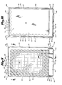
- FIGS. 1. 2, 3 and 4 show the assay cartridge in its completely assembled form.
- FIGS. 5, 6, 7 and 8 show the base plate prior to such assembly.
- FIGS. 9, 10, 11, 12 and 13 show the top plate and the rear, front and first and second walls prior to assembly.
- Base plate 10 has a substantially rectangular shape when viewed from the perspective of FIGS. 5 and 6. With general reference to FIGS. 2, 5, 6, 7 and 8, base plate 10 has rear 11, front 12 and first 13 and second 14 lateral surfaces. The surfaces are substantially flat. Base plate 10 has first corner surface 15 and second corner surface 16. These corner surfaces are substantially flat. First corner surface 15 is located between first lateral surface 13 and front lateral surface 12. Second corner surface 16 is.located between second lateral surface 14 and front lateral surface 12.
- Base plate 10 has raised ridge 17 as shown in FIGS. 6 and 7. Raised ridge 17 runs substantially along the lower periphery of front 12, rear 11, first 13 and second 14 lateral surfaces and first 15 and second 16 corner surfaces. Base plate 10 has underside 18 and channel 19 located along the outer periphery of the base plate underside 1B and between base plate underside 18 and base plate ridge 17.
- Base plate 10 has seating channels 21 formed by outer ridge 23 and inner ridge 22 as shown in FIGS. 5 and 7.
- Base plate 10 further has a plurality of support posts 25 also as shown in FIGS. 5 and 7.
- Base plate 10 still further has port 26 having opening 27 through base plate 10.
- Port 26 in the preferred embodiment is a tube which extends above base plate 10 as shown in FIGS. 7 and 8.
- Base plate 10 has finger grips 29 and 30 which are made up of a plurality of raised finger grip ridges 31.
- Top plate 35 is shown in FIGS. 9, 10. 11, 12 and 13.
- Top plate 35 has a substantially rectangular shape as shown in FIGS. 9 and 10.
- Top plate 35 has top side 36 and underside 37.
- Top plate 35 has a plurality of wells 39 located on its top side 36.
- Wells 39 are adjacent to one another and aligned in a geometric pattern as shown in FIGS. 9, 10 and 12. In the preferred embodiment, an eight by twelve matrix of wells yields a 96 well assay cartridge.
- Each well 39 has a hole 40 at its bottom which extends to underside 37 of top plate 35.
- Wells 39 each have an upper wall 41 which has a cylindrical shape and a lower wall 42 having the shape of an inverted frustum.
- Top plate 35 has rear 48, front 49 and first 50 and second 51 lateral surfaces. These lateral surfaces are substantially flat. Top plate 35 also has first 52 and second 53 corner surfaces. First corner surface 52 is located between first lateral surface 50 and front lateral surface 49. Second corner surface 53 is located between second lateral surface 51 and front lateral surface 49. Top plate 35 further has raised ridge 55 located along the upper periphery of front 49, rear 48, first 50 and second 51 lateral surfaces and first 52 and second 53 corner surfaces.
- Top plate 35 has two extended flat areas 58 and 59 of base 45 which are useful for placing decals on the cartridge or for placing a writing surface thereon for allowing information to be written onto the top of the plate.
- Top plate 35 has finger grips 60 and 61 which are constructed of a plurality of finger grip ridges 62.
- rear 65, front 66 and first 67 and second 68 walls are shown. These walls are serially joined to one another. This is illustrated by second wall 68 being joined to front wall 66 at juncture 69. These joined walls have a substantially rectangular cross-section as shown in FIG. 10. In the preferred embodiment, walls 65, 66, 67 and 68 are shown as joined to top plate 35 prior to assembly of the cartridge. This is illustrated by rear wall 65 being joined to top plate 35 at juncture 70 as shown in FIGS. 11 and 12.
- Filter membrane 71 is shown in FIGS. 10 and 12. Filter membrane 71 is positioned against the portion of underside 37 of top plate 35 to which well holes 40 extend. In the preferred embodiment, filter membrane 71 is joined to this portion of underside 37. Filter membrane 71 thus forms a seal around the periphery of each well hole 40. Filter membrane 71 is the floor of assay wells 39. In the preferred embodiment the filter membrane comprises a single filter unit. This filter unit is shown positioned against the entire portion of underside 37 to which well holes extend. In the alternative, the filter membrane may comprise a unit having holes in it where the unit holes do not align themselves with well holes 40. As a further alternative, the filter membrane may also comprise a plurality of distinct filter units where any given unit is positioned against only some of the well holes but where every well hole has some unit positioned against it.
- the assay cartridge may be assembled as follows. Seating channels 21 of base plate 10 shown in FIGS. 5 and 7 receive lower end 75 of rear 65, front 66, first 67 and second 68 walls of top plate 35 as shown in FIGS. 10, 11 and 12. The assembled assay cartridge is shown in FIG. 4 where channel 21 has received the lower end of rear wall 65 and front wall 66.
- top plate 35 is located opposite to and substantially parallel to base plate 10 as shown in FIG. 4.
- the serially joined rear, front, first and second walls are positioned between base plate 10 and top plate 35. These walls are joined to top plate 35 at juncture 70 as described above, and they are joined to base plate 10 at channel 21 as described immediately above.
- This joining of the walls to base plate 10 and top plate 35 effectively forms a sealed waste reservoir 76 which is located beneath wells 39 of top plate 35 and inside joined base plate 10, top plate 35 and the four walls. Reducing the pressure in waste reservoir 76 relative to the pressure over the wells will cause fluid in the wells to pass through filter membrane 71 and into the waste reservoir 76. Fluids passing into waste reservoir 76, i.e. waste products, will be retained in waste reservoir 76 upon a suitable choice of volume for the reservoir and an appropriate choice of the extent to which port 26 extends above base plate 10.
- Rear 65, front 66, first 67 and second 68 walls have respectively rear 76, front 77, first 78 and second 79 lateral surfaces. These lateral surfaces are substantially flat as shown in FIGS. 10, 11 and 12.
- rear base plate lateral surface 11, rear top.plate lateral surface 48 and rear wall lateral surface 76 are contiguous and substantially parallel.
- Front base plate lateral surface 12, front top plate lateral surface 49 and front wall lateral surface 77 are contiguous and substantially parallel.
- First base plate lateral surface 13, first top plate lateral surface 50 and first wall lateral surface 78 are contiguous and substantially parallel.
- Second base plate lateral surface 14, second top plate lateral surface 51 and second wall lateral surface 79 are contiguous and substantially parallel.
- Rear wall lateral surface 76 is laterally recessed relative to rear base plate lateral surface 11 and rear top plate lateral surface 48 as shown in FIG. 4.
- Front wall lateral surface 77 is laterally recessed relative to front base plate lateral surface 12 and front top plate lateral surface 49 as also illustrated in FIG. 4.
- first wall lateral surface 78 is laterally recessed relative to first base plate lateral surface 13 and first top plate lateral surface 50.
- Second wall lateral surface 79 is laterally recessed relative to second base plate lateral surface 14 and second top plate lateral surface 51.
- the assay cartridge may have rear 82 and front 83 centering pegs. These pegs extend laterally outward respectively from rear 76 and front 77 wall lateral surfaces. Rear 82 and front 83 centering pegs are substantially opposed to one another as shown in the preferred embodiment. These centering pegs aid an automated device in maintaining register over the assay cartridge.
- Top plate raised ridge 55 and base plate raised ridge 17 have substantially similar configurations.
- top plate raised ridge 55 has slightly smaller dimensions than base plate raised ridge 17. This allows stable stacking of assay cartridges in that the top plate raised ridge of an assay cartridge will mate with the base plate raised ridge of the assay cartridge stacked on top of it.
- Base plate 10 also has channel 19 as a further aid in receiving and mating with a top plate raised ridge 55.
- ridge 23 of top plate 35 has a substantially similar configuration to ridge 55 of base plate 10, but ridge 23 is laterally recessed relative to ridge 55.
- Base plate 10 and top plate 35 are injection-molded from plastic.
- the preferred plastic material is acrylic but other plastic materials such as, for example, polystyrene or polycarbonate could have been used as well.
- the filter membrane may have a pore size of about 10 microns or less depending upon the choice of solid phase. 0.2 microns is preferred in the case where the solid phase consists of beads sized about 0.2 microns. A pore size of 5-10 microns may be appropriate for a solid phase consisting of cells or other matter such as that discussed above.
- the filter membrane in the preferred embodiment is cellulose acetate, but nitro cellulose, polyvinyladine floride, polyvinyl chloride, teflon, polysulfone, polyester, polycarbonate, paper or glass fiber may, for example, also be used. These materials may be used as the filter membrane without pre-treatment.
- the hydrophilic/hydrophobic quality of the filter may be controlled in order to prevent seepage of fluids through the filter due to head pressure alone when no reduced pressure is applied to the waste reservoir.
- the hydrophilic/hydrophobic quality of the filter membrane may be controlled in known ways such as, for example, treating the filter with a surfactant.
- the filter may be hydrophilic.
- the filter may be hydrophobic.
- the filter may be hydrophobic.
- the filter may be hydrophobic.
- the filter may be hydrophobic.
- the well hole has a diameter of approximately 2 mm
- the upper wall of the well has a diameter of about 6.9 mm
- the well has a total depth from the top of the upper wall to the hole of about 4.25 mm.
- the filter membrane is joined to the top plate by placing the filter membrane into the mold prior to injecting and molding the plastic into the form of a top plate.
- the walls and base plate may be joined together ultrasonically where causing the top plate to vibrate in turn causes heat to be generated at the point of contact. Upon sufficient heat being generated at the point of contact, the lower end of the four side walls will fuse with the base plate channel receiving the lower end of the four side walls.
- a seal could be formed using solvents or another source of heat.
- the side walls could be joined to the base plate at the molding stage and the side walls subsequently joined to the top plate ultrasonically. Still further alternatives in joining the side walls to one another and to the base plate and top plate are intended to come within the spirit of the present invention.
Landscapes
- Health & Medical Sciences (AREA)
- Chemical & Material Sciences (AREA)
- Engineering & Computer Science (AREA)
- Immunology (AREA)
- Life Sciences & Earth Sciences (AREA)
- Hematology (AREA)
- Chemical Kinetics & Catalysis (AREA)
- Biomedical Technology (AREA)
- Water Supply & Treatment (AREA)
- General Health & Medical Sciences (AREA)
- Analytical Chemistry (AREA)
- Molecular Biology (AREA)
- Urology & Nephrology (AREA)
- Medicinal Chemistry (AREA)
- Biotechnology (AREA)
- Physics & Mathematics (AREA)
- Microbiology (AREA)
- Biochemistry (AREA)
- Cell Biology (AREA)
- General Physics & Mathematics (AREA)
- Pathology (AREA)
- Clinical Laboratory Science (AREA)
- Food Science & Technology (AREA)
- Apparatus Associated With Microorganisms And Enzymes (AREA)
- Separation Using Semi-Permeable Membranes (AREA)
- Devices For Use In Laboratory Experiments (AREA)
- Eye Examination Apparatus (AREA)
- Saccharide Compounds (AREA)
- Magnetic Resonance Imaging Apparatus (AREA)
- Automatic Analysis And Handling Materials Therefor (AREA)
- Investigating Or Analysing Biological Materials (AREA)
Priority Applications (1)
| Application Number | Priority Date | Filing Date | Title |
|---|---|---|---|
| AT84108246T ATE70365T1 (de) | 1983-07-15 | 1984-07-13 | Testsatz. |
Applications Claiming Priority (2)
| Application Number | Priority Date | Filing Date | Title |
|---|---|---|---|
| US06/514,170 US4704255A (en) | 1983-07-15 | 1983-07-15 | Assay cartridge |
| US514170 | 1983-07-15 |
Publications (3)
| Publication Number | Publication Date |
|---|---|
| EP0131934A2 true EP0131934A2 (de) | 1985-01-23 |
| EP0131934A3 EP0131934A3 (en) | 1987-12-16 |
| EP0131934B1 EP0131934B1 (de) | 1991-12-11 |
Family
ID=24046084
Family Applications (1)
| Application Number | Title | Priority Date | Filing Date |
|---|---|---|---|
| EP84108246A Expired - Lifetime EP0131934B1 (de) | 1983-07-15 | 1984-07-13 | Testsatz |
Country Status (5)
| Country | Link |
|---|---|
| US (1) | US4704255A (de) |
| EP (1) | EP0131934B1 (de) |
| JP (1) | JPS60100054A (de) |
| AT (1) | ATE70365T1 (de) |
| DE (1) | DE3485333D1 (de) |
Cited By (37)
| Publication number | Priority date | Publication date | Assignee | Title |
|---|---|---|---|---|
| DE3618884A1 (de) * | 1985-06-10 | 1986-12-11 | Bio-Rad Laboratories, Inc., Richmond, Calif. | Testplattenanordnung, die diskrete bereiche auf einer mikroporoesen membran mit einer geringen randverformung bildet |
| WO1986007606A1 (en) * | 1985-06-18 | 1986-12-31 | Genemed Technology, Inc. | Multiwell test plate |
| EP0244207A1 (de) * | 1986-04-30 | 1987-11-04 | Toray Industries, Inc. | Nachweismethode und Gerät |
| EP0198413A3 (en) * | 1985-04-12 | 1987-12-23 | E.I. Du Pont De Nemours And Company | Rapid assay processor |
| EP0272043A3 (en) * | 1986-12-15 | 1989-04-05 | Pall Corporation | Diagnostic device |
| EP0302933A4 (de) * | 1987-02-24 | 1990-04-10 | Bionique Lab Inc | Wegwerfimmuntestsatz für draussen und für labor. |
| FR2638101A1 (fr) * | 1988-10-21 | 1990-04-27 | Biocom Sa | Dispositif de filtration parallele d'une pluralite d'echantillons avec controle automatique des volumes filtres et du colmatage ainsi qu'avec indexation du filtre, et procede de filtration |
| EP0359249A3 (de) * | 1988-09-16 | 1990-06-20 | Amicon Inc. | Mikrofiltration und Verfahren |
| WO1990008313A1 (en) * | 1989-01-17 | 1990-07-26 | Molecular Devices Corporation | Analytical work station |
| US5006309A (en) * | 1988-04-22 | 1991-04-09 | Abbott Laboratories | Immunoassay device with liquid transfer between wells by washing |
| US5089424A (en) * | 1988-06-14 | 1992-02-18 | Abbott Laboratories | Method and apparatus for heterogeneous chemiluminescence assay |
| US5149622A (en) * | 1985-10-04 | 1992-09-22 | Abbott Laboratories | Solid phase analytical device and method for using same |
| US5198368A (en) * | 1988-04-22 | 1993-03-30 | Abbott Laboratories | Methods for performing a solid-phase immunoassay |
| EP0542655A1 (de) * | 1991-11-12 | 1993-05-19 | Institut Jacques Boy | Vorrichtung zur Trennung und Bestimmung der Erythrozyt-Agglutinate in einem Schritt |
| EP0596482A1 (de) * | 1992-11-04 | 1994-05-11 | Millipore Corporation | Mehrfachlochtestvorrichtung |
| EP0604287A1 (de) * | 1992-12-24 | 1994-06-29 | Laboratoires De Biologie Vegetale Yves Rocher | Verfahren und Vorrichtung zur Prüfung von Zellreaktivität gegen Produkte |
| US5441894A (en) * | 1993-04-30 | 1995-08-15 | Abbott Laboratories | Device containing a light absorbing element for automated chemiluminescent immunoassays |
| WO1995024648A1 (en) * | 1994-03-10 | 1995-09-14 | Fodstad Oeystein | Method and device for detection of specific target cells in specialized or mixed cell populations and solutions containing mixed cell populations |
| EP0776700A1 (de) * | 1995-12-08 | 1997-06-04 | The Institute of Physical and Chemical Research ( RIKEN) | Verfahren zur Reinigung und Übertragung von sequenzierten DNA-Proben nach Trenn-/Feststellungssystem und Platte dafür |
| WO1997036681A1 (en) * | 1996-04-03 | 1997-10-09 | The Perkin-Elmer Corporation | Device and method for multiple analyte detection |
| DE19712484A1 (de) * | 1997-03-25 | 1998-10-01 | Greiner Gmbh | Microplatte mit transparentem Boden |
| WO2000000830A1 (de) * | 1998-06-29 | 2000-01-06 | Sension, Biologische Detektions- Und Schnelltestsysteme Gmbh | Kombi-vorrichtung zur simultanen durchführung von immunfiltrationstests |
| US6184043B1 (en) | 1992-09-14 | 2001-02-06 | FODSTAD øYSTEIN | Method for detection of specific target cells in specialized or mixed cell population and solutions containing mixed cell populations |
| DE10002666A1 (de) * | 2000-01-21 | 2001-08-02 | Greiner Bio One Gmbh | Behälter zur Lagerung von biologischem Material |
| US6338802B1 (en) | 1998-10-29 | 2002-01-15 | Pe Corporation (Ny) | Multi-well microfiltration apparatus |
| US6419827B1 (en) | 1998-10-29 | 2002-07-16 | Applera Corporation | Purification apparatus and method |
| WO2001011374A3 (en) * | 1999-08-06 | 2002-08-08 | Thermo Biostar Inc | An automated point of care detection system including complete sample processing capabilities |
| US6498240B1 (en) | 1999-09-17 | 2002-12-24 | Millipore Corporation | Method for sequencing reaction cleanup by constant pressure diffential ultrafiltration |
| DE10160975A1 (de) * | 2001-12-10 | 2003-06-18 | Univ Schiller Jena | Probenplatte zur Verwendung in Dialysesystemen |
| US6680301B2 (en) | 1994-09-08 | 2004-01-20 | Photocure As | Transfer of molecules into the cytosol of cells |
| US6825047B1 (en) | 1996-04-03 | 2004-11-30 | Applera Corporation | Device and method for multiple analyte detection |
| US7198787B2 (en) | 1996-03-13 | 2007-04-03 | Oystein Fodstad | Method of killing target cells in harvested cell populations with one or more immuno-toxins |
| US7211224B2 (en) | 2002-05-23 | 2007-05-01 | Millipore Corporation | One piece filtration plate |
| US7235406B1 (en) | 1996-04-03 | 2007-06-26 | Applera Corporation | Nucleic acid analysis device |
| US7244622B2 (en) | 1996-04-03 | 2007-07-17 | Applera Corporation | Device and method for multiple analyte detection |
| DE19948087B4 (de) * | 1999-10-06 | 2008-04-17 | Evotec Ag | Verfahren zur Herstellung eines Reaktionssubstrats |
| WO2012066499A1 (en) | 2010-11-17 | 2012-05-24 | Diagcor Bioscience Incorporation Limited | Flow-through apparatus |
Families Citing this family (69)
| Publication number | Priority date | Publication date | Assignee | Title |
|---|---|---|---|---|
| US6365368B1 (en) * | 1985-05-10 | 2002-04-02 | Igen International, Inc. | Rapid method for the detection and quantification of microbes in water |
| US4777021A (en) * | 1986-04-25 | 1988-10-11 | Richard K. Wertz | Manifold vacuum device for biochemical and immunological uses |
| US4895706A (en) * | 1986-10-28 | 1990-01-23 | Costar Corporation | Multi-well filter strip and composite assemblies |
| US4789526A (en) * | 1986-12-15 | 1988-12-06 | Pall Corporation | Vacuum diagnostic device |
| US5202267A (en) * | 1988-04-04 | 1993-04-13 | Hygeia Sciences, Inc. | Sol capture immunoassay kit and procedure |
| US4919894A (en) * | 1988-05-23 | 1990-04-24 | Robert Daniel | Multiple sample holder indexing means and method of using same |
| US6448091B1 (en) * | 1988-11-03 | 2002-09-10 | Igen International, Inc. | Method and apparatus for improved luminescence assays using particle concentration chemiluminescence detection |
| ATE117804T1 (de) * | 1989-06-05 | 1995-02-15 | Janssen Pharmaceutica Nv | Festphasen-test zur verwendung mit einem physikalischen entwickler. |
| US5155049A (en) * | 1989-08-22 | 1992-10-13 | Terrapin Technologies, Inc. | Blotting technique for membrane assay |
| US5227290A (en) * | 1990-08-29 | 1993-07-13 | Pocock Douglas A | Method for conducting diagnostic assays |
| US5409832A (en) * | 1990-08-29 | 1995-04-25 | Stratecon Diagnostics International | Membrane holder for use in an assay device |
| US5108603A (en) * | 1991-04-04 | 1992-04-28 | Life Technologies, Inc. | Self-contained vacuum clamped multi-sample media filtration apparatus and method |
| US5227137A (en) * | 1991-04-04 | 1993-07-13 | Nicholson Precision Instruments Inc. | Vacuum clamped multi-sample filtration apparatus |
| US5205989A (en) * | 1991-09-18 | 1993-04-27 | Minnesota Mining And Manufacturing Company | Multi-well filtration apparatus |
| US5329461A (en) * | 1992-07-23 | 1994-07-12 | Acrogen, Inc. | Digital analyte detection system |
| EP0583980A1 (de) * | 1992-08-20 | 1994-02-23 | Eli Lilly And Company | Verfahren zur Herstellung von monoklonalen Antikörpern aus Kaninchen |
| US5354692A (en) * | 1992-09-08 | 1994-10-11 | Pacific Biotech, Inc. | Analyte detection device including a hydrophobic barrier for improved fluid flow |
| WO1994008716A1 (en) * | 1992-10-09 | 1994-04-28 | Baxter Diagnostics Inc. | Assay cartridge |
| US5342581A (en) * | 1993-04-19 | 1994-08-30 | Sanadi Ashok R | Apparatus for preventing cross-contamination of multi-well test plates |
| US6258325B1 (en) * | 1993-04-19 | 2001-07-10 | Ashok Ramesh Sanadi | Method and apparatus for preventing cross-contamination of multi-well test plates |
| WO1998046981A1 (en) * | 1997-04-14 | 1998-10-22 | Ljl Biosystems | Microplate having wells with elevated bottoms |
| US6171780B1 (en) * | 1997-06-02 | 2001-01-09 | Aurora Biosciences Corporation | Low fluorescence assay platforms and related methods for drug discovery |
| US6391241B1 (en) | 1997-06-06 | 2002-05-21 | Corning Incorporated | Method of manufacture for a multiwell plate and/or filter plate |
| US20030054543A1 (en) * | 1997-06-16 | 2003-03-20 | Lafferty William Michael | Device for moving a selected station of a holding plate to a predetermined location for interaction with a probe |
| US6071748A (en) * | 1997-07-16 | 2000-06-06 | Ljl Biosystems, Inc. | Light detection device |
| US6258326B1 (en) | 1997-09-20 | 2001-07-10 | Ljl Biosystems, Inc. | Sample holders with reference fiducials |
| US6097025A (en) * | 1997-10-31 | 2000-08-01 | Ljl Biosystems, Inc. | Light detection device having an optical-path switching mechanism |
| US6469311B1 (en) | 1997-07-16 | 2002-10-22 | Molecular Devices Corporation | Detection device for light transmitted from a sensed volume |
| US6082185A (en) * | 1997-07-25 | 2000-07-04 | Research International, Inc. | Disposable fluidic circuit cards |
| WO2000050877A1 (en) | 1999-02-23 | 2000-08-31 | Ljl Biosystems, Inc. | Frequency-domain light detection device |
| US6576476B1 (en) | 1998-09-02 | 2003-06-10 | Ljl Biosystems, Inc. | Chemiluminescence detection method and device |
| US6825921B1 (en) | 1999-11-10 | 2004-11-30 | Molecular Devices Corporation | Multi-mode light detection system |
| US6297018B1 (en) | 1998-04-17 | 2001-10-02 | Ljl Biosystems, Inc. | Methods and apparatus for detecting nucleic acid polymorphisms |
| US6992761B2 (en) | 1997-09-20 | 2006-01-31 | Molecular Devices Corporation | Broad range light detection system |
| US6982431B2 (en) | 1998-08-31 | 2006-01-03 | Molecular Devices Corporation | Sample analysis systems |
| US6326605B1 (en) | 1998-02-20 | 2001-12-04 | Ljl Biosystems, Inc. | Broad range light detection system |
| WO1999023475A1 (en) * | 1997-10-31 | 1999-05-14 | Dade Behring Inc. | Chromogenic and turbidimetric assay device |
| AU3649199A (en) | 1998-04-17 | 1999-11-08 | Ljl Biosystems, Inc. | Sample-holding devices and systems |
| AU5223899A (en) * | 1998-07-27 | 2000-02-21 | Ljl Biosystems, Inc. | Apparatus and methods for spectroscopic measurements |
| AU5667599A (en) | 1998-07-27 | 2000-02-21 | Ljl Biosystems, Inc. | Apparatus and methods for time-resolved spectroscopic measurements |
| US6906292B2 (en) | 1998-10-29 | 2005-06-14 | Applera Corporation | Sample tray heater module |
| US6896849B2 (en) | 1998-10-29 | 2005-05-24 | Applera Corporation | Manually-operable multi-well microfiltration apparatus and method |
| US6486401B1 (en) | 1999-02-22 | 2002-11-26 | Tekcel, Inc. | Multi well plate cover and assembly |
| USD422689S (en) * | 1999-09-07 | 2000-04-11 | Yiu Felix H | Laboratory evaporator device |
| US6464943B1 (en) | 1999-09-07 | 2002-10-15 | Felix H. Yiu | Solid phase evaporator device |
| US7033840B1 (en) | 1999-11-09 | 2006-04-25 | Sri International | Reaction calorimeter and differential scanning calorimeter for the high-throughput synthesis, screening and characterization of combinatorial libraries |
| EP1272255B1 (de) * | 2000-04-10 | 2008-12-03 | Millipore Corporation | Mechanische verriegelung für filter |
| DE10035750A1 (de) * | 2000-07-22 | 2002-02-07 | Forschungszentrum Juelich Gmbh | Vorrichtung mit einer Vielzahl von Probenkammern zur Behandlung von Zellen und zur Analyse mittels lichterzeugender Verfahren sowie Filterverbund |
| US20020132360A1 (en) | 2000-11-17 | 2002-09-19 | Flir Systems Boston, Inc. | Apparatus and methods for infrared calorimetric measurements |
| US6821787B2 (en) | 2000-11-17 | 2004-11-23 | Thermogenic Imaging, Inc. | Apparatus and methods for infrared calorimetric measurements |
| US7776571B2 (en) * | 2000-12-12 | 2010-08-17 | Autogenomics, Inc. | Multi-substrate biochip unit |
| US6896848B1 (en) | 2000-12-19 | 2005-05-24 | Tekcel, Inc. | Microplate cover assembly |
| US6627432B2 (en) | 2001-02-28 | 2003-09-30 | Dade Behring Inc. | Liquid flow and control in a biological test array |
| US6645737B2 (en) | 2001-04-24 | 2003-11-11 | Dade Microscan Inc. | Method for maintaining test accuracy within a microbiological test array |
| JP3669996B2 (ja) * | 2001-06-14 | 2005-07-13 | ミリポア・コーポレイション | マルチウェル試験装置のための位置決めピン |
| US6896144B2 (en) * | 2001-06-25 | 2005-05-24 | Innovative Microplate | Filtration and separation apparatus and method of assembly |
| GB2377990B (en) * | 2001-07-17 | 2003-11-12 | Vivascience Ltd | Device for simultaneous processing of discrete quantities of flowable material |
| JP3712677B2 (ja) * | 2002-01-29 | 2005-11-02 | 富士写真フイルム株式会社 | 生化学解析用ユニット |
| US6918738B2 (en) | 2002-03-11 | 2005-07-19 | Diversa Corporation | Stackable sample holding plate with robot removable lid |
| US6798520B2 (en) * | 2002-03-22 | 2004-09-28 | Diversa Corporation | Method for intensifying the optical detection of samples that are held in solution in the through-hole wells of a holding tray |
| US6716350B2 (en) * | 2002-05-03 | 2004-04-06 | Millipore Corporation | Microplate protective tray undercover |
| US8202439B2 (en) * | 2002-06-05 | 2012-06-19 | Panasonic Corporation | Diaphragm and device for measuring cellular potential using the same, manufacturing method of the diaphragm |
| EP1783202B1 (de) * | 2004-08-25 | 2013-10-02 | Panasonic Corporation | Sonde zum messen des elektrischen potentials einer zelle |
| EP1963854B1 (de) | 2005-12-21 | 2021-02-03 | Meso Scale Technologies, LLC | Assay-vorrichtungen, -verfahren und -reagenzien |
| CN105115949B (zh) * | 2005-12-21 | 2018-06-22 | 梅索斯卡莱科技公司 | 分析装置、方法和试剂 |
| US8048047B2 (en) * | 2006-06-23 | 2011-11-01 | Novartis Ag | Surgical cassette with improved air filtering |
| KR20090056980A (ko) * | 2006-08-15 | 2009-06-03 | 더 거번먼트 오브 더 유나이티드 스테이츠 오브 아메리카, 레프리젠티드 바이 더 세크러테리 오브 더 네이비 | 평면 기판에 유체 셀을 부착하기 위한 방법 및 장치 |
| USD771834S1 (en) * | 2015-04-28 | 2016-11-15 | University Of British Columbia | Microfluidic cartridge |
| ES2781880T3 (es) * | 2017-08-18 | 2020-09-08 | Ctc Analytics Ag | Cartucho para ensayos químicos o biológicos |
Family Cites Families (26)
| Publication number | Priority date | Publication date | Assignee | Title |
|---|---|---|---|---|
| US30562A (en) * | 1860-11-06 | Washing-machine | ||
| US3283943A (en) * | 1964-05-15 | 1966-11-08 | Cargnelutti Italo | Stacking container |
| US3649464A (en) * | 1969-12-05 | 1972-03-14 | Microbiological Ass Inc | Assay and culture tray |
| US3888770A (en) * | 1971-10-21 | 1975-06-10 | Shlomo Avital | Plural-sample filter device |
| US3730352A (en) * | 1971-12-06 | 1973-05-01 | New Brunswick Scientific Co | Filtration apparatus |
| US4056724A (en) * | 1975-02-27 | 1977-11-01 | International Diagnostic Technology | Fluorometric system, method and test article |
| US3992631A (en) * | 1975-02-27 | 1976-11-16 | International Diagnostic Technology, Inc. | Fluorometric system, method and test article |
| US4189466A (en) * | 1975-09-19 | 1980-02-19 | Technical Research Affiliates, Inc. | Detection of rheumatoid factor by antibody sensitized microbial particles |
| US4201763A (en) * | 1975-10-09 | 1980-05-06 | Bio-Rad Laboratories, Inc. | Solid phase immunofluorescent assay method |
| US3999948A (en) * | 1975-11-03 | 1976-12-28 | International Diagnostic Technology | Diagnostic reagent holder and method |
| US4038149A (en) * | 1975-12-31 | 1977-07-26 | Linbro Scientific, Inc. | Laboratory trays with lockable covers |
| US4020151A (en) * | 1976-02-17 | 1977-04-26 | International Diagnostic Technology, Inc. | Method for quantitation of antigens or antibodies on a solid surface |
| US4025310A (en) * | 1976-05-28 | 1977-05-24 | International Diagnostic Technology, Inc. | Method for reading a wet fluorescent surface |
| US4144452A (en) * | 1976-07-08 | 1979-03-13 | International Diagnostic Technology, Inc. | Fluorometric system, method and test article |
| US4167875A (en) * | 1976-08-05 | 1979-09-18 | Meakin John C | Filtration method and apparatus |
| US4090850A (en) * | 1976-11-01 | 1978-05-23 | E. R. Squibb & Sons, Inc. | Apparatus for use in radioimmunoassays |
| US4184849A (en) * | 1977-12-05 | 1980-01-22 | Technicon Instruments Corporation | Mixed agglutination |
| US4163779A (en) * | 1978-01-09 | 1979-08-07 | International Diagnostic Technology, Inc. | Test for quantitation of immunoglobulin and identification of abnormal immunoglobulin |
| US4427415A (en) * | 1979-01-05 | 1984-01-24 | Cleveland Patrick H | Manifold vacuum biochemical test method and device |
| USRE30562E (en) | 1979-02-22 | 1981-03-31 | Immunological testing devices | |
| US4238449A (en) * | 1979-05-21 | 1980-12-09 | International Diagnostic Technology, Inc. | Reagent holder |
| US4295199A (en) * | 1979-10-22 | 1981-10-13 | Bio-Rad Laboratories, Inc. | Automatic fluorometer and data processor for performing fluorescent immunoassays |
| US4259289A (en) * | 1979-10-22 | 1981-03-31 | Bio-Rad Laboratories, Inc. | Apparatus for retrieving liquid samples from test tubes |
| US4271123A (en) * | 1979-10-22 | 1981-06-02 | Bio-Rad Laboratories, Inc. | Automated system for performing fluorescent immunoassays |
| US4373642A (en) * | 1980-12-04 | 1983-02-15 | Westinghouse Electric Corp. | Material handling tote |
| SE8102316L (sv) * | 1981-04-10 | 1982-10-11 | Pharmacia Diagnostics Ab | Anordning for genomforande av analyser |
-
1983
- 1983-07-15 US US06/514,170 patent/US4704255A/en not_active Expired - Lifetime
-
1984
- 1984-07-13 DE DE8484108246T patent/DE3485333D1/de not_active Expired - Lifetime
- 1984-07-13 AT AT84108246T patent/ATE70365T1/de not_active IP Right Cessation
- 1984-07-13 EP EP84108246A patent/EP0131934B1/de not_active Expired - Lifetime
- 1984-07-16 JP JP59147435A patent/JPS60100054A/ja active Granted
Cited By (71)
| Publication number | Priority date | Publication date | Assignee | Title |
|---|---|---|---|---|
| EP0198413A3 (en) * | 1985-04-12 | 1987-12-23 | E.I. Du Pont De Nemours And Company | Rapid assay processor |
| US4753775A (en) * | 1985-04-12 | 1988-06-28 | E. I. Du Pont De Nemours And Company | Rapid assay processor |
| DE3618884A1 (de) * | 1985-06-10 | 1986-12-11 | Bio-Rad Laboratories, Inc., Richmond, Calif. | Testplattenanordnung, die diskrete bereiche auf einer mikroporoesen membran mit einer geringen randverformung bildet |
| WO1986007606A1 (en) * | 1985-06-18 | 1986-12-31 | Genemed Technology, Inc. | Multiwell test plate |
| US5149622A (en) * | 1985-10-04 | 1992-09-22 | Abbott Laboratories | Solid phase analytical device and method for using same |
| EP0244207A1 (de) * | 1986-04-30 | 1987-11-04 | Toray Industries, Inc. | Nachweismethode und Gerät |
| EP0272043A3 (en) * | 1986-12-15 | 1989-04-05 | Pall Corporation | Diagnostic device |
| EP0302933A4 (de) * | 1987-02-24 | 1990-04-10 | Bionique Lab Inc | Wegwerfimmuntestsatz für draussen und für labor. |
| US5006309A (en) * | 1988-04-22 | 1991-04-09 | Abbott Laboratories | Immunoassay device with liquid transfer between wells by washing |
| US5198368A (en) * | 1988-04-22 | 1993-03-30 | Abbott Laboratories | Methods for performing a solid-phase immunoassay |
| US5089424A (en) * | 1988-06-14 | 1992-02-18 | Abbott Laboratories | Method and apparatus for heterogeneous chemiluminescence assay |
| US5108704A (en) * | 1988-09-16 | 1992-04-28 | W. R. Grace & Co.-Conn. | Microfiltration apparatus with radially spaced nozzles |
| EP0359249A3 (de) * | 1988-09-16 | 1990-06-20 | Amicon Inc. | Mikrofiltration und Verfahren |
| US5190666A (en) * | 1988-10-21 | 1993-03-02 | Biocom S.A. | Method and apparatus for filtering a plurality of samples through a filter with indexing of the filter |
| WO1990004445A1 (fr) * | 1988-10-21 | 1990-05-03 | Biocom | Dispositif de filtration parallele d'une pluralite d'echantillons avec controle automatique des volumes filtres et du colmatage ainsi qu'avec indexation du filtre, et procede de filtration |
| FR2638101A1 (fr) * | 1988-10-21 | 1990-04-27 | Biocom Sa | Dispositif de filtration parallele d'une pluralite d'echantillons avec controle automatique des volumes filtres et du colmatage ainsi qu'avec indexation du filtre, et procede de filtration |
| WO1990008313A1 (en) * | 1989-01-17 | 1990-07-26 | Molecular Devices Corporation | Analytical work station |
| EP0542655A1 (de) * | 1991-11-12 | 1993-05-19 | Institut Jacques Boy | Vorrichtung zur Trennung und Bestimmung der Erythrozyt-Agglutinate in einem Schritt |
| FR2688311A1 (fr) * | 1991-11-12 | 1993-09-10 | Boy Inst Jacques | Procede pour la mise en evidence d'agglutinats erythrocytaires. |
| USRE43979E1 (en) | 1992-09-14 | 2013-02-05 | Abbott Laboratories | Method for detection of specific target cells in specialized or mixed cell population and solutions containing mixed cell populations |
| US6184043B1 (en) | 1992-09-14 | 2001-02-06 | FODSTAD øYSTEIN | Method for detection of specific target cells in specialized or mixed cell population and solutions containing mixed cell populations |
| US6893881B1 (en) | 1992-09-14 | 2005-05-17 | Abbott Laboratories, Inc. | Method for detection of specific target cells in specialized or mixed cell population and solutions containing mixed cell populations |
| EP0596482A1 (de) * | 1992-11-04 | 1994-05-11 | Millipore Corporation | Mehrfachlochtestvorrichtung |
| US5424213A (en) * | 1992-12-24 | 1995-06-13 | Laboratories De Biologie Vegetale Yves Rocher | Method for testing the reactivity of cells with respect to products |
| FR2700010A1 (fr) * | 1992-12-24 | 1994-07-01 | Rocher Yves Biolog Vegetale | Méthode et dispositif pour tester la réactivité de cellules à l'égard de produits. |
| EP0604287A1 (de) * | 1992-12-24 | 1994-06-29 | Laboratoires De Biologie Vegetale Yves Rocher | Verfahren und Vorrichtung zur Prüfung von Zellreaktivität gegen Produkte |
| US5441894A (en) * | 1993-04-30 | 1995-08-15 | Abbott Laboratories | Device containing a light absorbing element for automated chemiluminescent immunoassays |
| US6265229B1 (en) | 1994-03-10 | 2001-07-24 | Oystein Fodstad | Method and device for detection of specific target cells in specialized or mixed cell populations and solutions containing mixed cell populations |
| WO1995024648A1 (en) * | 1994-03-10 | 1995-09-14 | Fodstad Oeystein | Method and device for detection of specific target cells in specialized or mixed cell populations and solutions containing mixed cell populations |
| US6680301B2 (en) | 1994-09-08 | 2004-01-20 | Photocure As | Transfer of molecules into the cytosol of cells |
| US5856100A (en) * | 1995-12-08 | 1999-01-05 | The Institute Of Physical And Chemical Research | Method for purification and transfer to separation/detection systems of DNA sequencing samples and plates used therefor |
| EP0776700A1 (de) * | 1995-12-08 | 1997-06-04 | The Institute of Physical and Chemical Research ( RIKEN) | Verfahren zur Reinigung und Übertragung von sequenzierten DNA-Proben nach Trenn-/Feststellungssystem und Platte dafür |
| US7198787B2 (en) | 1996-03-13 | 2007-04-03 | Oystein Fodstad | Method of killing target cells in harvested cell populations with one or more immuno-toxins |
| US7381569B2 (en) | 1996-04-03 | 2008-06-03 | Applera Corporation | Device and method for multiple analyte detection |
| US7888108B2 (en) | 1996-04-03 | 2011-02-15 | Applied Biosystems, Llc | Device and method for multiple analyte detection |
| WO1997036681A1 (en) * | 1996-04-03 | 1997-10-09 | The Perkin-Elmer Corporation | Device and method for multiple analyte detection |
| AU706862B2 (en) * | 1996-04-03 | 1999-06-24 | Applied Biosystems, Llc | Device and method for multiple analyte detection |
| US8247219B2 (en) | 1996-04-03 | 2012-08-21 | Applied Biosystems, Llc | Device and method for multiple analyte detection |
| US8163538B2 (en) | 1996-04-03 | 2012-04-24 | Applied Biosystems, Llc | Device and method for multiple analyte detection |
| US8119423B2 (en) | 1996-04-03 | 2012-02-21 | Applied Biosystems, Llc | Device and method for multiple analyte detection |
| US8067226B2 (en) | 1996-04-03 | 2011-11-29 | Applied Biosystems, Llc | Device and method for multiple analyte detection |
| US8062883B2 (en) | 1996-04-03 | 2011-11-22 | Applied Biosystems, Llc | Device and method for multiple analyte detection |
| US7833711B2 (en) | 1996-04-03 | 2010-11-16 | Applied Biosystems, Llc | Device and method for multiple analyte detection |
| US7687280B2 (en) | 1996-04-03 | 2010-03-30 | Applied Biosystems, Llc | Device and method for multiple analyte detection |
| US7381570B2 (en) | 1996-04-03 | 2008-06-03 | Applera Corporation | Device and method for multiple analyte detection |
| US7381571B2 (en) | 1996-04-03 | 2008-06-03 | Applera Corporation | Device and method for analyte detection |
| US7244622B2 (en) | 1996-04-03 | 2007-07-17 | Applera Corporation | Device and method for multiple analyte detection |
| US6126899A (en) * | 1996-04-03 | 2000-10-03 | The Perkins-Elmer Corporation | Device for multiple analyte detection |
| US6825047B1 (en) | 1996-04-03 | 2004-11-30 | Applera Corporation | Device and method for multiple analyte detection |
| US6124138A (en) * | 1996-04-03 | 2000-09-26 | The Perkin-Elmer Corporation | Method for multiple analyte detection |
| US7235406B1 (en) | 1996-04-03 | 2007-06-26 | Applera Corporation | Nucleic acid analysis device |
| US6514464B1 (en) | 1997-03-25 | 2003-02-04 | Greiner Bio-One Gmbh | Micro plate with transparent base |
| DE19712484A1 (de) * | 1997-03-25 | 1998-10-01 | Greiner Gmbh | Microplatte mit transparentem Boden |
| US6503456B1 (en) | 1997-03-25 | 2003-01-07 | Greiner Bio-One Gmbh | Microplate with transparent base |
| DE19712484C2 (de) * | 1997-03-25 | 1999-07-08 | Greiner Gmbh | Microplatte mit transparentem Boden und Verfahren zu deren Herstellung |
| US8512652B2 (en) * | 1997-03-25 | 2013-08-20 | Greiner Bio-One Gmbh | Multiwell microplate with transparent bottom having a thickness less than 200 micrometers |
| WO2000000830A1 (de) * | 1998-06-29 | 2000-01-06 | Sension, Biologische Detektions- Und Schnelltestsysteme Gmbh | Kombi-vorrichtung zur simultanen durchführung von immunfiltrationstests |
| US6451261B1 (en) | 1998-10-29 | 2002-09-17 | Applera Corporation | Multi-well microfiltration apparatus |
| US6506343B1 (en) | 1998-10-29 | 2003-01-14 | Applera Corporation | Multi-well microfiltration apparatus and method for avoiding cross-contamination |
| US6338802B1 (en) | 1998-10-29 | 2002-01-15 | Pe Corporation (Ny) | Multi-well microfiltration apparatus |
| US6419827B1 (en) | 1998-10-29 | 2002-07-16 | Applera Corporation | Purification apparatus and method |
| CN100374863C (zh) * | 1999-08-06 | 2008-03-12 | 热生物之星公司 | 具有完全样品处理能力的医疗检测系统的自动测试装置 |
| WO2001011374A3 (en) * | 1999-08-06 | 2002-08-08 | Thermo Biostar Inc | An automated point of care detection system including complete sample processing capabilities |
| US6645722B2 (en) | 1999-09-17 | 2003-11-11 | Millipore Corporation | Method for sequencing reaction cleanup by constant differential pressure ultrafiltration |
| US6498240B1 (en) | 1999-09-17 | 2002-12-24 | Millipore Corporation | Method for sequencing reaction cleanup by constant pressure diffential ultrafiltration |
| DE19948087B4 (de) * | 1999-10-06 | 2008-04-17 | Evotec Ag | Verfahren zur Herstellung eines Reaktionssubstrats |
| DE10002666A1 (de) * | 2000-01-21 | 2001-08-02 | Greiner Bio One Gmbh | Behälter zur Lagerung von biologischem Material |
| DE10160975A1 (de) * | 2001-12-10 | 2003-06-18 | Univ Schiller Jena | Probenplatte zur Verwendung in Dialysesystemen |
| US7211224B2 (en) | 2002-05-23 | 2007-05-01 | Millipore Corporation | One piece filtration plate |
| WO2012066499A1 (en) | 2010-11-17 | 2012-05-24 | Diagcor Bioscience Incorporation Limited | Flow-through apparatus |
| EP2640519A4 (de) * | 2010-11-17 | 2016-11-16 | Diagcor Bioscience Inc Ltd | Durchlaufvorrichtung |
Also Published As
| Publication number | Publication date |
|---|---|
| JPH0564302B2 (de) | 1993-09-14 |
| DE3485333D1 (de) | 1992-01-23 |
| EP0131934B1 (de) | 1991-12-11 |
| ATE70365T1 (de) | 1991-12-15 |
| EP0131934A3 (en) | 1987-12-16 |
| JPS60100054A (ja) | 1985-06-03 |
| US4704255A (en) | 1987-11-03 |
Similar Documents
| Publication | Publication Date | Title |
|---|---|---|
| US4704255A (en) | Assay cartridge | |
| US5006309A (en) | Immunoassay device with liquid transfer between wells by washing | |
| US7871813B2 (en) | Diagnostic device and method | |
| CN103480438B (zh) | 用于临床诊断设备中的侧向流测定装置和使用它们的临床诊断设备的构型 | |
| US5116576A (en) | Device for analytical determinations | |
| US5746975A (en) | Apparatus for immunological analysis | |
| JP2907339B2 (ja) | 複数のポートを設けたアツセイデバイス | |
| EP2902784B1 (de) | Assayvorrichtung mit einem porösen medium | |
| US5188968A (en) | Method and reaction kit for agglutination detection | |
| JPH11316226A (ja) | 自動測定用カートリッジ及び自動測定法 | |
| JPS63167267A (ja) | ウエル型診断用プレート装置 | |
| JPH01502526A (ja) | 必要物が完備したイムノアツセイ要素 | |
| CN86103715A (zh) | 横向流动的鉴定设备 | |
| CN105241871A (zh) | 一种用于全血样品检测的磁微粒化学发光微流控芯片 | |
| US5427739A (en) | Apparatus for performing immunoassays | |
| US7629165B2 (en) | Diagnostic device and method | |
| US20260102774A1 (en) | Cellular cassettes for the collection, storage, and analysis of biological samples | |
| US20080277348A1 (en) | Liquid Exchange Method, Ingredient Extraction Method Using the Same, Composite Container and Autoanalyzer | |
| US5198368A (en) | Methods for performing a solid-phase immunoassay | |
| US20030235920A1 (en) | Diagnostic device and method | |
| EP0283613A2 (de) | Trockenteststreifen geeignet für ein Sauerstoff erforderndes Nachweissystem | |
| EP0435245A2 (de) | Reaktionskit | |
| CN112533702A (zh) | 多重样品板 | |
| EP0190335A1 (de) | Gegenstand für diagnosetestverfahren | |
| EP0557447A1 (de) | Verbesserte agglutinationsreaktionsvorrichtung unter verwendung von porösen absorbierendem material |
Legal Events
| Date | Code | Title | Description |
|---|---|---|---|
| PUAI | Public reference made under article 153(3) epc to a published international application that has entered the european phase |
Free format text: ORIGINAL CODE: 0009012 |
|
| AK | Designated contracting states |
Designated state(s): AT BE CH DE FR GB IT LI LU NL SE |
|
| RAP1 | Party data changed (applicant data changed or rights of an application transferred) |
Owner name: BAXTER HEALTHCARE, CORP. |
|
| PUAL | Search report despatched |
Free format text: ORIGINAL CODE: 0009013 |
|
| AK | Designated contracting states |
Kind code of ref document: A3 Designated state(s): AT BE CH DE FR GB IT LI LU NL SE |
|
| 17P | Request for examination filed |
Effective date: 19880429 |
|
| 17Q | First examination report despatched |
Effective date: 19890927 |
|
| RAP1 | Party data changed (applicant data changed or rights of an application transferred) |
Owner name: BAXTER INTERNATIONAL INC. |
|
| RAP1 | Party data changed (applicant data changed or rights of an application transferred) |
Owner name: BAXTER DIAGNOSTICS INC. |
|
| GRAA | (expected) grant |
Free format text: ORIGINAL CODE: 0009210 |
|
| AK | Designated contracting states |
Kind code of ref document: B1 Designated state(s): AT BE CH DE FR GB IT LI LU NL SE |
|
| REF | Corresponds to: |
Ref document number: 70365 Country of ref document: AT Date of ref document: 19911215 Kind code of ref document: T |
|
| REF | Corresponds to: |
Ref document number: 3485333 Country of ref document: DE Date of ref document: 19920123 |
|
| ITF | It: translation for a ep patent filed | ||
| ET | Fr: translation filed | ||
| PLBE | No opposition filed within time limit |
Free format text: ORIGINAL CODE: 0009261 |
|
| STAA | Information on the status of an ep patent application or granted ep patent |
Free format text: STATUS: NO OPPOSITION FILED WITHIN TIME LIMIT |
|
| 26N | No opposition filed | ||
| PGFP | Annual fee paid to national office [announced via postgrant information from national office to epo] |
Ref country code: AT Payment date: 19930614 Year of fee payment: 10 |
|
| PGFP | Annual fee paid to national office [announced via postgrant information from national office to epo] |
Ref country code: BE Payment date: 19930709 Year of fee payment: 10 |
|
| PGFP | Annual fee paid to national office [announced via postgrant information from national office to epo] |
Ref country code: LU Payment date: 19930723 Year of fee payment: 10 |
|
| REG | Reference to a national code |
Ref country code: CH Ref legal event code: PUE Owner name: ABBOTT LABORATORIES Ref country code: GB Ref legal event code: 732E |
|
| ITPR | It: changes in ownership of a european patent |
Owner name: CESSIONE;ABBOTT LABORATORIES |
|
| REG | Reference to a national code |
Ref country code: GB Ref legal event code: 732E |
|
| REG | Reference to a national code |
Ref country code: FR Ref legal event code: TP |
|
| EPTA | Lu: last paid annual fee | ||
| NLS | Nl: assignments of ep-patents |
Owner name: ABBOTT LABORATORIES TE ABBOTT PARK, ILLINOIS, VER. |
|
| PG25 | Lapsed in a contracting state [announced via postgrant information from national office to epo] |
Ref country code: LU Free format text: LAPSE BECAUSE OF NON-PAYMENT OF DUE FEES Effective date: 19940713 Ref country code: AT Effective date: 19940713 |
|
| PG25 | Lapsed in a contracting state [announced via postgrant information from national office to epo] |
Ref country code: BE Effective date: 19940731 |
|
| BERE | Be: lapsed |
Owner name: ABBOTT LABORATORIES (UNE SOC. DE L'ETAT D'ILLINOI Effective date: 19940731 |
|
| EAL | Se: european patent in force in sweden |
Ref document number: 84108246.4 |
|
| REG | Reference to a national code |
Ref country code: GB Ref legal event code: IF02 |
|
| PGFP | Annual fee paid to national office [announced via postgrant information from national office to epo] |
Ref country code: GB Payment date: 20030612 Year of fee payment: 20 |
|
| PGFP | Annual fee paid to national office [announced via postgrant information from national office to epo] |
Ref country code: NL Payment date: 20030619 Year of fee payment: 20 |
|
| PGFP | Annual fee paid to national office [announced via postgrant information from national office to epo] |
Ref country code: FR Payment date: 20030702 Year of fee payment: 20 |
|
| PGFP | Annual fee paid to national office [announced via postgrant information from national office to epo] |
Ref country code: SE Payment date: 20030703 Year of fee payment: 20 |
|
| PGFP | Annual fee paid to national office [announced via postgrant information from national office to epo] |
Ref country code: DE Payment date: 20030731 Year of fee payment: 20 |
|
| PGFP | Annual fee paid to national office [announced via postgrant information from national office to epo] |
Ref country code: CH Payment date: 20031006 Year of fee payment: 20 |
|
| PG25 | Lapsed in a contracting state [announced via postgrant information from national office to epo] |
Ref country code: LI Free format text: LAPSE BECAUSE OF EXPIRATION OF PROTECTION Effective date: 20040712 Ref country code: GB Free format text: LAPSE BECAUSE OF EXPIRATION OF PROTECTION Effective date: 20040712 Ref country code: CH Free format text: LAPSE BECAUSE OF EXPIRATION OF PROTECTION Effective date: 20040712 |
|
| PG25 | Lapsed in a contracting state [announced via postgrant information from national office to epo] |
Ref country code: NL Free format text: LAPSE BECAUSE OF EXPIRATION OF PROTECTION Effective date: 20040713 |
|
| REG | Reference to a national code |
Ref country code: GB Ref legal event code: PE20 |
|
| REG | Reference to a national code |
Ref country code: CH Ref legal event code: PL |
|
| EUG | Se: european patent has lapsed | ||
| NLV7 | Nl: ceased due to reaching the maximum lifetime of a patent |
Effective date: 20040713 |