EP0132084B1 - Gerät zum Trennen eines Gemisches von mehrphasigen Materialien wie Fleisch und Knochen - Google Patents
Gerät zum Trennen eines Gemisches von mehrphasigen Materialien wie Fleisch und Knochen Download PDFInfo
- Publication number
- EP0132084B1 EP0132084B1 EP84304586A EP84304586A EP0132084B1 EP 0132084 B1 EP0132084 B1 EP 0132084B1 EP 84304586 A EP84304586 A EP 84304586A EP 84304586 A EP84304586 A EP 84304586A EP 0132084 B1 EP0132084 B1 EP 0132084B1
- Authority
- EP
- European Patent Office
- Prior art keywords
- pump
- chamber
- rotor
- vane
- separator
- Prior art date
- Legal status (The legal status is an assumption and is not a legal conclusion. Google has not performed a legal analysis and makes no representation as to the accuracy of the status listed.)
- Expired
Links
- 239000000203 mixture Substances 0.000 title claims abstract description 45
- 238000000926 separation method Methods 0.000 title claims abstract description 25
- 239000000463 material Substances 0.000 title claims abstract description 17
- 210000000988 bone and bone Anatomy 0.000 title abstract description 36
- 235000013372 meat Nutrition 0.000 title abstract description 35
- 238000006073 displacement reaction Methods 0.000 claims abstract description 12
- 239000011343 solid material Substances 0.000 claims abstract description 5
- 238000010008 shearing Methods 0.000 claims description 14
- 238000011144 upstream manufacturing Methods 0.000 claims description 6
- 230000000717 retained effect Effects 0.000 claims description 5
- 230000007423 decrease Effects 0.000 claims description 3
- 239000010865 sewage Substances 0.000 abstract description 4
- 238000007789 sealing Methods 0.000 abstract 1
- 238000004519 manufacturing process Methods 0.000 description 5
- 238000010276 construction Methods 0.000 description 4
- 235000013305 food Nutrition 0.000 description 4
- 239000002245 particle Substances 0.000 description 4
- 241000251468 Actinopterygii Species 0.000 description 3
- 241000287828 Gallus gallus Species 0.000 description 3
- 235000013330 chicken meat Nutrition 0.000 description 3
- 230000000295 complement effect Effects 0.000 description 3
- 239000007787 solid Substances 0.000 description 3
- 241001465754 Metazoa Species 0.000 description 2
- 230000033228 biological regulation Effects 0.000 description 2
- 238000013461 design Methods 0.000 description 2
- 238000010586 diagram Methods 0.000 description 2
- 235000019688 fish Nutrition 0.000 description 2
- 238000011282 treatment Methods 0.000 description 2
- 206010042618 Surgical procedure repeated Diseases 0.000 description 1
- 238000013459 approach Methods 0.000 description 1
- 235000015278 beef Nutrition 0.000 description 1
- 210000001124 body fluid Anatomy 0.000 description 1
- 239000010839 body fluid Substances 0.000 description 1
- 210000000481 breast Anatomy 0.000 description 1
- 230000015556 catabolic process Effects 0.000 description 1
- 238000012937 correction Methods 0.000 description 1
- 238000006731 degradation reaction Methods 0.000 description 1
- 230000002939 deleterious effect Effects 0.000 description 1
- 239000003814 drug Substances 0.000 description 1
- 229940079593 drug Drugs 0.000 description 1
- 230000009977 dual effect Effects 0.000 description 1
- 230000000694 effects Effects 0.000 description 1
- 238000000227 grinding Methods 0.000 description 1
- 239000007788 liquid Substances 0.000 description 1
- 230000013011 mating Effects 0.000 description 1
- 235000013622 meat product Nutrition 0.000 description 1
- 239000000320 mechanical mixture Substances 0.000 description 1
- 238000000034 method Methods 0.000 description 1
- 238000003801 milling Methods 0.000 description 1
- 210000003739 neck Anatomy 0.000 description 1
- 235000015277 pork Nutrition 0.000 description 1
- 230000000750 progressive effect Effects 0.000 description 1
- 238000012552 review Methods 0.000 description 1
- 229910001220 stainless steel Inorganic materials 0.000 description 1
- 239000010935 stainless steel Substances 0.000 description 1
- XLYOFNOQVPJJNP-UHFFFAOYSA-N water Substances O XLYOFNOQVPJJNP-UHFFFAOYSA-N 0.000 description 1
Images




Classifications
-
- A—HUMAN NECESSITIES
- A22—BUTCHERING; MEAT TREATMENT; PROCESSING POULTRY OR FISH
- A22C—PROCESSING MEAT, POULTRY, OR FISH
- A22C17/00—Other devices for processing meat or bones
- A22C17/04—Bone cleaning devices
Definitions
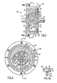
- the apparatus consists of a frame 10 providing a hopper 12 into which the meat and bone mixture to be separated is delivered.
- the hopper contains a longitudinal conveyor screw 14 rotated about a horizontal axis by a drive rotor (not shown) via a connecting drive gear 16 and a splined drive output shaft 18 mounted in a bearing 20 in an end plate of the frame.
- Special bearing seals such as 22 are required, as is well known to those skilled in the art of food handling machinery construction, to prevent entry to the bearings of the body fluids that accompany meats.
- the hopper body is provided with a front end flange 24 to which is fastened the adjacent rear end mounting flange 26 of a rotary, radial-vane, positive-displacement pump indicated generally by the reference 28.
- the pump comprises a cylindrical housing 30 having the rear mounting flange 26 at one end and a comparable front mounting flange 32 at the other end.
- Front and rear bearing plates 34 and 36 respectively are mounted in the cylindrical housing on either side of a hollow cam plate 38, so as to form the pump chamber between them.
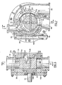
- Both blades are of an axial width to fit without appreciable play between the two facing axial faces of the end bearing plates, and they are both provided with mating complementary half-width radially elongated slots 58a and 58b respectively to permit the required radial sliding movements in the rotor boss as it rotates about the axis 58.
- the tips 60 of the blades engage an internal cam constituted by the inside surface 62 of the bore in the hollow cam plate 38, the tips being rounded to facilitate the rubbing contact as they move over the surface.
- the surface 62 is generated so that at all times during the rotation of the pump rotor the blade tips are in contact with it, so that the contents of the pump chamber are positively displaced through the pump from the inlet to the outlet, and relatively high pump pressures, e.g. usually from 70-210 Kg/sq. cm (1000-3000 p.s.i.), can readily be generated.
- relatively high pump pressures e.g. usually from 70-210 Kg/sq. cm (1000-3000 p.s.i.
- the chamber encloses an elongated feed screw 84 mounted by splined front rotor end 46 and a bearing 86 for rotation about an axis coaxial with the pump axis 58, and driven in such rotation by the rotor end 46.
- Rotation of the screw 84 conveys the pump-pressurised mixture of meat and bone along the interior of the cylindrical separation chamber 70, the pressure being such that the softer meat is squeezed through the separator screen 76 to the outside (i.e. downstream) separator surface, constituting in this embodiment the meat fraction outlet, from which it will fall into a suitable collector receptacle (not shown), while the bone and unseparated meat eventually exit from an annular bone fraction outlet 88 to another respective collector receptacle (also not shown).
- a suitable collector receptacle not shown
- the bone and unseparated meat eventually exit from an annular bone fraction outlet 88 to another respective collector receptacle (also not shown).
- the maximum arc shall be of constant radius R, and this is the arc ACB at 128 with chord equal to the blade length L. Some correction must be made to L to account for the width of the blade and for the rounded tips of radius W/2.
- the variable cam radius r measured from centre 128 will vary with the angle 6 and can be calculated geometrically, but an exact equation solution is not easily attainable. The problem is particularly suited to an iterative approach, especially with the use of a computer to effect the relative large number of calculations required to obtain the values of the cam radius necessary for the required accuracy of manufacture.
Landscapes
- Life Sciences & Earth Sciences (AREA)
- Engineering & Computer Science (AREA)
- Wood Science & Technology (AREA)
- Zoology (AREA)
- Food Science & Technology (AREA)
- Rotary Pumps (AREA)
- Meat, Egg Or Seafood Products (AREA)
- Processing Of Solid Wastes (AREA)
- Filtration Of Liquid (AREA)
- Structures Of Non-Positive Displacement Pumps (AREA)
- Processing Of Meat And Fish (AREA)
- Extraction Or Liquid Replacement (AREA)
Claims (13)


Priority Applications (1)
| Application Number | Priority Date | Filing Date | Title |
|---|---|---|---|
| AT84304586T ATE30830T1 (de) | 1983-07-13 | 1984-07-04 | Geraet zum trennen eines gemisches von mehrphasigen materialien wie fleisch und knochen. |
Applications Claiming Priority (2)
| Application Number | Priority Date | Filing Date | Title |
|---|---|---|---|
| US51348783A | 1983-07-13 | 1983-07-13 | |
| US513487 | 1983-07-13 |
Publications (3)
| Publication Number | Publication Date |
|---|---|
| EP0132084A2 EP0132084A2 (de) | 1985-01-23 |
| EP0132084A3 EP0132084A3 (en) | 1985-07-03 |
| EP0132084B1 true EP0132084B1 (de) | 1987-11-19 |
Family
ID=24043496
Family Applications (1)
| Application Number | Title | Priority Date | Filing Date |
|---|---|---|---|
| EP84304586A Expired EP0132084B1 (de) | 1983-07-13 | 1984-07-04 | Gerät zum Trennen eines Gemisches von mehrphasigen Materialien wie Fleisch und Knochen |
Country Status (6)
| Country | Link |
|---|---|
| EP (1) | EP0132084B1 (de) |
| JP (1) | JPH0692039B2 (de) |
| AT (1) | ATE30830T1 (de) |
| BR (1) | BR8403482A (de) |
| CA (1) | CA1231581A (de) |
| DE (2) | DE132084T1 (de) |
Cited By (1)
| Publication number | Priority date | Publication date | Assignee | Title |
|---|---|---|---|---|
| EP0700639A1 (de) | 1994-09-12 | 1996-03-13 | Les Innovations Mecaniques Alimentaires | Vorrichtung zum mechanischem Trennen eines Gemisches von Fleisch und harter Elemente |
Families Citing this family (8)
| Publication number | Priority date | Publication date | Assignee | Title |
|---|---|---|---|---|
| FR2565851B1 (fr) * | 1984-06-14 | 1994-02-11 | Innovations Meca Alimentaires | Tete de separation mecanique destinee notamment au traitement des carcasses broyees et machine qui en est equipee |
| US5813909A (en) * | 1996-01-23 | 1998-09-29 | Beehive, Inc. | Deboning machine with slotted separation chamber |
| US5667435A (en) * | 1996-04-16 | 1997-09-16 | Beehive, Inc. | Method and apparatus for separating meat from bones |
| CN103231539B (zh) * | 2013-04-11 | 2015-06-10 | 深圳市鲜油宝健康科技有限公司 | 轴腔进料的家用榨油机螺旋轴及榨油机和检测控制方法 |
| JP6345149B2 (ja) * | 2015-04-06 | 2018-06-20 | 株式会社杉原工業 | スクリュー脱液機 |
| DE102016104224B4 (de) * | 2016-03-08 | 2017-11-23 | Mado Gmbh | Vorrichtung zum Abscheren von Fleisch von Knochen |
| CN108157473A (zh) * | 2017-12-28 | 2018-06-15 | 锦岸机械科技江苏有限公司 | 一种双方向肉骨粉碎输出机构 |
| JP7043722B2 (ja) * | 2020-06-22 | 2022-03-30 | 株式会社Tatsコーポレーション | 骨肉分離装置 |
Family Cites Families (4)
| Publication number | Priority date | Publication date | Assignee | Title |
|---|---|---|---|---|
| DE54866C (de) * | G. BÄUER-LEIN-GERMANN in Zürich-Unterstrafs, Beckenhofstrafse 37 | Wurststopfmaschine | ||
| US2895162A (en) * | 1957-11-08 | 1959-07-21 | Blue Channel Corp | Machine for recovering meat from animal carcasses |
| FR1460403A (fr) * | 1965-12-20 | 1966-11-25 | Vtoroi Kolbasny Zd | Machine poussoir à fabriquer en continu les saucissons |
| US4340184A (en) * | 1979-12-03 | 1982-07-20 | Poss Design Limited | Apparatus for mechanical separation of a combination of meat and bone into useful fractions |
-
1984
- 1984-06-28 CA CA000457802A patent/CA1231581A/en not_active Expired
- 1984-07-04 DE DE198484304586T patent/DE132084T1/de active Pending
- 1984-07-04 EP EP84304586A patent/EP0132084B1/de not_active Expired
- 1984-07-04 AT AT84304586T patent/ATE30830T1/de not_active IP Right Cessation
- 1984-07-04 DE DE8484304586T patent/DE3467495D1/de not_active Expired
- 1984-07-12 BR BR8403482A patent/BR8403482A/pt not_active IP Right Cessation
- 1984-07-13 JP JP59144545A patent/JPH0692039B2/ja not_active Expired - Lifetime
Cited By (1)
| Publication number | Priority date | Publication date | Assignee | Title |
|---|---|---|---|---|
| EP0700639A1 (de) | 1994-09-12 | 1996-03-13 | Les Innovations Mecaniques Alimentaires | Vorrichtung zum mechanischem Trennen eines Gemisches von Fleisch und harter Elemente |
Also Published As
| Publication number | Publication date |
|---|---|
| JPS6040697A (ja) | 1985-03-04 |
| DE132084T1 (de) | 1987-02-26 |
| JPH0692039B2 (ja) | 1994-11-16 |
| DE3467495D1 (en) | 1987-12-23 |
| ATE30830T1 (de) | 1987-12-15 |
| BR8403482A (pt) | 1985-06-25 |
| EP0132084A2 (de) | 1985-01-23 |
| EP0132084A3 (en) | 1985-07-03 |
| CA1231581A (en) | 1988-01-19 |
Similar Documents
| Publication | Publication Date | Title |
|---|---|---|
| US4638954A (en) | Apparatus for the separation of mixtures of materials of different consistencies such as meat and bone | |
| CA1062539A (en) | Process and apparatus for the mechanical separation of a combination of meats and bone | |
| EP0132084B1 (de) | Gerät zum Trennen eines Gemisches von mehrphasigen Materialien wie Fleisch und Knochen | |
| CA1154999A (en) | Process and apparatus for mechanical separation of a combination of meat and bone into useful fractions | |
| USRE33752E (en) | Apparatus for the separation of mixtures of materials of different consistencies such as meat and bone | |
| HU206030B (en) | Device for feeding-in triturating machines | |
| US4153208A (en) | Mincing machine for grinding up food | |
| US4205415A (en) | Food product extrusion apparatus | |
| US5906297A (en) | Multi-outlet depositor | |
| EP0134636B1 (de) | Drehschieberpumpen | |
| EP1247984B1 (de) | Schneckenfördereinrichtung für Flüssigkeiten und/oder Materialbrocken | |
| US20160051990A1 (en) | Mincing machine for mincing a product | |
| US3906118A (en) | Process for de-boning meat or fish | |
| KR20160113629A (ko) | 그라인더 조립체 | |
| US3659638A (en) | Heavy duty machine for production of comminuted meat and other foods | |
| FI72895B (fi) | Foerfarande och anordning foer disintegrering av material. | |
| GB2292880A (en) | Size reduction of cuttable materials | |
| AU2020347559B2 (en) | Shredding drum for a cutting and separating device | |
| US4077089A (en) | Process and apparatus for meat deboning | |
| DE19948493C2 (de) | Förder-, Pump- und Schneidsystem für Lebensmittelzerkleinerungsmaschinen, insbesondere für Fleischwölfe | |
| US11570997B2 (en) | Conveying screw for a cutting and separating device | |
| GB1318742A (en) | Process and apparatus for producing de-boned meat products | |
| CN212629714U (zh) | 肉制品加工用切割搅拌装置 | |
| EP4403035A1 (de) | Vorrichtung und verfahren zum trennen von fleisch von knochen | |
| US20250282555A1 (en) | Conveyor device and filling machine for pasty foods |
Legal Events
| Date | Code | Title | Description |
|---|---|---|---|
| PUAI | Public reference made under article 153(3) epc to a published international application that has entered the european phase |
Free format text: ORIGINAL CODE: 0009012 |
|
| AK | Designated contracting states |
Designated state(s): AT BE DE FR GB IT NL |
|
| PUAL | Search report despatched |
Free format text: ORIGINAL CODE: 0009013 |
|
| AK | Designated contracting states |
Designated state(s): AT BE DE FR GB IT NL |
|
| 17P | Request for examination filed |
Effective date: 19851216 |
|
| ITCL | It: translation for ep claims filed |
Representative=s name: ING. C. GREGORJ S.P.A. |
|
| TCNL | Nl: translation of patent claims filed | ||
| TCAT | At: translation of patent claims filed | ||
| 17Q | First examination report despatched |
Effective date: 19861030 |
|
| EL | Fr: translation of claims filed | ||
| DET | De: translation of patent claims | ||
| RAP1 | Party data changed (applicant data changed or rights of an application transferred) |
Owner name: POSS DESIGN LIMITED |
|
| GRAA | (expected) grant |
Free format text: ORIGINAL CODE: 0009210 |
|
| AK | Designated contracting states |
Kind code of ref document: B1 Designated state(s): AT BE DE FR GB IT NL |
|
| REF | Corresponds to: |
Ref document number: 30830 Country of ref document: AT Date of ref document: 19871215 Kind code of ref document: T |
|
| ITF | It: translation for a ep patent filed | ||
| REF | Corresponds to: |
Ref document number: 3467495 Country of ref document: DE Date of ref document: 19871223 |
|
| ET | Fr: translation filed | ||
| PLBE | No opposition filed within time limit |
Free format text: ORIGINAL CODE: 0009261 |
|
| STAA | Information on the status of an ep patent application or granted ep patent |
Free format text: STATUS: NO OPPOSITION FILED WITHIN TIME LIMIT |
|
| 26N | No opposition filed | ||
| ITTA | It: last paid annual fee | ||
| PGFP | Annual fee paid to national office [announced via postgrant information from national office to epo] |
Ref country code: GB Payment date: 19980625 Year of fee payment: 15 |
|
| PGFP | Annual fee paid to national office [announced via postgrant information from national office to epo] |
Ref country code: FR Payment date: 19980709 Year of fee payment: 15 |
|
| PGFP | Annual fee paid to national office [announced via postgrant information from national office to epo] |
Ref country code: DE Payment date: 19980713 Year of fee payment: 15 Ref country code: AT Payment date: 19980713 Year of fee payment: 15 |
|
| PGFP | Annual fee paid to national office [announced via postgrant information from national office to epo] |
Ref country code: NL Payment date: 19980728 Year of fee payment: 15 |
|
| PGFP | Annual fee paid to national office [announced via postgrant information from national office to epo] |
Ref country code: BE Payment date: 19980914 Year of fee payment: 15 |
|
| PG25 | Lapsed in a contracting state [announced via postgrant information from national office to epo] |
Ref country code: GB Free format text: LAPSE BECAUSE OF NON-PAYMENT OF DUE FEES Effective date: 19990704 Ref country code: AT Free format text: LAPSE BECAUSE OF NON-PAYMENT OF DUE FEES Effective date: 19990704 |
|
| PG25 | Lapsed in a contracting state [announced via postgrant information from national office to epo] |
Ref country code: FR Free format text: THE PATENT HAS BEEN ANNULLED BY A DECISION OF A NATIONAL AUTHORITY Effective date: 19990731 Ref country code: BE Free format text: LAPSE BECAUSE OF NON-PAYMENT OF DUE FEES Effective date: 19990731 |
|
| BERE | Be: lapsed |
Owner name: POSS DESIGN LTD Effective date: 19990731 |
|
| PG25 | Lapsed in a contracting state [announced via postgrant information from national office to epo] |
Ref country code: NL Free format text: LAPSE BECAUSE OF NON-PAYMENT OF DUE FEES Effective date: 20000201 |
|
| GBPC | Gb: european patent ceased through non-payment of renewal fee |
Effective date: 19990704 |
|
| NLV4 | Nl: lapsed or anulled due to non-payment of the annual fee |
Effective date: 20000201 |
|
| PG25 | Lapsed in a contracting state [announced via postgrant information from national office to epo] |
Ref country code: DE Free format text: LAPSE BECAUSE OF NON-PAYMENT OF DUE FEES Effective date: 20000503 |
|
| REG | Reference to a national code |
Ref country code: FR Ref legal event code: ST |