EP0132253A2 - Serrure cylindrique - Google Patents
Serrure cylindrique Download PDFInfo
- Publication number
- EP0132253A2 EP0132253A2 EP84890131A EP84890131A EP0132253A2 EP 0132253 A2 EP0132253 A2 EP 0132253A2 EP 84890131 A EP84890131 A EP 84890131A EP 84890131 A EP84890131 A EP 84890131A EP 0132253 A2 EP0132253 A2 EP 0132253A2
- Authority
- EP
- European Patent Office
- Prior art keywords
- cylinder
- locking pins
- housing
- locking
- lifters
- Prior art date
- Legal status (The legal status is an assumption and is not a legal conclusion. Google has not performed a legal analysis and makes no representation as to the accuracy of the status listed.)
- Withdrawn
Links
- 230000005484 gravity Effects 0.000 claims abstract description 17
- 238000000034 method Methods 0.000 description 3
- 239000000243 solution Substances 0.000 description 3
- 239000000463 material Substances 0.000 description 2
- 206010001488 Aggression Diseases 0.000 description 1
- 241001136792 Alle Species 0.000 description 1
- 230000004308 accommodation Effects 0.000 description 1
- 239000011324 bead Substances 0.000 description 1
- 230000007423 decrease Effects 0.000 description 1
- 230000000694 effects Effects 0.000 description 1
- 238000003780 insertion Methods 0.000 description 1
- 230000037431 insertion Effects 0.000 description 1
- 238000010008 shearing Methods 0.000 description 1
- 239000012086 standard solution Substances 0.000 description 1
Images

Classifications
-
- E—FIXED CONSTRUCTIONS
- E05—LOCKS; KEYS; WINDOW OR DOOR FITTINGS; SAFES
- E05B—LOCKS; ACCESSORIES THEREFOR; HANDCUFFS
- E05B27/00—Cylinder locks or other locks with tumbler pins or balls that are set by pushing the key in
Definitions
- the invention relates to a cylinder lock with a lock cylinder which is rotatably held in a housing and which is locked by means of locking pins (b1 - b5) held in radial guides, which extend in alignment in the housing and in the cylinder, and by means of levers (y1 - y5) which bear against them a rotation can be secured, whereby by means of a key that can be inserted into an axial opening of the cylinder, the lifters (y1 - y5) and locking pins (b1 - b5) can be brought into a position in which one is completely in the cylinder and the other are entirely in the housing.
- the locking pins are arranged on the underside of the cylinder or engage on the underside thereof.
- the aim of the invention is to avoid these disadvantages and to propose a lock of the type mentioned at the outset, which offers a large number of possible key combinations and is characterized by a high mechanical resistance to a shear test of the locking pins without any particular effort.
- the resistance of the lock according to the invention against an attempt to shear off the locking pins with a tool can be increased in a very simple manner in that a guide of each of the two locking systems is located in a common cross-sectional plane of the cylinder. This means that two lifters would have to be sheared off at the same time, which doubles the resistance of the lock to such shearing off.
- the lock according to the invention differs from the conventional locks of this type only in the area of the cylinder, the remaining part of the lock can remain unchanged, so that it can be installed in the same way as the conventional locks.
- the locking pins (a1-a5) and lifters (x1-x5) which are only loaded by gravity, are held in guides which extend in a vertical plane extending through the axis of the cylinder, thereby causing very simple way the effect of gravity can be fully exploited.
- the height of the jack In order to keep the size of the lock small, the height of the jack must be kept small. This can cause problems with cylindrical jacks when their height decreases to the size of their diameter or less their security against tipping, which can lead to the lock being blocked.
- the lifters (x1 - x5) cooperating with the locking pins (a1 - a5), which are only loaded by gravity, and possibly also the other lifters are designed as balls.
- the diameter of the lifters (x1 - x5) designed as balls is equal to or smaller than the diameter of the locking pins (a1 - a5).
- n ⁇ dx + has> k + t or t + k ⁇ hz + ha) m, where n is the distance of the support of each jack (x1 - x5) from the outside of the cylinder, dx the diameter of the jack (x1 - x5), ha the length of the locking pin (a1 - a5) , t the wall thickness of the housing and k the depth of the guide in the socket of the lock and m definition from A5 and hz the length of the jack (y1 - y5).
- a further feature of the invention provides that circumferential grooves (zpl, zpa) are incorporated into the lateral surface of the cylinder, into which plates (p1, p2) held in the housing engage.
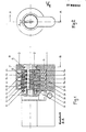
- FIG. 1 shows a partial section through a lock according to the invention of a first embodiment without a key inserted
- FIG. 2 shows a front view of the lock according to FIG. 1
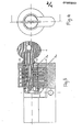
- FIGS. 3 and 4 shows the lock according to FIGS. 1 and 2 with a key inserted
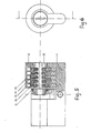
- FIG. 5 6 shows a partial section and front view of a further embodiment of a lock according to the invention
- FIGS. 7 and 8 show details of FIGS. 1 and 5 on an enlarged scale
- FIG. 9 shows a cross section through the lock according to FIGS. 1 to 4.
- the two locking systems of the cylinder locks according to the invention can be seen in the longitudinal sectional view.
- the cylinder 2 is provided with locking pins - a5, which form one of the locking systems with the lifters x1 - x5, while on the underside there is a standard system with locking pins b1 - b5 and lifters y1 - y5, which are pretensioned by springs .
- the other part of the lock in Fig. 1 - to the left of the axis of symmetry - shows a standard solution with one-sided locking system of the cylinder by means of locking pins and cylindrical jacks under the action of springs. As can be seen from FIGS.
- the locking pins a1-a5 of the locking system arranged in the upper area of the cylinder 2 or housing 1 are only loaded against the cylinder 2 by gravity.
- the cylinder lock is based on a uniform principle, according to which the locking pins are in a position in which they are located with one part in the cylinder 2 and the other in the housing 1 and the socket 3 of the lock, as long as no key is inserted.
- shut-off pins a1-a5 and the jacks x1-x5 are chosen so that it is impossible to use them simultaneously and completely in cylinder 2 to accommodate and also that they can not be pushed out of the cylinder at the same time and completely, that is, place in the housing 1 and in the socket 3 of the lock, which can be mathematically expressed by the following inequalities: n ⁇ d x + h a > k + t according to Fig. 7 m ⁇ h z + h a > k + t according to Fig. 5
- n is the distance of the support of each jack (x1 - x5) from the outside of the cylinder, dx the diameter of the jack (x1 - x5), ha the length of the locking pin (a1 - a5), t the wall thickness of the housing and k the Depth of the guide in the socket of the lock and m definition from A5 and hz the length of the jack (y1 - y5).
- beads are used as lifters for the locking pins, as a result of which stability problems are avoided at low heights.
- Ball lifters have a significant advantage over cylindrical lifters, in cases where lifters of smaller dimensions or heights are necessary, i.e. if h ⁇ d, where h is the height of the lifter and d is the diameter of the assigned locking pin or its guide, because cylindrical lifters tend to fall over with small dimensions and thereby make the functioning of the lock unsafe.
- h the height of the lifter
- d the diameter of the assigned locking pin or its guide
Landscapes
- Automatic Assembly (AREA)
- Lock And Its Accessories (AREA)
Applications Claiming Priority (2)
| Application Number | Priority Date | Filing Date | Title |
|---|---|---|---|
| YU1501/83 | 1983-07-12 | ||
| YU150183A YU45139B (en) | 1983-07-12 | 1983-07-12 | Cylindrical lock with double cylinder locking |
Publications (2)
| Publication Number | Publication Date |
|---|---|
| EP0132253A2 true EP0132253A2 (fr) | 1985-01-23 |
| EP0132253A3 EP0132253A3 (fr) | 1985-10-02 |
Family
ID=25554402
Family Applications (1)
| Application Number | Title | Priority Date | Filing Date |
|---|---|---|---|
| EP84890131A Withdrawn EP0132253A3 (fr) | 1983-07-12 | 1984-07-12 | Serrure cylindrique |
Country Status (2)
| Country | Link |
|---|---|
| EP (1) | EP0132253A3 (fr) |
| YU (1) | YU45139B (fr) |
Family Cites Families (6)
| Publication number | Priority date | Publication date | Assignee | Title |
|---|---|---|---|---|
| DK14164C (da) * | 1911-01-30 | J Lips Bzn | Anordning til Hindring af Udboring af Tilholderne i Yalelaase. | |
| CH188570A (de) * | 1936-02-11 | 1937-01-15 | Diener Heinrich | Sicherheitsschloss mit Stechschlüssel. |
| US2379040A (en) * | 1941-12-13 | 1945-06-26 | Bauer Ag | Pin tumbler lock |
| CH281684A (fr) * | 1949-01-20 | 1952-03-31 | Valiente Oroquieta Jesus | Serrure de sûreté. |
| CH383197A (it) * | 1959-12-18 | 1964-10-15 | Bina Alido | Serratura di sicurezza |
| US3183692A (en) * | 1963-08-28 | 1965-05-18 | Yale & Towne Inc | Construction lock cylinder |
-
1983
- 1983-07-12 YU YU150183A patent/YU45139B/xx unknown
-
1984
- 1984-07-12 EP EP84890131A patent/EP0132253A3/fr not_active Withdrawn
Also Published As
| Publication number | Publication date |
|---|---|
| EP0132253A3 (fr) | 1985-10-02 |
| YU45139B (en) | 1992-03-10 |
| YU150183A (en) | 1986-12-31 |
Similar Documents
| Publication | Publication Date | Title |
|---|---|---|
| DE69005060T2 (de) | Zylinderschloss und Schlüssel. | |
| DE69920530T3 (de) | Schlüssel für ein Zylinderschloss | |
| AT409019B (de) | Flachschlüssel und zylinderschloss | |
| DE2344473B2 (de) | Zylinderkern in einem zylinderschloss mit flachschluessel | |
| DE2412114A1 (de) | Vorrichtung zum verriegeln bestimmter von mehreren herausziehbaren aufbewahrungseinheiten bei einer aufbewahrungseinrichtung, z.b. einem schrank | |
| DE60213791T2 (de) | Behälter für gegenstände | |
| DE2637798B2 (de) | Schlüssel für ein Zylinderschloß | |
| DE102010007675B3 (de) | Schlitzgreifer | |
| DE3111066A1 (de) | Vorhaengeschloss | |
| DE3044294A1 (de) | Zylinderschloss | |
| AT392508B (de) | Flachschluessel und zugehoeriges zylinderschloss | |
| DE102015000213B4 (de) | Schließzylinder mit Plättchenzuhaltungen für ein Zylinderschloss sowie Zylinderschloss mit einem derartigen Schließzylinder | |
| DE963123C (de) | Sicherheitsschloss | |
| EP0059338A1 (fr) | Serrure cylindrique | |
| EP1272720B1 (fr) | Serrure a pompe comportant un boitier cylindrique et cle plate destinee a une serrure a pompe | |
| EP1325995A2 (fr) | Dispositif de sécurité interdisant l'ouverture simultanée, notamment pour armoires à tiroirs | |
| DE69401213T3 (de) | Schlüssel mit zwei abschrägungen am ende für ein sicherheitzylinderschloss und zylinderschloss dafür | |
| DE60224802T2 (de) | Zylinderschlossschlüsselkombination | |
| DE2123850C3 (de) | Flachschlüsselbetätigbares Türschloß | |
| EP0118910A2 (fr) | Cylindre de fermeture | |
| DE868122C (de) | Fallenschloss mit Sperreinrichtung | |
| EP0313733A1 (fr) | Cassette pour emmagasiner des objets oblongs | |
| DE1202222B (de) | Behaelterbefestigungsvorrichtung | |
| AT230762B (de) | Sicherheitsschloß | |
| EP0128475A2 (fr) | Dispositif pour une serrure cylindrique |
Legal Events
| Date | Code | Title | Description |
|---|---|---|---|
| PUAI | Public reference made under article 153(3) epc to a published international application that has entered the european phase |
Free format text: ORIGINAL CODE: 0009012 |
|
| AK | Designated contracting states |
Designated state(s): AT BE CH DE FR GB IT LI LU NL SE |
|
| PUAL | Search report despatched |
Free format text: ORIGINAL CODE: 0009013 |
|
| AK | Designated contracting states |
Designated state(s): AT BE CH DE FR GB IT LI LU NL SE |
|
| STAA | Information on the status of an ep patent application or granted ep patent |
Free format text: STATUS: THE APPLICATION IS DEEMED TO BE WITHDRAWN |
|
| 18D | Application deemed to be withdrawn |
Effective date: 19860603 |