EP0132403A2 - Gerät mit Schrittmotor zur Verwendung bei chirurgisch-implantierbaren Vorrichtungen - Google Patents
Gerät mit Schrittmotor zur Verwendung bei chirurgisch-implantierbaren Vorrichtungen Download PDFInfo
- Publication number
- EP0132403A2 EP0132403A2 EP84304995A EP84304995A EP0132403A2 EP 0132403 A2 EP0132403 A2 EP 0132403A2 EP 84304995 A EP84304995 A EP 84304995A EP 84304995 A EP84304995 A EP 84304995A EP 0132403 A2 EP0132403 A2 EP 0132403A2
- Authority
- EP
- European Patent Office
- Prior art keywords
- aperture
- rotor
- inlet
- magnetic field
- valve seat
- Prior art date
- Legal status (The legal status is an assumption and is not a legal conclusion. Google has not performed a legal analysis and makes no representation as to the accuracy of the status listed.)
- Granted
Links
- 230000005291 magnetic effect Effects 0.000 claims abstract description 76
- 239000000463 material Substances 0.000 claims abstract description 24
- 239000012530 fluid Substances 0.000 claims description 22
- 210000001175 cerebrospinal fluid Anatomy 0.000 claims description 19
- 230000007423 decrease Effects 0.000 claims description 13
- 238000011282 treatment Methods 0.000 claims description 12
- 208000003906 hydrocephalus Diseases 0.000 claims description 11
- 230000004044 response Effects 0.000 claims description 8
- 238000013022 venting Methods 0.000 claims description 8
- 210000001124 body fluid Anatomy 0.000 claims description 7
- 239000010839 body fluid Substances 0.000 claims description 7
- 238000000034 method Methods 0.000 claims description 7
- 230000000694 effects Effects 0.000 claims description 3
- 230000000717 retained effect Effects 0.000 claims description 3
- 230000003247 decreasing effect Effects 0.000 claims 1
- 229910001220 stainless steel Inorganic materials 0.000 description 9
- 239000010935 stainless steel Substances 0.000 description 9
- 230000007246 mechanism Effects 0.000 description 8
- 230000008901 benefit Effects 0.000 description 6
- 230000008859 change Effects 0.000 description 6
- 230000007935 neutral effect Effects 0.000 description 6
- 239000004033 plastic Substances 0.000 description 5
- 229910052594 sapphire Inorganic materials 0.000 description 5
- 239000010980 sapphire Substances 0.000 description 5
- 238000011144 upstream manufacturing Methods 0.000 description 5
- XEEYBQQBJWHFJM-UHFFFAOYSA-N Iron Chemical compound [Fe] XEEYBQQBJWHFJM-UHFFFAOYSA-N 0.000 description 4
- 238000007914 intraventricular administration Methods 0.000 description 4
- 201000003077 normal pressure hydrocephalus Diseases 0.000 description 4
- 230000036961 partial effect Effects 0.000 description 4
- 230000010287 polarization Effects 0.000 description 4
- KPLQYGBQNPPQGA-UHFFFAOYSA-N cobalt samarium Chemical compound [Co].[Sm] KPLQYGBQNPPQGA-UHFFFAOYSA-N 0.000 description 3
- 238000010276 construction Methods 0.000 description 3
- 229940079593 drug Drugs 0.000 description 3
- 239000003814 drug Substances 0.000 description 3
- 230000014759 maintenance of location Effects 0.000 description 3
- 229910000938 samarium–cobalt magnet Inorganic materials 0.000 description 3
- 238000000926 separation method Methods 0.000 description 3
- 239000004695 Polyether sulfone Substances 0.000 description 2
- 210000004556 brain Anatomy 0.000 description 2
- 210000004289 cerebral ventricle Anatomy 0.000 description 2
- 230000007797 corrosion Effects 0.000 description 2
- 238000005260 corrosion Methods 0.000 description 2
- 230000005294 ferromagnetic effect Effects 0.000 description 2
- 210000003128 head Anatomy 0.000 description 2
- 238000002513 implantation Methods 0.000 description 2
- 230000005415 magnetization Effects 0.000 description 2
- BASFCYQUMIYNBI-UHFFFAOYSA-N platinum Chemical compound [Pt] BASFCYQUMIYNBI-UHFFFAOYSA-N 0.000 description 2
- 229920006393 polyether sulfone Polymers 0.000 description 2
- 230000036316 preload Effects 0.000 description 2
- 238000005086 pumping Methods 0.000 description 2
- 210000004761 scalp Anatomy 0.000 description 2
- 208000024891 symptom Diseases 0.000 description 2
- 208000024806 Brain atrophy Diseases 0.000 description 1
- 229920004943 Delrin® Polymers 0.000 description 1
- 229910000640 Fe alloy Inorganic materials 0.000 description 1
- 229910001200 Ferrotitanium Inorganic materials 0.000 description 1
- 206010019233 Headaches Diseases 0.000 description 1
- 229910001182 Mo alloy Inorganic materials 0.000 description 1
- ZOKXTWBITQBERF-UHFFFAOYSA-N Molybdenum Chemical compound [Mo] ZOKXTWBITQBERF-UHFFFAOYSA-N 0.000 description 1
- 229910000990 Ni alloy Inorganic materials 0.000 description 1
- RTAQQCXQSZGOHL-UHFFFAOYSA-N Titanium Chemical compound [Ti] RTAQQCXQSZGOHL-UHFFFAOYSA-N 0.000 description 1
- CLBRCZAHAHECKY-UHFFFAOYSA-N [Co].[Pt] Chemical compound [Co].[Pt] CLBRCZAHAHECKY-UHFFFAOYSA-N 0.000 description 1
- 238000010521 absorption reaction Methods 0.000 description 1
- 230000009471 action Effects 0.000 description 1
- 229910045601 alloy Inorganic materials 0.000 description 1
- 239000000956 alloy Substances 0.000 description 1
- VREFGVBLTWBCJP-UHFFFAOYSA-N alprazolam Chemical compound C12=CC(Cl)=CC=C2N2C(C)=NN=C2CN=C1C1=CC=CC=C1 VREFGVBLTWBCJP-UHFFFAOYSA-N 0.000 description 1
- 238000004458 analytical method Methods 0.000 description 1
- 238000003491 array Methods 0.000 description 1
- 230000004888 barrier function Effects 0.000 description 1
- 239000003990 capacitor Substances 0.000 description 1
- 239000003795 chemical substances by application Substances 0.000 description 1
- 150000001805 chlorine compounds Chemical class 0.000 description 1
- 229910017052 cobalt Inorganic materials 0.000 description 1
- 239000010941 cobalt Substances 0.000 description 1
- GUTLYIVDDKVIGB-UHFFFAOYSA-N cobalt atom Chemical compound [Co] GUTLYIVDDKVIGB-UHFFFAOYSA-N 0.000 description 1
- 238000012790 confirmation Methods 0.000 description 1
- 238000007796 conventional method Methods 0.000 description 1
- 230000001419 dependent effect Effects 0.000 description 1
- 238000011161 development Methods 0.000 description 1
- 231100000869 headache Toxicity 0.000 description 1
- 230000036039 immunity Effects 0.000 description 1
- 230000001771 impaired effect Effects 0.000 description 1
- 238000001802 infusion Methods 0.000 description 1
- 238000011221 initial treatment Methods 0.000 description 1
- 238000002347 injection Methods 0.000 description 1
- 239000007924 injection Substances 0.000 description 1
- 208000014674 injury Diseases 0.000 description 1
- 238000007917 intracranial administration Methods 0.000 description 1
- 229910052742 iron Inorganic materials 0.000 description 1
- 238000004519 manufacturing process Methods 0.000 description 1
- 239000011733 molybdenum Substances 0.000 description 1
- 230000000149 penetrating effect Effects 0.000 description 1
- 230000002093 peripheral effect Effects 0.000 description 1
- 229910052697 platinum Inorganic materials 0.000 description 1
- 230000002829 reductive effect Effects 0.000 description 1
- 230000003252 repetitive effect Effects 0.000 description 1
- 230000000979 retarding effect Effects 0.000 description 1
- 230000002441 reversible effect Effects 0.000 description 1
- 239000010979 ruby Substances 0.000 description 1
- 229910001750 ruby Inorganic materials 0.000 description 1
- 229920002379 silicone rubber Polymers 0.000 description 1
- 239000004945 silicone rubber Substances 0.000 description 1
- 210000003625 skull Anatomy 0.000 description 1
- 229910001256 stainless steel alloy Inorganic materials 0.000 description 1
- 239000010936 titanium Substances 0.000 description 1
- 230000008733 trauma Effects 0.000 description 1
- 230000002861 ventricular Effects 0.000 description 1
Images


Classifications
-
- H—ELECTRICITY
- H02—GENERATION; CONVERSION OR DISTRIBUTION OF ELECTRIC POWER
- H02K—DYNAMO-ELECTRIC MACHINES
- H02K37/00—Motors with rotor rotating step by step and without interrupter or commutator driven by the rotor, e.g. stepping motors
- H02K37/10—Motors with rotor rotating step by step and without interrupter or commutator driven by the rotor, e.g. stepping motors of permanent magnet type
- H02K37/12—Motors with rotor rotating step by step and without interrupter or commutator driven by the rotor, e.g. stepping motors of permanent magnet type with stationary armatures and rotating magnets
- H02K37/14—Motors with rotor rotating step by step and without interrupter or commutator driven by the rotor, e.g. stepping motors of permanent magnet type with stationary armatures and rotating magnets with magnets rotating within the armatures
-
- A—HUMAN NECESSITIES
- A61—MEDICAL OR VETERINARY SCIENCE; HYGIENE
- A61M—DEVICES FOR INTRODUCING MEDIA INTO, OR ONTO, THE BODY; DEVICES FOR TRANSDUCING BODY MEDIA OR FOR TAKING MEDIA FROM THE BODY; DEVICES FOR PRODUCING OR ENDING SLEEP OR STUPOR
- A61M27/00—Drainage appliance for wounds or the like, i.e. wound drains, implanted drains
- A61M27/002—Implant devices for drainage of body fluids from one part of the body to another
- A61M27/006—Cerebrospinal drainage; Accessories therefor, e.g. valves
-
- H—ELECTRICITY
- H02—GENERATION; CONVERSION OR DISTRIBUTION OF ELECTRIC POWER
- H02K—DYNAMO-ELECTRIC MACHINES
- H02K37/00—Motors with rotor rotating step by step and without interrupter or commutator driven by the rotor, e.g. stepping motors
-
- H—ELECTRICITY
- H02—GENERATION; CONVERSION OR DISTRIBUTION OF ELECTRIC POWER
- H02K—DYNAMO-ELECTRIC MACHINES
- H02K7/00—Arrangements for handling mechanical energy structurally associated with dynamo-electric machines, e.g. structural association with mechanical driving motors or auxiliary dynamo-electric machines
- H02K7/06—Means for converting reciprocating motion into rotary motion or vice versa
- H02K7/065—Electromechanical oscillators; Vibrating magnetic drives
-
- A—HUMAN NECESSITIES
- A61—MEDICAL OR VETERINARY SCIENCE; HYGIENE
- A61F—FILTERS IMPLANTABLE INTO BLOOD VESSELS; PROSTHESES; DEVICES PROVIDING PATENCY TO, OR PREVENTING COLLAPSING OF, TUBULAR STRUCTURES OF THE BODY, e.g. STENTS; ORTHOPAEDIC, NURSING OR CONTRACEPTIVE DEVICES; FOMENTATION; TREATMENT OR PROTECTION OF EYES OR EARS; BANDAGES, DRESSINGS OR ABSORBENT PADS; FIRST-AID KITS
- A61F2250/00—Special features of prostheses classified in groups A61F2/00 - A61F2/26 or A61F2/82 or A61F9/00 or A61F11/00 or subgroups thereof
- A61F2250/0001—Means for transferring electromagnetic energy to implants
Definitions
- This invention relates, in one aspect,to surgically- implanted devices, e.g., shunt valves for venting cerebrospinal fluid ("CSF") in the treatment of hydrocephalus and similar conditions of impaired circulation and absorption of body fluids.
- CSF cerebrospinal fluid
- the invention also relates in another aspect to stepping motors which may be adapted so as to find a use in such devices.
- Cerebrospinal fluid shunt valves have been in use for over twenty years. Broadly speaking, they function by venting excess cerebrospinal fluid from the brain into the venous system or other receptive cavities (e.g., peritoneal, pleural). Many such valves, including the earliest designs, operate by controlling the amount of fluid flow. The neurosurgeon makes an estimate of the amount of flow required to relieve the hydrocephalus and selects a valve of that flow capacity. The selection is made difficult by the wide variation in normal flow rates.
- the pressure difference across the valve e.g., the pressure difference between the cerebral ventricle and the drainage site
- the ball rises from the seat to vent cerebrospinal fluid.
- the ball moves further away from the seat to provide a larger valve orifice, one that is always large enough that the pressure drop across the orifice never rises much above the popping pressure. Accordingly, the differential pressure across the valve remains nearly constant for any flow rate encountered within the cerebrospinal fluid system.
- the Cordis-Hakim valve As successful as the Cordis-Hakim valve has been, it has one important limitation. It can only provide a fixed popping pressure. In treating hydrocephalus, it is often desirable to vary the popping pressure in accordance with ventricle size and treatment objective. For example, initial treatment may require a lower than normal pressure to initiate shrinkage of the ventricles, but as the ventricles decrease in size, the popping pressure should be increased gradually so that when the ventricles return to normal size the intraventricular pressure is at its normal value and the intracranial force systems are in balance (i.e., the popping pressure is set at a level that will stabilize the ventricles at a desired size). Generally speaking, the popping pressure should be varied inversely with the ventricle size.
- a further reason for providing adjustablility in popping pressure is to correct for the wide variation in nominal popping pressure typical in manufactured valves.
- the popping pressure can be more accurately set at the factory, and can be checked, and corrected if necessary, in the operating room prior to implantation.
- Implantable magnetically-driven devices have been proposed.
- Levy et al. U.S. Patent No. 4,360,007 discloses an implantable actuator with a ratchet wheel, pawl, and permanent magnet; application of an external magnetic field rotates the implanted magnet and pawl to advance the ratchet wheel.
- Stepping motors have been known per se for many years.
- the simplest stepping motor consists of a permanent magnet rotor surrounded by a stator made up of four electromagnets. By selectively energizing the electromagnets, it is possible to turn the rotor in angular "steps" of 90°. Often the rotor has a plurality of permanent magnets, so as to reduce the angular step size.
- Some stepping motors replace the permanent magnets on the rotor with regions of different magnetic reluctance; in these, known as variable reluctance motors, the rotor turns to the position of minimum reluctance.
- Still others, known as hybrids combine reluctance differences with permanent magnets.
- Stepping motors have been used in some medical applications. For example, they have been used in medical infusion pumps for delivering precise volumetric dosages of drugs at prescribed time intervals. In all these applications the stepping motor was located outside the patient's body, either in a portable device carried by the patient or in a bedside unit.
- pacemakers Other types of medical devices (e.g., pacemakers) have been implanted in the body. These have typically relied for a power source on batteries implanted along with the device.
- a stepping motor isolated physically from electrical power sources and adapted to be powered by the influence of a magnetic field applied from outside the apparatus, said stepping motor comprising a rotor and one or more stator elements, said stator elements being composed of magnetically soft and permeable material shaped and positioned with respect to said rotor so that when magnetized under the influence of said external field the said stator elements strengthen and orient the magnetic field in their vicinities so as to cause movement of said rotor.
- the stepping motor may be installed in a surgically- implanted device and operated by application of a magnetic field applied from outside the body.
- the stepping motor may be operated while totally isolated physically from any source of electrical power (i.e.,without batteries and without wire connections to an external power source).
- the usual electromagnets used for the stator are replaced by pieces of magnetically soft and permeable material (e.g., pure iron or special alloys such as vacoperm).
- the externally applied magnetic field is used to magnetize the stator elements so that the localized magnetic field in the vicinity of the stator elements causes rotation of the rotor.
- the external magnetic field need not be applied with great precision, as the stator elements strengthen and orient the effect of the magnetic field in their vicinities.
- the rotor has a plurality of permanently magnetic poles; there are a plurality of stator elements spaced around the rotor or one stator element with a plurality of lobes so spaced; the external magnetic field is applied using apparatus having a plurality of electromagnets, which are equal in number to the stator elements (or lobes of one element) and positioned similarly; and the stator elements are composed either of soft and permeable material or of such material wrapped by an electrical coil (in which is induced an electrical current, which in turn helps magnetize the soft, permeable stator material).
- apparatus in accordance with the first aspect of this invention and including the stepping motor is not necessarily restricted to being surgically implantable.
- the invention has the advantage of allowing a mechanical movement (e.g., rotary or linear) to be induced within an implanted device (e.g., to alter the pressure setting of a valve, to activate a switch, or to vary the parameter of an electrical circuit) without any physical connection (e.g., electrical wires) with the device. It makes possible implanting a device with an internal element whose position can be accurately adjusted without the need for any wires, tubes, or other physical elements penetrating through the skin, or the use of implanted batteries. Possible applications include cerebrospinal fluid shunt valves (wherein the working pressure may be noninvasively adjusted very precisely) and implantable pumps for precise volumetric delivery of drugs.
- a mechanical movement e.g., rotary or linear
- an implanted device e.g., to alter the pressure setting of a valve, to activate a switch, or to vary the parameter of an electrical circuit
- any physical connection e.g., electrical wires
- the invention features a surgically-implantable shunt valve in which the popping pressure is adjusted in finite increments by application of an external magnetic field.
- the magnetic field causes rotation of a member, which, in turn, moves a portion of the spring biasing the ball against the valve seat; each pulse or cycle of the magnetic field causes one incremental change in the popping pressure (e.g., ten or more cycles are required to move from minimum to maximum pressure); a toothed gear is moved by a rotating escapement element, which is driven by the magnetic field; the gear is connected to a screw or cam that, in turn, changes the bias setting of the spring; in some embodiments, a ferromagnetic element or permanent magnet is mounted on an arm extending radially from said escapement element, a spring is provided to return the arm and escapement to a neutral position, and application of a single external magnetic pulse causes the arm and escapement to move away from and then back to the neutral position sufficiently to cause an incremental rotation of the gear; in other embodiments, two escapement
- a three-arm spring is used in conjunction with magnetic adjustment.
- the spring has two flanking arms retained at their ends and a central arm that biases the ball of the valve.at one end and is moved in response to the magnetic adjustment at the other end.
- a yoke retains such a three-arm spring.
- the yoke extends alongside the inner edges of the flanking arms ( to provide sideward retention for the spring) and over the top surface of those arms (to provide upward retention); the yoke is U-shaped to pass under the central arm and upwardly between the central and flanking arms; and notches are provided in flanking arms to receive portions of the yoke (to provide longitudinal retention).
- the invention in its second aspect has the advantages of immunity to the magnetic field generated by NMR (nuclear ' magnetic resonance) diagnostic devices; such devices generate a steady magnet field, which cannot cause more than about one incremental change of popping pressure. It is also resistant to other incidental magnetic fields because repetitive, strong magnetic pulses are required to cause a substantial adjustment to popping pressure.
- the invention provides a simple, reliable and accurate technique for noninvasive adjustment of popping pressure.
- a shunt valve assembly 10 with two shunt valves 12, 14 separated by a pumping chamber 16.
- Cerebroventricular catheter 18 is connected to the inlet of the valve assembly, and drainage catheter 20, to the outlet.
- This assembly can be surgically implanted following well-known procedures.
- Valve body 22 (a surgically implantable material such as polyethersulfone or stainless steel) has within its interior an inclined plate 24 (stainless steel) held in place by molded portions 25 (plastic molded in place using forms inserted within the valve and subsequently removed).
- inclined plate 24 formed in plate 24 is a circular aperture 26, the periphery of which forms a valve seat for spherical ball 28 (highly-polished sapphire). The periphery has a coined, beveled edge.
- spring 30 Biasing the ball against the valve seat is spring 30 (single piece of stainless steel), which is shown in plan view in Fig. 4.
- the spring has central arm 32 with enlarged end 34 with dimple 35 overlying and capturing ball 28.
- the central arm is joined to two flanking arms 36, 38 at a rear portion 40, in which there is provided hole 42 for receiving the threaded end of shaft 44.
- Shaft 44 is supported at one end in a hole formed in plate 24, and at the other end in a hole formed in upper, integral extension 45 of plate 24.
- Fixed to the shaft at the end opposite the spring is toothed gear 46.
- Freely mounted to the shaft above the gear is magnetic adjustment arm 48, consisting of base 50 (stainless steel) mounted to the shaft, extension arm 52 (which extends from the base and has a step shape to pass around gear 46), and ferro-magnetic element 54 (or permanent magnet).
- Torsion spring 56 (stainless steel) with portions 58 flanking each side of base 50 serves to urge the arm 48 back to its equilibrium position (shown in dashed lines in Fig. 3).
- the torsion spring is mounted around stub shaft 57, which is secured to plate extension 45.
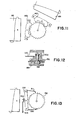
- FIGs. 6-10 there is shown a second preferred embodiment of the invention.
- Assembly 100 shown in the figures would replace downstream valve 14 shown in Figs. 1-5.
- a tubular plastic covering would be fitted tightly around the exterior of the assembly.
- a similar assembly, but absent the adjustment means, would replace upstream valve 12.
- Upper and lower housings 102, 104 are ultrasonically welded together so as to clamp therebetween plate 106 (stainless steel).
- Circular aperture 108 in plate 106 provides a valve seat for spherical ball 110 (highly-polished sapphire).
- 0-ring 112 installed in groove 113 in lower housing 104 provides a seal between the lower housing and the plate in the vicinity of the valve seat, to ensure that all flow through the valve is through the orifice formed between ball 110 and the valve seat 108.
- Cavity 114 in lower housing 104 provides the flow path for fluid upstream of. the valve seat.
- Ball 110 is biased against the valve seat by spring 116, which is shown in plan view in Fig. 6, and which has a central arm 120, extending from above the ball to an adjustment screw 118 at the other end of the assembly, and two flanking arms 122, the ends of which are held beneath the arms 124 of yoke 126, which is U-shaped at its upper end so as to pass around central arm 120, and which is an integral extension of plate 106 (all of which is shown most clearly in Fig. 8).
- Notches 123 cut in the ends of flanking arms 122 (Fig. 8a) receive the yoke arms 124, and secure the spring against longitudinal movement.
- the spring is secured against sideward movement by contact with the vertical outside surfaces of yoke 126.
- Spring arm 120 is received in slot 128 in the head of screw 118, and rests on a wedge-shaped protrusion 130 within the slot. In that way, the screw is prevented from turning, and the force applied to the spring by the screw is transferred in a vertical direction at the center of the spring arm.
- the height of screw 118, and thus the amount of force applied to the spring, is adjusted by turning gear 132, which is threaded to screw 118.
- Gear 132 has integral shaft 134 extending into lower housing 104. Screw 118 is threaded into the interior of integral shaft 134.
- Gear 132 which has 14 teeth, is rotated by movement of escapement elements 136, 138 (best shown in Fig. 9).
- the escapement elements which are mirror images of one another, are keyed to permanent magnets 140, 142, and each escapement-magnet pair is supported for free rotation on a shaft 144 supported in lower housing 104.
- the escapement elements are prevented from falling out of the lower housing by protrusions 146 (Fig. 7), which extend down over the heads of the shafts from upper housing 102.
- the centers of rotation of the escapement elements are positioned along radial lines Rl and R 2 , which are separated by an angle corresponding to a whole number of teeth plus one half of a tooth of gear 132 (the number of integral teeth can be varied, but it is preferred that there remain an additional one-half tooth separation).
- Both magnets 140, 142 are oriented so that their north-south axes have the same polarity and are parallel when the escapement teeth are positioned relative to the gear teeth as shown in Fig. 9.
- FIGs. 17-32 there is shown another embodiment of the invention.
- a shunt valve assembly 310 with two shunt valves 312, 314 separated by a pumping chamber 316.
- Cerebroventricular catheter 318 is connected to the inlet of the valve assembly, and drainage catheter 320, to the outlet.
- This assembly can be surgically implanted following well-known procedures.
- Valve body 322 injection molded from a surgically-implantable material such as polyethersulfone
- the plate 324 has circular aperture 326 in which is press fit a sapphire ring 328, with frustoconical surface 330 forming a valve seat for spherical ball 332 (highly-polished ruby).
- Biasing the ball against the valve seat is spring 334 (single piece of stainless steel or another suitable material), shown in plan view in Fig. 19.
- the spring provides a low K factor to produce little change in working pressure with changes in flow (i.e., a flat flow-pressure curve).
- the spring has base 336 overlying ball 332, central arm 338 extending from the base to an adjustment mechanism, and two flanking arms 340, 342 extending from the base to a yoke 344.
- the yoke is press fit into a hole in plate 324 and tabs 346 extend over the tops of the flanking arms.
- the yoke is relieved in the center to provide room for the central arm to pass through.
- Notches (not shown) cut in the ends of flanking arms 340, 342 receive portions of the yoke, and secure the spring against longitudinal movement.
- the spring is secured against sideward movement by contact of the flanking arms with the vertical outside surfaces of the yoke.
- Plate 324 is held tightly in place within valve body 322.
- the tight fit is achieved by sliding the plate into the valve body (in a direction from right to left in Fig. 18).
- Grooves 354, 356 at the upstream end of the valve body receive portions 350, 352 (Fig. 24) of the plate, and grooves 349 at the downstream end receive tabs 348 on the plate.
- the grooves extend generally horizontally rather than in the inclined direction followed by the plate, and thus the tabs 348 and portions 350, 352 tend to become tightly wedged into the grooves.
- Grooves 354, 356 at the ball end of the valve body also serve to press plate 324 downwardly so as to squeeze it tightly against 0-ring 358 (silicone rubber), which provides an internal seal to ensure that all flow through the valve is through the orifice formed between the ball 332 and the valve seat 330. Flow through the valve is from inlet cavity 360, past ball 332, and into outlet cavity 362.
- 0-ring 358 silicone rubber
- the preload of spring 334 against ball 332 is adjusted by using cam 366 (Delrin) to vary the vertical position (through a 0.75 mm range) of free end 364 of central arm 338.
- the spring preload establishes the pressure of the valve.
- the cam (best shown in Figs. 21-23) has a circular staircase of eighteen steps, each being grooved so as to have a V-shape cross section.
- Free end 364 of arm 338 has a similar V-shape chosen to mate with the V-shape of steps 368.
- a barrier is provided by element 370. This confines rotation of the cam to slightly less than one revolution.
- steps 368 act as detents to keep the cam in precisely one of eighteen possible angular positions. That means that the vertical position of free end 364 of arm 338 is always at precisely one of eighteen different values and, in turn, that the working pressure of the valve is always at one of eighteen possible levels.
- Cam 366 is press fit into the central hole in rotor 372 (4 mm diameter), with a protrusion on the cam fitting into recess 373 in the rotor to assure accurate angular positioning.
- the cam-rotor unit rotates loosely on shaft 376, the base of which is press fit into plate 324. The unit is retained by retaining element 377 secured to the top of the shaft.
- the rotor is preferably made of platinum cobalt or samarium cobalt (which may be plated with platinum to improve corrosion resistance).
- the rotor has ten permanently magnetic poles 374 of alternate polarity (Figs. 25-26). At any one angular position, the pole exposed on the top surface of the disk is opposite that of the one exposed on the bottom surface.
- stator elements 378 each made of a material that is magnetically soft and permeable, and that is resistant to corrosion in the presence of cerebrospinal fluid, which contains chlorides. Preferred materials include magnetic stainless steel alloys and alloys of nickel, iron, and molybdenum or cobalt.
- the stator elements are embedded in a plastic member 380, which is fixed to plate 324 by means of shaft 376.
- the stator elements are shaped so that the portion of each lying beneath the rotor matches the size of permanent magnets 374.
- the portions of the stator elements lying radially beyond the rotor are sized to match the area beneath the rotor so that the boundary between poles, when the stator is magnetized, is at the perimeter of the rotor.
- the shunt valve assembly is surgically implanted in a patient following well-known procedures.
- the pressure of adjustable valve 314 can be set to the desired level according to the circumstances of the case. For instance, it can be set approximately equal to the patient's pre-operative ventricular CSF pressure so that no immediate pressure change occurs as a result of the operation.
- the pressure is adjusted downwardly to the desired level.
- the pressure is lowered to a level sufficient to initiate shrinkage of the cerebral ventricle. Further adjustments in pressure can be made at subsequent times, as necessary.
- the pressure would be adjusted upwardly after sufficient shrinkage of the ventricle has occurred in order to stabilize ventricle size.
- the pressure should be lowered to a level inversely proportional to the ventricle size to reduce stress on the brain parenchyma (see Fig. 13 of Hakim et al., "The Physics of the Cranial Cavity", Surg. Neurol., Vol. 5, March 1976), and as the ventricle decreases in size the pressure of the valve should be increased, so when the ventricle attains normal size the intraventricular pressure is again normal, thereby avoiding development in the patient of a slit-ventricle condition. Also in cases of normal-pressure hydrocephalus, sometimes in spite of a low-pressure valve the patient does not improve and the ventricle size remains unchanged, making the surgeon think he is dealing with a case of brain atrophy.
- Another advantage of the invention arises in the procedure for determining when an implanted shunt valve can safely be removed from a patient, i.e., determining whether the patient is still dependent on the valve for drainage of excess cerebrospinal fluid.
- the conventional technique for making that determination has been to temporarily pinch closed the tube downstream of the valve and observe the patient for symptoms (e.g., slight headache) indicative of valve dependency. In the absence of symptoms the valve can be removed. With the invention it is unnecessary to stop flow entirely. A safer procedure can be followed. Valve pressure is raised, slightly at first, more so later for confirmation, using the adjustment mechanism.
- valve pressure adjustments are made by applying a pulsed magnetic field to the vicinity of the shunt valve as shown diagrammatically in Fig. 5.
- a valve adjustment element 80 is applied over adjustable valve 14 in the orientation shown.
- the adjustment element 80 contains two electromagnets 82, 84, which are separately controlled by an external control device, shown diagrammatically at 86.
- the adjustment element has a marking (such as an arrow pointing in the direction of CSF flow) on its exterior to assure that it is applied to the valve in the correct orientation.
- Control device 86 has controls that permit the operator to choose the direction of adjustment, i.e., higher or lower pressure, and the amount of adjustment.
- the direction of pressure adjustment is determined by which of the two magnets 82, 84 is energized.
- the amount of adjustment is determined by the number of pulses applied to the selected magnet.
- Each application of a pulse causes magnetic arm 48 to move toward the interior face 60 of the valve housing, and then back to its neutral position, as shown in Figs. 3a and 3b, which illustrate the two directions of movement of the arm.
- magnet 84 is energized, and the arm is moved between its neutral position and the extreme (upper in the figure) position shown. Travel of the arm is stopped by contact of the magnet 54 with interior surface 60 (Fig. 5) of the valve housing.
- Fig. 3b movement in the opposite direction is shown.
- Each cycle of arm 52 causes escapement element 62 to engage a tooth of gear 46 and thereby rotate the gear through a small angle. Arm 52 bends slightly during the cycle to permit the escapement element to so engage. Torsion spring 56 provides a restoring torque to the arm.
- Each electrical pulse supplied to the magnets has a shape selected to move arm 52 slowly out of and back into its neutral position, so that there is little or no overtravel of the arm beyond neutral, thus avoiding undesired reverse rotation of gear 46.
- Figs. 6-10 The embodiment of Figs. 6-10 is surgically implanted in the same manner as the first-described embodiment.
- Adjustments are made to the popping pressure using an adjustment element and control device of the type shown in Fig. 5 for the first embodiment.
- a magnetic field which alternates polarity with each pulse is applied from one or the other side of the valve assembly.
- Both magnets 140, 142 are influenced by the field, but the magnet that is closest to the source of the field dominates the other due to the fact that the strength of a magnetic field decreases as the square of the distance from its source.
- the time-variation in the strength of the magnetic field is selected to cause the magnet, and the escapement element connected to it, to rotate back and forth sufficiently to cause gear 132 to rotate by the angle corresponding to one tooth for each full cycle of the escapement element.
- Figs. 10a-10d are diagrammatic views of four stages during one cycle of the escapement element.
- the electromagnet When the electromagnet is energized with north polarity, this causes the escapement magnet to rotate; the south pole of the escapement magnet is attracted toward the electromagnet, and the north pole is repelled away therefrom.
- the gear has more teeth than in the preferred embodiment, and the escapement elements are shown diagrammatically.
- Rotation of gear 132 causes screw 118 and, in turn, one end of spring arm 120, to move upwardly or downwardly. This, in turn, changes the force applied by spring 116 to ball 110, and thus the popping pressur.e at which fluid pressure on the ball will lift it away from the valve seat.
- the advantages of using the type of spring shown are that a very low K-factor (spring rate) can be provided at the ball (and thus little change'in popping pressure for change in flow rate) and the bias force on the ball is less sensitive to changes in the height'of screw 118 than would be another type of spring (thus allowing finer adjustment of popping pressure).
- One full revolution of the gear comprises the full extent of ordinary adjustment of the popping pressure.
- Figs. 17-32 The embodiment of Figs. 17-32 is surgically implanted in the same manner as the first-described embodiment.
- Valve pressure adjustments are made by applying a pulsed magnetic field to the vicinity of the shunt valve as shown diagrammatically in Figs. 27-29.
- a valve adjustment element 390 is applied over adjustable valve 314 in the orientation shown.
- the adjustment element contains four electromagnets 392, 393, 394, 395, which are separately controlled by an external control device, shown diagrammatically at 396.
- Adjustment element 390 has a marking (such as an arrow pointing in the direction of CSF flow) on its exterior to assure that it is applied to the valve in the correct orientation, and it has a groove 398 in its bottom surface sized to fit over the protrusion in the scalp, at the site of the implanted valve. The groove is narrowed at one end 399 to enable correct longitudinal alignment relative to the adjustable valve 314.
- Control device 396 has input keys, which the operator uses to select one of 18 possible desired pressures (from 20 to 190 mm H 2 0) and a pressure display.
- Each of electromagnets 392, 393, 394, 395 can be energized to have either the north or south polarity facing the stator elements, or each can remain off altogether. Movement of rotor 372, in the desired direction and through the desired angle, is achieved by energizing the electromagnets in the sequence shown in the table in Fig. 27. For example, clockwise motion is achieved by first energizing electromagnets 392, 393 to south and north polarities, respectively, and leaving electromagnets 394, 395 off. In the next step electromagnets 392, 393 are left off, and electromagnets 394, 395 are energized to north and south polarities, respectively. The sequence repeats itself after the fourth step. Rotor 372 is shown in Fig.
- the polarities of the rotor magnets are those on the bottom surface. If the magnetic field provided by the electromagnets is described by a vector pointing from the south to the north pole of the energized magnets, then it can be seen that the sequence prescribed for causing rotor 372 to rotate clockwise (down the table in Fig. 27) amounts to rotating the field vector in the counterclockwise direction (opposite that of the rotor), in 90° steps.
- Electromagnets 392, 393, 394, 395 are positioned 90° apart and spaced equal radial distances from a central axis.
- the central axis of the electromagnets is coincident with the axis of rotation of rotor 372, and each electromagnet is aligned at the same angular position as one stator element 378. It is not, however, necessary that this alignment be exact.
- the invention is tolerant of alignment errors, which are unavoidable owing to the inability of the user to see rotor 372 or stator elements 378 and to the small size of those elements relative to the size of the external electromagnets.
- the magnetic polarization induced in the stator elements 378 as the result of energizing the electromagnets is diagrammatically illustrated in Fig. 29.
- the two stator elements along the axis connecting the two energized electromagnets are polarized in the radial direction, so that the boundary between the poles lies roughly at the peripheral edge of disk rotor 372.
- the radially inner portions of these two stator elements, the portions lying beneath rotor 372 have the opposite polarity of the portions lying outside.
- the stator elements along the other axis are polarized so that the boundary between poles lies along the radial direction. Both poles extend beneath the rotor 372. This pattern of polarization will result even if there is substantial error in the orientation of the electromagnets.
- Movement of rotor 372 is influenced predominantly by the stator regions 400 (shown in dashed lines in Fig. 29) lying beneath the rotor, as it is those portions that are closest to the permanent magnets 374 of the rotor. Accordingly, the part of the stator elements with uniform polarity dominate over those with split polarity. This phenomenon could be emphasized by making the stator elements of a magnetically anisotropic material so that the magnetization induced by the external electromagnets is strongest along the radial axis of the corresponding stator elements.
- the number of magnetic poles 374 is selected so that when one pair of radially opposite stator elements 378 is aligned with one pair of magnetic poles 374 (as are the upper left and lower right stator elements in Fig. 27) the other two stator elements (the upper right and lower left in Fig. 27) . are each staggered halfway between two of the poles 374.
- control device 396 energizes the electromagnets closest to the pair of stators staggered between two magnets, thereby causing the rotor to move through an angle corresponding to one half the width of a magnetic pole 374.
- each step is one twentieth of 360°, or 18°. Only eighteen of these increments are used, corresponding to the eighteen detented steps along the staircase surface of cam 368 (the other two increments are occupied by the detent wall 370 of the cam).
- an enter key is pressed. That initiates a sequence of eighteen steps in the direction of lower pressure settings, counterclockwise rotation of rotor 372. This assures that the cam is returned to a position wherein spring arm 364 is at the lowest step on the cam staircase. If fewer than eighteen steps are actually needed to bring the cam to this position (as will most often be the case), the detent wall provided by element 370 of the cam prevents further rotation. After the eighteen-step resetting sequence is complete, the rotor is moved clockwise by the number of steps corresponding to the prescribed pressure.
- a magnetically anisotropic material could be used for the stator elements, with the strongest axis of magnetization oriented along the radial direction. Such anisotropy could also be achieved mechanically by splitting each stator element along the radial direction into two or more segments.
- variable reluctance or hybrid rotor could replace permanent-magnet rotor 372.
- Linear movements within an implanted device could be achieved following the invention by providing a linearly-moving element as the rotor and by placing stator elements along the path of the linearly-moving rotor.
- a rotor with fewer poles could replace the ten-pole rotor of the.preferred embodiment, particularly where fine angular precision is not required (e.g., in a pump a simple two-pole rotor might suffice).
- Strong permanent magnets could be used to apply the external field (e.g., in the two-pole rotor of the pump application just described).
- Electrical wire could be wrapped around the implanted stator elements forming a coil so that an electrical current is induced therein by the externally- pulsed magnetic field; the electrical current would in turn magnetize the stator elements if the coil circuit is closed by a resistor or a capacitor.
- a single-piece stator element e.g., with four lobes as shown in Fig. 30, could replace the stator elements of the preferred embodiment.
- An advantage of using a single-piece stator element is that the stator can lie entirely inside of the outer perimeter of the rotor, and thus provide for a more compact implanted unit. This is because, when magnetized, as shown in Fig. 30, the dominating lobes are all of one polarity, rather than split radially into two polarity regions as in the preferred embodiment. Thus the entire lobe, not just the inner half, can be influential in moving the rotor.
- the disadvantages of the single-piece stator is its lower tolerance to errors in alignment of the external magnetic field.
- a presently even more preferred embodiment is one having a rotor 372 with six poles rather than ten (as shown in the figures). Such a rotor provides twelve steps of 30° for one full revolution. Eleven of these can be used to provide eleven different pressure settings (each differing by 15 mm H 2 0) from 30 to 180 mm H 2 0.
- An advantage of six poles is that with the four-stator-element configuration (Fig. 27) greater torque is available using six rather than ten poles. This results because all-four stator elements, when magnetized by the external field, generate a torque in the same direction. In the ten-pole embodiment (Fig. 27), this is not the case.
- the torque generated by the stator elements with split polarity upper right and lower left in Fig.
- FIG. 11 Another embodiment is shown in Fig. 11.
- One of magnets 140, 142 (and the associated escapement element) is positioned approximately 90° around the gear from the other magnet so as to be approximately normal to the other magnet.
- the valve adjustment element for use with this valve is modified so that external electromagnets 82, 84 are also positioned at roughly 90° to one another (as suggested in Fig. 11).
- the 90° orientation helps increase the dominance that one of magnets 140, 142 has over the other when only one of external electromagnets 82, 84 is energized.
- gear 132 can be rotated counterclockwise until it reaches the stop and then a desired number of clockwise rotational increments can be prescribed therefrom, to provide a repeatable, accurate setting of popping pressure.
- each pulse of an externally-applied magnetic field has the effect of momentarily rotating magnet 212 against the torsional centering spring formed by plate 214 and spring 216, and thereby rotating gear 132 by the angular separation of its teeth.
- the element doing the pushing (e.g., element 210 in Fig. 13) during the movement remains relatively rigid, and thus overcomes the much smaller retarding force of the other element (e.g., element 211 in the figure), which tends to bend out of the way of the gear teeth.
- the centering spring 216 brings magnet 212 and elements 210, 211 back to the rest position.
- FIG. 14 A plurality of alternate polarity permanent magnets 218 are formed on disk 220 (samarium-cobalt); one pole of each magnet 218 is on the top surface of the disk; the other pole is on the bottom surface.
- the disk 220 is attached to a wheel 221, that replaces gear 132, to form the rotor portion of the stepper motor.
- External electromagnets 222, 223 are positioned as shown in Fig. 14 with respect to disk 220; when one external electromagnet 222 is aligned with one of magnets 218, the other external electromagnet 223 is staggered halfway between two of magnets 218. In operation, electromagnets 222, 223 are pulsed alternately, so that the electromagnet pulsed is the one staggered between two of magnets 218. The direction of rotation of the disk 220 will be determined by the polarity of this magnet. This embodiment generally requires a large rotor and accurate positioning of the external stator.
- Another variation is to use a pair of permanent magnets attached at diametrically opposed locations on a wheel that would replace the toothed gear of the disclosed embodiments.
- An external horseshoe, magnet would be aligned with the magnets on the wheel and would then be turned to make a pressure adjustment.
- FIG. 15 Another variation would be to provide wheel 221, disk 220, and circular array of permanent magnets 218 described in connection with Fig. 14, but to rotate wheel 221 by rotating an external magnet 230 positioned as shown in Fig. 15.
- Each revolution of adjusting magnet 230 advances wheel 221 by the angular separation between two of magnets 218.
- the rotating magnet 230 could be replaced by other mechanisms designed to move a magnetic field along a generally circumferential direction past magnets 218; e.g., a coil magnet could be repetitively swept past disk 220 by action of a solenoid and return spring, with the coil magnet being energized only when moving in one direction.
- the external adjusting device is a disk 240 (samarium-cobalt) having the same array of permanent magnets as on disk 220 inside the valve. Identity of the arrays makes possible turning the internal wheel in synchronism with rotation of the external disk.
Landscapes
- Health & Medical Sciences (AREA)
- Engineering & Computer Science (AREA)
- Power Engineering (AREA)
- Biomedical Technology (AREA)
- Life Sciences & Earth Sciences (AREA)
- Public Health (AREA)
- Otolaryngology (AREA)
- Anesthesiology (AREA)
- Heart & Thoracic Surgery (AREA)
- Hematology (AREA)
- Veterinary Medicine (AREA)
- Animal Behavior & Ethology (AREA)
- General Health & Medical Sciences (AREA)
- Ophthalmology & Optometry (AREA)
- Neurology (AREA)
- External Artificial Organs (AREA)
- Prostheses (AREA)
- Surgical Instruments (AREA)
- Fluid-Pressure Circuits (AREA)
- Magnetically Actuated Valves (AREA)
- Fluid-Driven Valves (AREA)
Priority Applications (2)
| Application Number | Priority Date | Filing Date | Title |
|---|---|---|---|
| EP90202829A EP0421558B1 (de) | 1983-07-21 | 1984-07-23 | Chirurgisch implantierbare Vorrichtung |
| AT84304995T ATE87774T1 (de) | 1983-07-21 | 1984-07-23 | Geraet mit schrittmotor zur verwendung bei chirurgisch-implantierbaren vorrichtungen. |
Applications Claiming Priority (6)
| Application Number | Priority Date | Filing Date | Title |
|---|---|---|---|
| US51613783A | 1983-07-21 | 1983-07-21 | |
| US06/559,865 US4615691A (en) | 1983-12-08 | 1983-12-08 | Surgically-implantable stepping motor |
| US06/559,864 US4595390A (en) | 1983-07-21 | 1983-12-08 | Magnetically-adjustable cerebrospinal fluid shunt valve |
| US516137 | 1983-12-08 | ||
| US559864 | 1983-12-08 | ||
| US559865 | 1983-12-08 |
Related Child Applications (2)
| Application Number | Title | Priority Date | Filing Date |
|---|---|---|---|
| EP90202828.1 Division-Into | 1984-07-23 | ||
| EP90202829.9 Division-Into | 1984-07-23 |
Publications (3)
| Publication Number | Publication Date |
|---|---|
| EP0132403A2 true EP0132403A2 (de) | 1985-01-30 |
| EP0132403A3 EP0132403A3 (en) | 1986-05-14 |
| EP0132403B1 EP0132403B1 (de) | 1993-03-31 |
Family
ID=27414628
Family Applications (3)
| Application Number | Title | Priority Date | Filing Date |
|---|---|---|---|
| EP90202828A Expired - Lifetime EP0421557B1 (de) | 1983-07-21 | 1984-07-23 | Verfahren und Einrichtung zur indirekten und externen Regelung des Betriebdruckes eines Parallelventils |
| EP84304995A Expired - Lifetime EP0132403B1 (de) | 1983-07-21 | 1984-07-23 | Gerät mit Schrittmotor zur Verwendung bei chirurgisch-implantierbaren Vorrichtungen |
| EP90202829A Expired - Lifetime EP0421558B1 (de) | 1983-07-21 | 1984-07-23 | Chirurgisch implantierbare Vorrichtung |
Family Applications Before (1)
| Application Number | Title | Priority Date | Filing Date |
|---|---|---|---|
| EP90202828A Expired - Lifetime EP0421557B1 (de) | 1983-07-21 | 1984-07-23 | Verfahren und Einrichtung zur indirekten und externen Regelung des Betriebdruckes eines Parallelventils |
Family Applications After (1)
| Application Number | Title | Priority Date | Filing Date |
|---|---|---|---|
| EP90202829A Expired - Lifetime EP0421558B1 (de) | 1983-07-21 | 1984-07-23 | Chirurgisch implantierbare Vorrichtung |
Country Status (5)
| Country | Link |
|---|---|
| EP (3) | EP0421557B1 (de) |
| JP (5) | JPH0675595B2 (de) |
| AT (1) | ATE121634T1 (de) |
| CA (1) | CA1241246A (de) |
| DE (3) | DE3486222T2 (de) |
Cited By (3)
| Publication number | Priority date | Publication date | Assignee | Title |
|---|---|---|---|---|
| EP1090657A2 (de) | 1999-10-04 | 2001-04-11 | Seiko Instruments Information Devices Inc. | Ventilvorrichtung sowie damit ausgerüstetes Ventilsystem |
| CN114010936A (zh) * | 2016-08-12 | 2022-02-08 | 卡洛斯.A.哈金 | 外部可编程磁阀组件和控制器 |
| CN115068207A (zh) * | 2022-07-29 | 2022-09-20 | 中国人民解放军总医院第三医学中心 | 一种用于耳鼻喉科的耳科护理用耳道清洗装置 |
Families Citing this family (45)
| Publication number | Priority date | Publication date | Assignee | Title |
|---|---|---|---|---|
| DE4041563A1 (de) * | 1990-12-22 | 1992-06-25 | Sanol Arznei Schwarz Gmbh | Verfahren zur herstellung wirkstoffhaltiger mikropartikel aus hydrolytisch abbaubaren polymeren |
| US5282472A (en) * | 1993-05-11 | 1994-02-01 | Companion John A | System and process for the detection, evaluation and treatment of prostate and urinary problems |
| US5762599A (en) * | 1994-05-02 | 1998-06-09 | Influence Medical Technologies, Ltd. | Magnetically-coupled implantable medical devices |
| FR2721520B1 (fr) * | 1994-06-24 | 1996-08-30 | Sophysa Sa | Valve sous-cutanée et son dispositif de réglage externe. |
| FR2733859B1 (fr) * | 1995-05-04 | 1997-08-14 | Oudet Claude | Moteur pas-pas ou synchrone economique |
| US6383159B1 (en) | 1998-11-10 | 2002-05-07 | Eunoe, Inc. | Devices and method for removing cerebrospinal fluids from a patient's CSF space |
| DE19643782C1 (de) * | 1996-09-09 | 1998-08-27 | Steffen Dr Ing Leonhardt | Implantat zur kontrollierten Ableitung von Gehirnflüssigkeit |
| US7189221B2 (en) | 1998-11-10 | 2007-03-13 | Integra Life Sciences Corporation | Methods for the treatment of a normal pressure hydrocephalus |
| US6875192B1 (en) | 1998-11-10 | 2005-04-05 | Eunoe, Inc. | Devices and methods for removing cerebrospinal fluids from a patient's CSF space |
| JP2001104471A (ja) * | 1999-10-04 | 2001-04-17 | Seiko Instruments Inc | 圧力可変弁装置及び該弁装置の設定圧力検出装置 |
| FR2804331B1 (fr) * | 2000-02-02 | 2002-03-29 | Nmt Neurosciences Implants | Valve pour le traitement de l'hydrocephalie |
| DE10013519A1 (de) * | 2000-03-20 | 2001-10-04 | Adeva Medical Ges Fuer Entwick | Implantierbare Sphinkterprothese |
| FR2816513B1 (fr) | 2000-11-13 | 2003-03-07 | Bernard Marion | Valve sous-cutanee pour le traitement de l'hydrocephalie et ses dispositifs de reglage |
| EP1343557B1 (de) | 2000-12-11 | 2004-09-22 | Christoph Miethke Gmbh & Co. KG | Hydrocephalusventil |
| US7025739B2 (en) | 2001-08-09 | 2006-04-11 | Integra Lifesciences Corporation | System and method for treating elevated intracranial pressure |
| US7390310B2 (en) * | 2002-07-10 | 2008-06-24 | Codman & Shurtleff, Inc. | Shunt valve locking mechanism |
| ES2321085T3 (es) * | 2002-12-11 | 2009-06-02 | CHRISTOPH MIETHKE GMBH & CO. KG | Valvula hidrocefalica regulable. |
| ES2297677T3 (es) | 2004-03-27 | 2008-05-01 | CHRISTOPH MIETHKE GMBH & CO. KG | Valvula hidrocefalica ajustable. |
| US7559912B2 (en) | 2004-09-30 | 2009-07-14 | Codman & Shurtleff, Inc. | High pressure range hydrocephalus valve system |
| DE102008030942A1 (de) | 2008-07-02 | 2010-01-07 | Christoph Miethke Gmbh & Co Kg | Hirnwasserdrainagen |
| US8038641B2 (en) * | 2009-03-31 | 2011-10-18 | Codman & Shurtleff, Inc. | Tools and methods for programming an implantable valve |
| US8591499B2 (en) * | 2009-10-30 | 2013-11-26 | Medos International S.A.R.L. | Tools and methods for programming an implantable valve |
| US8322365B2 (en) | 2010-08-17 | 2012-12-04 | Codman & Shurtleff, Inc. | Implantable adjustable valve |
| US9149615B2 (en) | 2010-08-17 | 2015-10-06 | DePuy Synthes Products, Inc. | Method and tools for implanted device |
| DE102010051743B4 (de) | 2010-11-19 | 2022-09-01 | C. Miethke Gmbh & Co. Kg | Programmierbares Hydrocephalusventil |
| US8813757B2 (en) | 2011-01-27 | 2014-08-26 | Medtronic Xomed, Inc. | Reading and adjusting tool for hydrocephalus shunt valve |
| DE102012017886A1 (de) | 2012-09-11 | 2014-03-13 | C. Miethke Gmbh & Co. Kg | Einstellbares Hydrocephalus-Ventil |
| US10569065B2 (en) | 2012-09-11 | 2020-02-25 | Christoph Miethke Gmbh & Co Kg | Adjustable hydrocephalus valve |
| WO2014144703A2 (en) | 2013-03-15 | 2014-09-18 | Hakim Carlos | Externally programmable valve assembly |
| DE102014103766B4 (de) | 2014-03-19 | 2015-12-17 | Dionex Softron Gmbh | Verfahren zum Einstellen eines Gradientenverzögerungsvolumens und Verwendung einer Dosiervorrichtung |
| EP4732889A2 (de) | 2017-06-07 | 2026-04-29 | Supira Medical, Inc. | Vorrichtungen, systeme und verfahren zur bewegung intravaskulärer flüssigkeiten |
| US10799689B2 (en) | 2017-08-24 | 2020-10-13 | Medtronic Xomed, Inc. | Method and apparatus for valve adjustment |
| US11511103B2 (en) | 2017-11-13 | 2022-11-29 | Shifamed Holdings, Llc | Intravascular fluid movement devices, systems, and methods of use |
| JP7410034B2 (ja) | 2018-02-01 | 2024-01-09 | シファメド・ホールディングス・エルエルシー | 血管内血液ポンプならびに使用および製造の方法 |
| DE102018114856A1 (de) * | 2018-06-20 | 2019-12-24 | Fresenius Medical Care Deutschland Gmbh | Implantat zur Bereitstellung eines Shunts mit verstellbarem Durchfluss |
| WO2020028537A1 (en) | 2018-07-31 | 2020-02-06 | Shifamed Holdings, Llc | Intravascaular blood pumps and methods of use |
| WO2020073047A1 (en) | 2018-10-05 | 2020-04-09 | Shifamed Holdings, Llc | Intravascular blood pumps and methods of use |
| CN110051920B (zh) * | 2019-05-10 | 2021-04-16 | 李宽正 | 反馈调节式脑室-腹腔分流阀系统 |
| WO2021011473A1 (en) | 2019-07-12 | 2021-01-21 | Shifamed Holdings, Llc | Intravascular blood pumps and methods of manufacture and use |
| US11654275B2 (en) | 2019-07-22 | 2023-05-23 | Shifamed Holdings, Llc | Intravascular blood pumps with struts and methods of use and manufacture |
| EP4010046A4 (de) | 2019-08-07 | 2023-08-30 | Calomeni, Michael | Katheterblutpumpen und zusammenklappbare pumpengehäuse |
| WO2021062260A1 (en) | 2019-09-25 | 2021-04-01 | Shifamed Holdings, Llc | Catheter blood pumps and collapsible blood conduits |
| EP4034221B1 (de) | 2019-09-25 | 2024-11-13 | Shifamed Holdings, LLC | Katheterblutpumpen und zusammenklappbare pumpengehäuse |
| EP4072650A4 (de) | 2019-12-11 | 2024-01-10 | Shifamed Holdings, LLC | Absteigende aorten- und hohlvenenblutpumpen |
| US12599758B2 (en) | 2019-12-19 | 2026-04-14 | Shifamed Holdings, Llc | Intravascular blood pumps, motors, and fluid control |
Family Cites Families (8)
| Publication number | Priority date | Publication date | Assignee | Title |
|---|---|---|---|---|
| US3886948A (en) * | 1972-08-14 | 1975-06-03 | Hakim Co Ltd | Ventricular shunt having a variable pressure valve |
| DE2626215C3 (de) * | 1976-06-11 | 1979-03-01 | Messerschmitt-Boelkow-Blohm Gmbh, 8000 Muenchen | Drainage-Einrichtung zur Ableitung überschüssiger Flüssigkeit aus Gehirnhöhlen |
| JPS5330954A (en) * | 1976-09-04 | 1978-03-23 | Shiroyama Seisakusho Kk | Method of welding flat angular band |
| US4106510A (en) * | 1976-11-26 | 1978-08-15 | Hakim Company Limited | Servo valve |
| US4360007A (en) * | 1980-08-05 | 1982-11-23 | Yeda Research And Development Co., Ltd. | Remote controlled magnetic actuator particularly for an implantable device like a valve |
| US4387715A (en) * | 1980-09-23 | 1983-06-14 | Hakim Company Limited | Shunt valve |
| FR2502012A1 (fr) * | 1981-03-18 | 1982-09-24 | Sophysa Sa | Valve pour le traitement de l'hydrocephalie |
| JPS583703A (ja) * | 1981-06-29 | 1983-01-10 | Nippon Kokan Kk <Nkk> | 棒鋼の製造方法 |
-
1984
- 1984-07-20 CA CA000459334A patent/CA1241246A/en not_active Expired
- 1984-07-21 JP JP59151965A patent/JPH0675595B2/ja not_active Expired - Lifetime
- 1984-07-23 EP EP90202828A patent/EP0421557B1/de not_active Expired - Lifetime
- 1984-07-23 EP EP84304995A patent/EP0132403B1/de not_active Expired - Lifetime
- 1984-07-23 EP EP90202829A patent/EP0421558B1/de not_active Expired - Lifetime
- 1984-07-23 AT AT90202829T patent/ATE121634T1/de not_active IP Right Cessation
- 1984-07-23 DE DE90202828T patent/DE3486222T2/de not_active Expired - Lifetime
- 1984-07-23 DE DE3486384T patent/DE3486384T2/de not_active Expired - Lifetime
- 1984-07-23 DE DE84304995T patent/DE3486114T2/de not_active Expired - Lifetime
-
1992
- 1992-06-17 JP JP4158300A patent/JP2622466B2/ja not_active Expired - Lifetime
- 1992-09-17 JP JP4248153A patent/JPH0671475B2/ja not_active Expired - Lifetime
- 1992-09-17 JP JP4248157A patent/JPH0671476B2/ja not_active Expired - Lifetime
-
1996
- 1996-08-06 JP JP8207387A patent/JPH09117501A/ja active Pending
Cited By (4)
| Publication number | Priority date | Publication date | Assignee | Title |
|---|---|---|---|---|
| EP1090657A2 (de) | 1999-10-04 | 2001-04-11 | Seiko Instruments Information Devices Inc. | Ventilvorrichtung sowie damit ausgerüstetes Ventilsystem |
| CN114010936A (zh) * | 2016-08-12 | 2022-02-08 | 卡洛斯.A.哈金 | 外部可编程磁阀组件和控制器 |
| US12434043B2 (en) | 2016-08-12 | 2025-10-07 | Ceredyn Biotechnology Llc | Externally programable magnetic valve assembly and controller |
| CN115068207A (zh) * | 2022-07-29 | 2022-09-20 | 中国人民解放军总医院第三医学中心 | 一种用于耳鼻喉科的耳科护理用耳道清洗装置 |
Also Published As
| Publication number | Publication date |
|---|---|
| DE3486222T2 (de) | 1994-05-05 |
| JPH06121829A (ja) | 1994-05-06 |
| EP0421558B1 (de) | 1995-04-26 |
| EP0421558A3 (en) | 1991-05-08 |
| EP0132403B1 (de) | 1993-03-31 |
| JPH0671476B2 (ja) | 1994-09-14 |
| JPH0623036A (ja) | 1994-02-01 |
| ATE121634T1 (de) | 1995-05-15 |
| CA1241246A (en) | 1988-08-30 |
| DE3486384T2 (de) | 1995-10-12 |
| JPH0675595B2 (ja) | 1994-09-28 |
| JP2622466B2 (ja) | 1997-06-18 |
| JPH06121830A (ja) | 1994-05-06 |
| EP0132403A3 (en) | 1986-05-14 |
| DE3486114T2 (de) | 1993-10-14 |
| EP0421557A2 (de) | 1991-04-10 |
| EP0421557B1 (de) | 1993-09-29 |
| EP0421557A3 (en) | 1991-05-02 |
| DE3486384D1 (de) | 1995-06-01 |
| EP0421558A2 (de) | 1991-04-10 |
| DE3486222D1 (de) | 1993-11-04 |
| JPS6040063A (ja) | 1985-03-02 |
| JPH09117501A (ja) | 1997-05-06 |
| JPH0671475B2 (ja) | 1994-09-14 |
| DE3486114D1 (de) | 1993-05-06 |
Similar Documents
| Publication | Publication Date | Title |
|---|---|---|
| EP0421558B1 (de) | Chirurgisch implantierbare Vorrichtung | |
| US4595390A (en) | Magnetically-adjustable cerebrospinal fluid shunt valve | |
| US4615691A (en) | Surgically-implantable stepping motor | |
| US4772257A (en) | External programmer for magnetically-adjustable cerebrospinal fluid shunt valve | |
| JP7208132B2 (ja) | 外部でプログラム可能磁気バルブアセンブリ及びコントローラ | |
| US8088092B2 (en) | High pressure range hydrocephalus valve system | |
| AU2016203496B2 (en) | Implantable adjustable valve | |
| EP3632495B1 (de) | Elektronischer werkzeugsatz zur verwendung mit mehreren generationen von implantierbaren programmierbaren ventilen mit oder ohne ausrichtungsfunktionalität basierend auf einem festen referenzmagneten | |
| AU2018241072B2 (en) | An Electronic Toolset for Use With Multiple Generations of Implantable Programmable Valves With or Without Orientation Functionality Based on a Fixed Reference Magnet | |
| CA3019405C (en) | A SET OF ELECTRONIC TOOLS INTENDED FOR USE WITH MULTIPLE GENERATIONS OF IMPLANTABLE PROGRAMMABLE VALVES WITH OR WITHOUT AN ORIENTATION FUNCTIONALITY BASED ON A FIXED CALIBRATION MAGNET | |
| JP7262875B2 (ja) | 磁場抵抗係合確認を伴う植込み可能体液ドレナージ弁 | |
| EP3632498A1 (de) | Elektronischer werkzeugsatz zum orten, lesen, anpassen und bestätigen der anpassung in einem implantierbaren körperflüssigkeitsdrainagesystem ohne rekalibrieren nach der anpassung |
Legal Events
| Date | Code | Title | Description |
|---|---|---|---|
| PUAI | Public reference made under article 153(3) epc to a published international application that has entered the european phase |
Free format text: ORIGINAL CODE: 0009012 |
|
| AK | Designated contracting states |
Designated state(s): AT BE CH DE FR GB IT LI NL SE |
|
| PUAL | Search report despatched |
Free format text: ORIGINAL CODE: 0009013 |
|
| AK | Designated contracting states |
Kind code of ref document: A3 Designated state(s): AT BE CH DE FR GB IT LI NL SE |
|
| 17P | Request for examination filed |
Effective date: 19861113 |
|
| 17Q | First examination report despatched |
Effective date: 19890926 |
|
| GRAA | (expected) grant |
Free format text: ORIGINAL CODE: 0009210 |
|
| XX | Miscellaneous (additional remarks) |
Free format text: VERBUNDEN MIT 90301062.7/0381502 (EUROPAEISCHE ANMELDENUMMER/VEROEFFENTLICHUNGSNUMMER) DURCH ENTSCHEIDUNG VOM 29.01.93. |
|
| AK | Designated contracting states |
Kind code of ref document: B1 Designated state(s): AT BE CH DE FR GB IT LI NL SE |
|
| REF | Corresponds to: |
Ref document number: 87774 Country of ref document: AT Date of ref document: 19930415 Kind code of ref document: T |
|
| REF | Corresponds to: |
Ref document number: 3486114 Country of ref document: DE Date of ref document: 19930506 |
|
| ITF | It: translation for a ep patent filed | ||
| ET | Fr: translation filed | ||
| PLBE | No opposition filed within time limit |
Free format text: ORIGINAL CODE: 0009261 |
|
| STAA | Information on the status of an ep patent application or granted ep patent |
Free format text: STATUS: NO OPPOSITION FILED WITHIN TIME LIMIT |
|
| 26N | No opposition filed | ||
| EAL | Se: european patent in force in sweden |
Ref document number: 84304995.8 |
|
| REG | Reference to a national code |
Ref country code: GB Ref legal event code: IF02 |
|
| PGFP | Annual fee paid to national office [announced via postgrant information from national office to epo] |
Ref country code: NL Payment date: 20030703 Year of fee payment: 20 Ref country code: AT Payment date: 20030703 Year of fee payment: 20 |
|
| PGFP | Annual fee paid to national office [announced via postgrant information from national office to epo] |
Ref country code: GB Payment date: 20030716 Year of fee payment: 20 |
|
| PGFP | Annual fee paid to national office [announced via postgrant information from national office to epo] |
Ref country code: FR Payment date: 20030718 Year of fee payment: 20 |
|
| PGFP | Annual fee paid to national office [announced via postgrant information from national office to epo] |
Ref country code: SE Payment date: 20030721 Year of fee payment: 20 Ref country code: CH Payment date: 20030721 Year of fee payment: 20 |
|
| PGFP | Annual fee paid to national office [announced via postgrant information from national office to epo] |
Ref country code: DE Payment date: 20030731 Year of fee payment: 20 |
|
| PGFP | Annual fee paid to national office [announced via postgrant information from national office to epo] |
Ref country code: BE Payment date: 20030805 Year of fee payment: 20 |
|
| PG25 | Lapsed in a contracting state [announced via postgrant information from national office to epo] |
Ref country code: LI Free format text: LAPSE BECAUSE OF EXPIRATION OF PROTECTION Effective date: 20040722 Ref country code: GB Free format text: LAPSE BECAUSE OF EXPIRATION OF PROTECTION Effective date: 20040722 Ref country code: CH Free format text: LAPSE BECAUSE OF EXPIRATION OF PROTECTION Effective date: 20040722 |
|
| PG25 | Lapsed in a contracting state [announced via postgrant information from national office to epo] |
Ref country code: NL Free format text: LAPSE BECAUSE OF EXPIRATION OF PROTECTION Effective date: 20040723 Ref country code: AT Free format text: LAPSE BECAUSE OF EXPIRATION OF PROTECTION Effective date: 20040723 |
|
| BE20 | Be: patent expired |
Owner name: *HAKIM CARLOS A. Effective date: 20040723 Owner name: *HAKIM SALOMON Effective date: 20040723 |
|
| REG | Reference to a national code |
Ref country code: GB Ref legal event code: PE20 |
|
| REG | Reference to a national code |
Ref country code: CH Ref legal event code: PL |
|
| EUG | Se: european patent has lapsed | ||
| NLV7 | Nl: ceased due to reaching the maximum lifetime of a patent |