EP0132510A2 - Appareil d'analyse pour la détermination photométrique d'un paramètre d'un fluide - Google Patents
Appareil d'analyse pour la détermination photométrique d'un paramètre d'un fluide Download PDFInfo
- Publication number
- EP0132510A2 EP0132510A2 EP84104572A EP84104572A EP0132510A2 EP 0132510 A2 EP0132510 A2 EP 0132510A2 EP 84104572 A EP84104572 A EP 84104572A EP 84104572 A EP84104572 A EP 84104572A EP 0132510 A2 EP0132510 A2 EP 0132510A2
- Authority
- EP
- European Patent Office
- Prior art keywords
- rotor
- insert
- guide
- analysis device
- insert element
- Prior art date
- Legal status (The legal status is an assumption and is not a legal conclusion. Google has not performed a legal analysis and makes no representation as to the accuracy of the status listed.)
- Withdrawn
Links
Images


Classifications
-
- B—PERFORMING OPERATIONS; TRANSPORTING
- B04—CENTRIFUGAL APPARATUS OR MACHINES FOR CARRYING-OUT PHYSICAL OR CHEMICAL PROCESSES
- B04B—CENTRIFUGES
- B04B5/00—Other centrifuges
- B04B5/04—Radial chamber apparatus for separating predominantly liquid mixtures, e.g. butyrometers
-
- G—PHYSICS
- G01—MEASURING; TESTING
- G01N—INVESTIGATING OR ANALYSING MATERIALS BY DETERMINING THEIR CHEMICAL OR PHYSICAL PROPERTIES
- G01N21/00—Investigating or analysing materials by the use of optical means, i.e. using sub-millimetre waves, infrared, visible or ultraviolet light
- G01N21/01—Arrangements or apparatus for facilitating the optical investigation
- G01N21/03—Cuvette constructions
- G01N21/07—Centrifugal type cuvettes
-
- G—PHYSICS
- G01—MEASURING; TESTING
- G01N—INVESTIGATING OR ANALYSING MATERIALS BY DETERMINING THEIR CHEMICAL OR PHYSICAL PROPERTIES
- G01N35/00—Automatic analysis not limited to methods or materials provided for in any single one of groups G01N1/00 - G01N33/00; Handling materials therefor
- G01N35/02—Automatic analysis not limited to methods or materials provided for in any single one of groups G01N1/00 - G01N33/00; Handling materials therefor using a plurality of sample containers moved by a conveyor system past one or more treatment or analysis stations
- G01N35/04—Details of the conveyor system
- G01N2035/046—General conveyor features
- G01N2035/0465—Loading or unloading the conveyor
-
- Y—GENERAL TAGGING OF NEW TECHNOLOGICAL DEVELOPMENTS; GENERAL TAGGING OF CROSS-SECTIONAL TECHNOLOGIES SPANNING OVER SEVERAL SECTIONS OF THE IPC; TECHNICAL SUBJECTS COVERED BY FORMER USPC CROSS-REFERENCE ART COLLECTIONS [XRACs] AND DIGESTS
- Y10—TECHNICAL SUBJECTS COVERED BY FORMER USPC
- Y10T—TECHNICAL SUBJECTS COVERED BY FORMER US CLASSIFICATION
- Y10T436/00—Chemistry: analytical and immunological testing
- Y10T436/11—Automated chemical analysis
- Y10T436/111666—Utilizing a centrifuge or compartmented rotor
-
- Y—GENERAL TAGGING OF NEW TECHNOLOGICAL DEVELOPMENTS; GENERAL TAGGING OF CROSS-SECTIONAL TECHNOLOGIES SPANNING OVER SEVERAL SECTIONS OF THE IPC; TECHNICAL SUBJECTS COVERED BY FORMER USPC CROSS-REFERENCE ART COLLECTIONS [XRACs] AND DIGESTS
- Y10—TECHNICAL SUBJECTS COVERED BY FORMER USPC
- Y10T—TECHNICAL SUBJECTS COVERED BY FORMER US CLASSIFICATION
- Y10T436/00—Chemistry: analytical and immunological testing
- Y10T436/11—Automated chemical analysis
- Y10T436/113332—Automated chemical analysis with conveyance of sample along a test line in a container or rack
- Y10T436/114165—Automated chemical analysis with conveyance of sample along a test line in a container or rack with step of insertion or removal from test line
Definitions
- the invention relates to an analysis device for the photometric determination of a parameter of a liquid, in particular - a centrifugal analysis device with a rotor rotatably mounted on a device frame about a central axis of rotation and rotatably drivable by a motor, with a plurality of brackets provided on the rotor for operationally removable , Elongated and with their longitudinal direction to be arranged essentially radially to the axis of rotation of the rotor insert elements, each of which contains at least one optical measuring chamber for the liquid, with complementary positioning members on the holders and the plug-in elements, the mutually facing contact surfaces of the insert elements both radially and in Position the circumferential direction of the rotor, wherein at least some of the contact surfaces of the positioning members of the brackets that position the insert elements in the circumferential direction are embodied in a rotor-fixed manner and with a photometric measuring device
- the optical beam path intersects the path of rotation of the measuring chambers of the insert elements held on the
- a centrifugal analyzer of this type is known from DE-A-30 44 385. It is used for clinical chemical analysis, especially of blood and serum components, as the basis of a medical diagnosis.
- the liquid sample to be measured is introduced into the insert element and mixed with reagents contained in the insert element by centrifugation.
- the insert element can contain a plurality of mixing chambers which are connected to one another in such a way that the liquid can flow between the individual chambers if the rotor movement is suitably controlled. By controlling the rotor movement, mixing with reagents, incubation and the course of the reaction can be controlled.
- the reagents can be, for example, dry reagents introduced into the insert elements by the manufacturer.
- liquid reagents can also be used.
- the rotor is designed as a flat circular disk, on which the insert elements are attached in an unspecified manner at an angular distance around the axis of rotation.
- a photometer which is particularly suitable for a centrifugal analyzer of the above type is known from DE-A-29 30 431. It is a polychromatic photometer that allows the measurement of the parameters of a large number of samples attached to a rotor in a particularly short time and with several, selectable light wavelengths.
- a centrifugal analysis device is known from US Pat. No. 3,713,775, in which a plurality of insert elements, which are charged with the sample liquid to be measured, are combined to form a unit by means of a flexible supporting body.
- the support body is bent around the axis of rotation of the rotor fixed to the rotor, wherein the 'insert elements extend radially to the rotor axis of rotation.
- the support body fixes and positions the insert elements relative to the blasting gear of the photometer.
- the support element equipped with the insert elements is placed radially from above onto the rotor.
- centrifugal analyzer is known from U.S. Patent 4,135,883.
- the rotor has pockets that are axially accessible from the top to its axis of rotation and into which the insert elements can be inserted and locked.
- the insert elements in the known analysis devices are placed radially from above onto the rotor.
- the insert elements are freely exposed to the fan action of the rotor during operation and are cooled in an uncontrollable manner by the air flow generated.
- the rotor rotates in a stationary housing and is to be kept at a predetermined temperature level by means of a heating device, only relatively wide temperature limits can be maintained, since a large housing opening is required for inserting the insert elements.
- the object of the invention is to provide an analyzer for photometric determination of a parameter of a fluid, in particular a centrifugal analyzer in which the insatzieri for supplying the E required opening cross-section of the rotor is as small as possible, in order to facilitate keeping the rotor temperature.
- the holders of the insert elements should be designed so that automatic feeding of the insert elements is possible with little design effort.
- the rotor should also a comparatively high number of ten ele- m s record simultaneously and precisely position kö n - NEN.
- brackets are designed as guide chambers which are open radially to the axis of rotation of the rotor and into which the insert elements can be inserted essentially radially to the axis of rotation, that the positioning members of the brackets each in the circumferential direction of the rotor to the side of the insertion path of the insert element are arranged that the inserted into the guide chambers insert elements and / or a movably guided on the rotor positioning element of each bracket in the circumferential direction of the rotor relative to the rotor-fixed part of the positioning member of the bracket are displaceable, and that the brackets are associated with actuators that the in guide chambers inserted insert elements and / or the movable ge - positioning resulted in an engagement position of the positioning members, in which the insert members abut against the fixed-rotor part of the positioning members of the holders to move and in the Eingriffspo hold sition.
- the insert elements are inserted into the rotor from the outside radially through an opening with a relatively small cross section, the rotor preferably being locked in an insert element changing position by means of an essentially radially movable bolt.
- the insertion can be done by a relatively simple, automatic feed device.
- the positioning members of the holder not only lock the insert element in the guide chamber, but also align the measuring chamber exactly with the optical beam path of the photometric measuring device. The exact alignment is necessary because the cross-sectional area of the measuring chamber is very small due to its small volume.
- the analyzer according to the invention meets relatively high tolerance requirements. With a rotor diameter of 320 mm and a speed of 3000 revolutions per minute relative to the optical beam path of the photometric measuring apparatus, for example 50 to met-z s are the measuring chamber radial and tangential tolerances.
- the positioning member of the holder can be a trough provided in the wall of the guide chamber, into which a nose or rib, which is formed on the insert element, engages in a resting manner. Since the manufacture of the positioning trough of the holder can be difficult, it is provided in a preferred embodiment that the positioning member of the holder is designed as a pin projecting parallel to the axis of rotation of the rotor and the positioning member of the insert element as a detent trough.
- the pin expediently passes completely through the base disk of the rotor and emerges again on the side of the base disk axially facing away from the holder.
- the emerging end of the one-piece pin forms a control pin for a control light barrier of the photometer. In this way, the dimensional tolerances between the control pin and the measuring chamber of the positioned insert element are further reduced.
- the guide chambers are preferably almost completely closed by walls held parallel to the rotor and / or at a short distance from the rotor to its outer surfaces and held on the device frame.
- the convection cooling of the insert elements when the rotor rotates and the evaporation of the contents of the insert elements is therefore comparatively low.
- the guide chambers can be used here as air guiding channels which bring the temperature-controlled air of a temperature-controlled air source into close thermal contact with the insert elements, which improves the time constant of the control.
- the actuator is designed as a lever pivotably mounted on the rotor and is biased by a spring against the insert element in the direction of the positioning member of the holder.
- a centrifugal weight that becomes effective when the door is turned can be used to generate the preload.
- the lever presses the positioning element of the insert element against the complementary positioning element of the holder, as a result of which the measuring chamber of the insert element, which is preferably closely adjacent to the positioning element, is aligned and latched relative to the rotor and its indexing elements or the like that control the photometric measuring device.
- a bolt can be movably guided on the device frame and can be moved into the pivoting path of the lever when the rotor is stationary in a predetermined insert element change position.
- the bolt locks the rotor, which is in the insert element changing position, in a rotationally fixed manner on the device frame, so that it cannot twist during the replacement of the insert elements.
- On the latch a stop surface facing against its insertion movement is provided, which interacts with a locking surface on the lever.
- the restricted area is designed so that it. If the insert element is inserted into the guide chamber but is positioned incorrectly, the bolt is not pulled out and the device is therefore not put into operation. This reliably prevents non-locked insert elements from being thrown off during centrifuging.
- the bolt expediently forms a structural unit with an ejector, which disengages the positioning elements of the insert element and the holder when the bolt is located in the pivoting path of the lever, that is to say in the circumferential direction of the rotor against the pretensioning direction of the lever. Due to its locking function, the bolt can only be withdrawn from the rotor after the ejected insert element has been removed.
- the actuator has a spring acting between the positioning element and the rotor, which acts upon the positioning element, which is movable in the circumferential direction of the rotor, with a force on the rotor-fixed part of the contact surface of the positioning element of the holder.
- This rotor-fixed part of the contact surface can be a rope. act in the guide chamber.
- the opening cross section of the guide chamber is particularly small. To temper the insert element along the air flowing along it, essentially the entire length of the insert element can be kept in close contact, which makes it easier to maintain a target temperature.
- a pressure piece which is displaceably guided on the rotor is preferably arranged in the force path between the spring and the positioning element.
- an actuating part that is movably guided on the device frame and that can be moved into the displacement path of the pressure piece when the rotor is stationary, the rotor can be locked on the one hand and the pressure piece can be lifted off the positioning element against the force of the spring.
- a thrust surface on the actuating part moves the positioning element out of its engagement position that positions the insert element. The spring force is absorbed by the actuating part directly and not via the positioning element, which increases the service life of the positioning element.
- the pressure piece is expediently guided radially displaceably on the rotor and has a wedge thrust surface pointing radially outward at an angle to the circumferential direction, which pushes the positioning element onto the insert element under the action of the force of the spring.
- a relatively large amount of space available in the radial direction on the rotor for accommodating the spring which is designed as a helical compression spring.
- the spring can accordingly be dimensioned strong, so that the insert element is safe even then is pressed against its contact surfaces if it should be curved due to inaccuracies in construction.
- the contact pressure can be increased by a suitable choice of the angle of attack of the wedge thrust surface.
- control pin of a control light barrier is not attached to a base plate of the rotor, but to the positioning element.
- the control pin protrudes through an opening in the base plate.
- the detent trough and the major part of the inner wall of the measuring chamber are shaped by the mold surface of a common, one-piece mold part of an injection mold.
- the analyzer can be automatically loaded with insert elements without any problems.
- at least one magazine is movably guided on the device frame and has a plurality of receptacles for insert elements that are open towards the rotor.
- the magazine can be a drum with axially parallel receptacles distributed on the circumferential jacket or a disk with radially extending, groove-shaped receptacles offset in the circumferential direction.
- Particularly simple magazines have the shape of a tray and carry the insert elements in receptacles which are parallel, in particular groove-shaped, to one another.
- a transport device aligns the receptacles one after the other to the insertion path of the guide chambers of the rotor, which are stationary in a predetermined insert element change position, and pushes the insert elements from the magazine into the guide chamber or from the guide chamber into the magazine.
- the transport device can have a slide which is guided radially displaceably to the axis of rotation of the rotor and has a gripper which grips the insert elements.
- the receptacles of the magazine, the guide chambers and guide surfaces extending along the slide guide form an essentially continuous, straight-line guide channel in which the insert elements lie displaceably.
- the gripper therefore does not have to be coupled to the insert elements in a stroke-resistant manner. It is sufficient if he can push or pull the insert elements along the guide channel.
- the gripper can be designed as a simple carrier movably held on the carriage.
- the transport device has a cam rod which is rotatably mounted on the device frame about an axis parallel to the slide guide, along which the gripper slides when the carriage is moved.
- the cam rod is rotated by a motor or the like and g eräterahenfesten brings the gripper into engagement with the insert element and in a second rotational position out of engagement in a first rotational position.
- the insert elements are expediently provided with a magnetic data carrier layer on one of their lateral surfaces when viewed in the direction of displacement. Characteristic data of the liquid sample to be measured as well as program data about the temporal rotation program specific to the insert element used can be stored on the data carrier layer. By means of a magnetic head, the data can be read when the insert elements are fed to the magazine or the rotor and, if necessary, supplemented by result data or the like.
- the transducer gap of the magnetic head must lie on the data carrier layer of the insert element over its entire length.
- the magnetic head and / or one against it. be movably supported for the insert element via an arranged guide part.
- the guide part has two guide surfaces that are parallel in the direction of displacement of the insert elements and inclined toward one another away from the magnetic head for guiding the edges of adjacent, parallel longitudinal edges of the insert element.
- the insert element can in this way for its. Tilt the longitudinal axis and lie against the magnetic head.
- the magnetic head is expediently additionally gimbaled, for example on a leaf spring running approximately parallel to the data carrier layer.
- the reactions in the insert element must be carried out at a constant, predetermined temperature of, for example, 37 ° C.-0.1 ° C.
- the temperature can be kept constant extremely well if the interior of the rotor accommodating the insert elements is essentially closed and can be fed with air from an air source which is temperature-controlled by means of a first control circuit via a central opening of the rotor.
- the interior of the rotor can be closed off by walls which are fixed to the rotor or to the housing.
- the guide chambers are designed such that they form radial air guiding channels along the insert elements and essentially completely surround the insert elements. The swirling of air when the rotor rotates has the least influence on the temperature in the area of the insert elements.
- the temperature-controlled air supplied via the central opening is largely used for temperature control of the insert elements.
- the special air supply in the rotor area has a particularly short time constant for temperature control result. This can be advantageously used in that the air supply is completely switched off during the loading process of the insert elements in order to reduce evaporation. It is sufficient to switch the air supply back on just before the measurement. Furthermore, this type of air supply allows the temperature to be set sufficiently constant in the rotor area with a single control loop. To further improve the temperature control properties, however, the rotor can additionally be arranged in a substantially closed housing which forms or encloses the device frame and whose internal air temperature can be temperature controlled by means of a heating device by means of a second control circuit. Possibly.
- a controller controlling the rotation of the rotor during centrifugal operation changes the setpoint temperature value of the first control loop by a predetermined temperature value a predetermined time period before the start of centrifugal operation, for example in order to counteract the temperature change due to the ambient air sucked out of the housing by the rotation.
- a temperature sensing device is expediently arranged in a housing corresponding to the insert element shape in one of the guide chambers of the rotor.
- the signals corresponding to the measured temperature can be transmitted via optocouplers or via slip rings or the like to the control and, if appropriate, the control loops.
- Another aspect of the invention which is also used in analyzers other than the Ge advises can be used shows a way in which the imbalance of the rotor can be reduced in a simple manner with partial loading, in particular if the total number of insert elements to be loaded is not fixed before loading.
- the loading operation of the rotor can be controlled by a control system which, after loading a predetermined number of adjacent holders of the rotor with insert elements in the same direction of loading, alternately either a diametrically opposite predetermined number of mutually adjacent holders which are essentially the last loaded holders or one Lastly, the holder loaded adjacent predetermined number of adjacent holders again with insert elements.
- the predetermined number corresponds to the number of insert elements producing the maximum permissible unbalance.
- the loading and unloading time of the rotor can be kept relatively short despite the unbalance compensation.
- the approximately diametrically opposite holder and the holder immediately adjacent in the direction of loading are expediently each occupied by an insert element after loading a single holder. The unloading of the rotor can ent - done speaking.
- Another aspect of the invention which can also be used in analyzers other than the analysis devices according to the invention to avoid unbalance phenomena when loading and unloading the rotor is that the rotor carries a centrifugal weight which can be moved radially between an inner and an outer position for each holder, and that the insert element inserted into the holder, the centrifugal weight of its holder in the inner position snaps.
- the inner position, the outer position and the weight of the flyweight and the insert element are matched to one another such that the flyweight in the outer position generates essentially the same centrifugal force as the flyweight locked in place by the insert element and the insert element together.
- the centrifugal weight is expediently guided on the rotor in a radially displaceable manner and is taken from the outer position into the inner position when the insert element is inserted.
- the centrifugal weight is expediently a component of the actuator, for example an arm of the lever mentioned above or the pressure piece.
- the centrifugal analysis device shown in FIG. 1 in particular for the chemical analysis of blood and serum components, carries a rotor 7 driven by an electric motor 3 about an axis of rotation 5 on a device frame 1 shown schematically.
- the rotor 7 has a plurality of the same ones Angular distances arranged around the axis of rotation 5, substantially radially ver Running and radially outwardly open guide chambers 9 into which, as will be explained in more detail below, elongated insert elements 11 can be inserted.
- Only three of the guide chambers 9 are shown in FIG. 1.
- the insert elements 11, as best shown in FIGS. 3 and 4, have at their end facing the axis of rotation an upwardly open loading opening 13, in which, in a manner not shown, the insert elements 11 to be analyzed are inserted into the rotor 7 Liquid is filled in a predetermined amount.
- Each insert element 11 contains at least one mixing chamber in which, when the rotor 7 rotates, the liquid to be analyzed is mixed with a dry or liquid reagent that has already been introduced into the insert element by the manufacturer.
- Each insert element 11 further comprises, at its radially outer end, a cuvette or optical measuring chamber 15, into which the liquid to be analyzed is introduced from the mixing chamber or the mixing chambers when the rotor 7 rotates via connecting channels (not shown).
- the rotation of the rotor 7 is controlled in terms of speed and duration so that the mixing of the reagents, the incubation and the course of the reaction takes place in a predetermined manner.
- the path of rotation of the optical measuring chamber 15 crosses the beam path of a photometer (not shown in detail), indicated in FIG .
- the rotor 7 is automatically loaded with insert elements by means of a transport device shown schematically in FIG. 1 at 19, which also automatically feeds the fluxes to be analyzed in a loading station, not shown, which is arranged upstream of the analysis device. s techniksproben charged were.
- a transport device shown schematically in FIG. 1 at 19
- flat trays 21 are provided, which are movable by the transport device 19 is approximately in the plane of the rotor tangentially to the rotor 7.
- the magazines 21 hold the insert elements 11 in groove-shaped receptacles 23 which are open towards the top and towards the rotor.
- the receptacles 23 run parallel to one another and perpendicular to the direction of displacement of the magazine 21.
- the transport device 19 aligns the receptacles 23 to a guide channel, indicated schematically at 25, which connects the receptacle located in an insert element changing position in a straight line to the guide chamber 9 of the rotor 7 which is stationary for changing the insert element.
- the guide channel 25 is designed so that the insert element to be inserted from the receptacle of the magazine 21 into the guide chamber, or to be returned from the guide chamber into the receptacle of the magazine, can be pushed or pulled during the entire displacement path without having to be lifted.
- the transport device 19 has a gripper 27 which, in the manner explained in more detail below, is held on a slide 29 of the transport device 19 in an approximately vertically displaceable manner.
- the slide 29 is slidably guided on a guide 31 running parallel to the guide channel 25 and, when the gripper is lowered, transports insert elements 27 from the receptacle 23 of the magazine into the guide chamber 9 and vice versa.
- the carriage 29 is in both displacement directions from.
- a motor 33 flanged to the device frame 1 is driven by a threaded spindle 35 parallel to the guide 31.
- the threaded spindle 35 interacts with a carriage-fixed spindle nut 37.
- the lifting movement of the gripper 27 is controlled by a motor 39 which is also flange-mounted on the device frame 1 and which rotates a cam rod 41 around the threaded spindle 35 and for guiding 31 parallel axis of rotation rotates.
- the cam rod 41 extends over the entire displacement path of the slide 29 and, as best shown in FIG. 2, interacts with a holder 43 of the gripper 27.
- the holder 43 is guided on two guide rods 45 on the carriage 29 vertically displaceable and is supported by helical compression springs 4 7, which enclose the guide rods 45 upward g e-gen biased cam bar 41st
- the cross-sectional profile of the cam rod 41 is selected so that in a first rotational position the springs 47 can lift the gripper 27 out of the displacement path of the insert elements 11 and in a second position the cam rod 41 lowers the gripper 27 into the displacement path.
- the gripper can be a fork that encloses the insert elements between their legs in the direction of displacement. However, openings can also be provided on the insert elements in the stroke direction of the gripper 27, into which openings, for example, a pin-shaped gripper can be inserted.
- Fi g . 2 shows details of the carriage guide.
- the guide 31 is designed as a flat bed guide and has on one flat side a groove 49 which extends in the direction of displacement and into which a rib 51 of the slide 29 engages.
- a slide ram 53 which is displaceably guided on the slide 29 transversely to the other flat side of the guide 31 is prestressed against this other flat side by a compression spring 54 supported on the slide 29.
- the transport device 19 pushes the insert elements 11 essentially radially into the guide chamber 9 which is stationary in the insert element change position.
- a positioning pin 57 projects upward from a base plate 55 (FIG. 5) of the rotor 7 in each guide chamber 9.
- the guide chamber 9 is designed so that the insert element 11 in the circumferential direction of the rotor 7 on the position nierux 57 can be moved. It carries a positioning trough 59, into which the positioning pin 57 engages when the insert element 11 is in operation and locks the insert element 11 on the rotor 7 and aligns it with the beam path 17 of the photometer or its rotor-fixed trigger devices.
- the Positioniermulde 11 15 s 59 is provided at the radially outer end of the insert member adjacent the measuring chamber g.
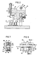
- a double-armed lever 63 is pivotably mounted on a pin 61 parallel to the axis of rotation, as can best be seen from FIG. 3.
- the lever 63 has two arms 65 and 67 projecting approximately diametrically to the pin 61, of which the arm 65 is located on the outside of the pin 61 in the radial direction of the rotor and the arm 67 is located on the inside.
- a leaf spring 69 fastened to the rotor biases the lever 63 in such a pivoting direction that the arm 65 is pivoted towards the positioning pin 57.
- the leaf spring 69 pushes the insert element 11, which is radially inserted from the transport device 19 into the guide chamber 9, towards the positioning pin 57 in the circumferential direction of the rotor 7 and holds the positioning pin 57 in engagement with the positioning recess 59.
- the arm 67 runs on the positioning pin 57 opposite side of the pin 61. Its mass and shape are dimensioned such that its torque caused by the centrifugal acceleration is greater than that of the arm 65, so that it acts as a centrifugal weight which, when the rotor 7 rotates, the cogging force of the leaf spring 69 reinforced.
- the insert element 11 to be pulled out of the guide chamber 9 by the transport device 19 is removed from the locking of the positioning pin 57 by an ejector fork 71 solved.
- the ejector fork 71 can be displaced radially to the rotor 7 in the region of the guide channel 25. 3 and 4, the displacement direction g is indicated by double arrows 73.
- the ejector fork 71 is in the rest position outside the rotational path of the rotor 7. It is carried along by the slide 29 of the transport device 19 and inserted into the rotational path of the rotor 7.
- the ejector fork 71 has an ejector finger 75 and a locking finger 77 on opposite sides of the guide channel 25.
- the ejector finger 75 protruding toward the rotor 7 in the insert element changing position on the side of the positioning pin 57 has at its free end an inclined surface 79 which can be moved over the positioning pin 57 and which lifts the insert element locked to the positioning pin 57 in the circumferential direction of the rotor 7 from the positioning pin 57 .
- the latch finger 77 engages in the insert element changing position on the insert member 11 in the circumferential direction of the rotor 7 side of the pin 61 facing away in a locking channel 81 and locks the rotor eräterahmenfest g.
- the locking finger 77 is dimensioned such that the rotor 7 is locked before the inclined surface 79 begins to eject the insert element 11.
- the locking finger 77 has at its free end a thrust face 83 which cooperates with an associated thrust face 85 of the lever arm 67 and lifts the lever arm 65 against the resistance of the leaf spring 69 from the insert element 11 when the rotor 7 is locked.
- the locking lug 89 and the locking surface 87 are arranged such that the locking surface 91 of the locking lug 89 is outside the movement path of the locking finger 77 when the insert element 11 is properly locked on the positioning pin 57.
- the locking lug 89 engages behind the locking surface 87.
- the locking lug 89 prevents the ejector fork 71 from being pulled back when the insert element 11 is not properly locked, for example when the positioning pin 57 does not enter the positioning recess 59 due to radial misalignment can immerse.
- Control switches (not shown) actuated by the ejector fork 71 prevent the engine 3 from starting up and thus prevent the insert element 11 which is not locked from being thrown off.
- FIG. 3 shows the ejector fork 71 with solid lines in its rest position, that is to say when the rotor 7 is released for rotation.
- the dashed lines in FIG. 3 show the ejector fork 71 in a position in which the rotor 7 has already been locked by the locking finger 77 , but the ejector fork 71 has not yet been pushed so far into the rotor that the ejector finger 75 has released the insert element 11 from its anchoring.
- FIG. 4 shows the ejector fork 71 in the position in which the ejector finger 75 has lifted the insert element 11 from the positioning pin 57 and the locking finger 77 has lifted the lever arm 65 from the insert element 11.
- the indexing of the base plate 55 is controlled by a control pin 97 which is integrally formed on the positioning pin 57.
- the control pin 97 protrudes on the side of the base plate 5 axially facing away from the guide chamber 9 and crosses the beam path of a control light barrier, indicated at 99, which triggers a flash light source or the like of the photometer when the measuring chamber 15 of the insert element 11 crosses the beam path 17. Because the tax pin 97 is integrally formed on the positioning pin 57, the trigger accuracy is increased.
- the positioning accuracy of the measuring chamber 15 relative to the positioning pin 57 can be further increased if insert elements designed as plastic molded parts are used, in which the positioning trough 59 and the cylinder wall of the essentially semi-cylindrical measuring chamber are formed from shaped surfaces of the same one-piece mold part, for example by injection molding.
- the operation of the centrifugal analysis g eräts is controlled according to a predetermined program in accordance with data stored on a magnetic layer 101 (Fig. 6) on a side in the direction of surface of the insert member 11.
- the magnetic layer 101 can carry additional data which serve to identify the sample. If necessary, result data can be stored on the magnetic layer 101.
- the data are read or written by means of a magnetic head unit 103 during the displacement movement of the insert element 11.
- a guide unit 105 guides the insert element 11 while it is being moved past the magnetic head unit 103. 1, the magnetic head unit 103 is arranged in the region of the guide channel 25 between the magazine 21 and the rotor 7.
- the magnetic head unit 103 can, however, also be provided elsewhere, in particular in the area of a device which loads the insert elements of the magazine with liquid samples.
- the magnetic head unit 103 and the guide unit 105 are designed such that the magnetic layer 101 bears over the entire length of the working gap of a magnetic head 107 (FIGS. 6 and 7) of the magnetic head unit 103.
- the magnetic head 107 is on four leaf springs 109 transversely to the direction of displacement of the insert element 11 indicated by an arrow 111 held resiliently deflectable on a frame part 113.
- the frame part 113 is pivotally mounted about an axis of rotation 115 extending in the direction of displacement 111 on flanges 117 fixed to the device frame.
- the guide part 105 carries on a flange 119 fixed to the device frame a guide rail 121 with two guide surfaces 123, 125 inclined towards one another away from the magnetic head 107.
- the guide surfaces 123, 125 inclined towards one another guide the mutually opposite longitudinal edges of the side surface facing away from the magnetic layer 101. Because of this tour you can. Tilt insert element 11 about its longitudinal axis.
- the guide rail 121 is movably guided on the flange 119 at two pins 127 transversely to the displacement direction 111 and is biased by compression springs 129 towards the magnetic head unit 103.
- the rotor 7 is arranged in a housing 141, its interior, which is essentially formed by the guide chambers 9 and accommodates the insert elements, being almost completely closed off from the interior of the housing is.
- the underside of the interior is formed by the already mentioned base plate 55, the upper side by a cover plate 143 or, by a plurality of covers which can be deflected by the gripper of the aforementioned transport device, and which guide the guide chambers 9 upwards. complete.
- the peripheral surface of the rotor 7 is closed by a wall 145 fixed to the housing, which surrounds the peripheral surface at a short distance and essentially only leaves the insertion opening of the insert element changing position open.
- an air duct 149 opens, which supplies warm air from a hot air source consisting of a fan 151 and a heating element 153, which temperature regulates the interior of the rotor 7.
- a second temperature control circuit 163 regulates the temperature of the air inside the housing 141, but outside the rotor 7.
- the control circuit 163 comprises a controller 165, which, depending on the air temperature measured by means of a temperature sensor 169 inside the housing 141, regulates a heating element 167 at one of the controller 161 holds the specified setpoint.
- the heating device 167 is provided in the region of an air inflow opening 173 provided with a fan 171. Embodiments are also expedient in which the heating device overlaps the rotor over a large area.
- the setpoints of the control circuits 159, 163 can be set independently of one another.
- the controllers 155, 165 are preferably PID controllers, that is to say controllers with proportional, integral and differential behavior. With the help of such control loops, the inside temperature of the rotor 7 can be kept constant within very small error limits even during the rotation operation, for example to 37 ° : 0.1 ° C.
- a temperature sensor indicated at 175 in FIG. 8 is arranged in one of the guide chambers. The temperature sensor sits in a housing, the dimensions and shape of which correspond to the shape of the insert elements.
- An optocoupler, shown at 177 transmits the temperature information to the controller 161.
- the energy supply to the temperature sensor 175 takes place via slip rings 179 or by inductive-transformer means.
- the temperature information of the temperature sensor 175 can at least be used to control the setpoint one of the two temperature control loops can be used.
- the controller 161 can be designed such that it changes the setpoint of the control circuit 159 by a predetermined correction amount a predetermined time period before the start of the centrifuging operation, for example reduced at a higher ambient temperature by the counteract subsequent heating by the ambient air sucked in during centrifugation.
- Imbalance vibrations of the rotor have an adverse effect on the measuring accuracy of the centrifugal analysis device.
- the unbalance vibrations can be reduced to a minimum if the loading and unloading of the rotor is controlled by a control system such that after a predetermined number of insert elements determining or determining the maximum unbalance has been added or removed, the same number of insert elements on the substantially diametrically opposite side of the Rotor is fed or removed.
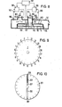
- FIG. 9 schematically shows the rotor, the holders or guide chambers being numbered continuously from 1 to 22 counterclockwise. If only the unbalance caused by a single insert element is permitted, the rotor can be loaded according to the following scheme, for example: 1-12-2-13-3-14- etc. If the unbalance of two insert elements is permitted, the loading scheme could be : 1.2 - 12.13 - 3.4 - 14.15 - etc. The rotor can be unloaded according to an analogous scheme.
- the rotor is rotated about 180 ° in each case after loading or unloading the predetermined number of insert elements.
- the loading or unloading time can be shortened if, after loading or unloading, the predetermined number of adjacent mounts of the rotor in the same direction of loading alternately either the predetermined number of adjacent brackets substantially diametrically opposite holders or the last loaded. sent holders in the direction of loading adjacent predetermined number of holders is loaded or unloaded.
- the loading or unloading scheme could be as follows: 1-12-13-2-3-14-15-, etc. With a maximum imbalance of two insert elements, the loading or unloading scheme is: 1.2-12.13-14.15-3.4-5.6- etc.
- the loading cycle therefore begins at the holder diagonally opposite the temperature element, the loading cycle being counted from the temperature sensor element.
- FIG. 10 schematically shows a rotor 201 which can be used instead of the rotor 7 and which has a flyweight 207 for each holder 203 of an insert element 205.
- the centrifugal weight 207 can be displaced between a radially outer position shown in FIG. 10 below and a radially inner position shown in FIG. 10, for example by inserting the insert element 205. In the radially inner position, the flyweight 207 is locked by the inserted element 205.
- the inner position, the outer position, the mass of the flyweight 207 and the mass of the insert element 205 are dimensioned such that the centrifugal force generated by the flyweight 207 in the outer position in the absence of an insert element is equal to the centrifugal force which the insert element and the centrifugal weight in the inner position is generated. With such a rotor, the holders can be loaded or unloaded at will.
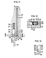
- the F ig. 11 and 12 show another embodiment of a holder for an insert element 211 corresponding to the insert element 11 of FIG. 1.
- the insert element 211 is seated in an essentially radially extending guide channel 213 of a rotor 215 which can be rotated about a central axis of rotation.
- the rotor 215 has a multiplicity of such Guide chambers 213, which are arranged offset about its axis of rotation with equal angular distances.
- the insert elements 211 have an elongated shape and a rectangular cross section.
- a transport device not shown, similar to the transport device 19 in FIG. 1, automatically inserts the insert element 211 into the guide chamber 213 via an opening 217.
- a positioning element 219 is guided on the rotor 215 so as to be displaceable tangentially to the radius direction of the guide chamber 213 to the side of the insertion path g s of each guide chamber 213.
- the positioning element 219 carries at its end facing in the direction of displacement of the guide chamber 213 a positioning bar 221 which in the sliding position distant from the guide chamber 213 releases the insertion cross section of the guide chamber 213 and in the other displacement position engages in a positioning trough 223 of the insert element 211 which is open towards the positioning element 219 .
- the insert element 211 inserted into the guide chamber 213 is pressed by the positioning element 219 against a side wall 225 pointing in the circumferential direction of the rotor 215 and positioned in the circumferential direction.
- the insert element 211 is positioned and locked in the radial direction by the positioning bar 221 which engages in the positioning recess 223.
- the positioning element 219 is shown as a frame in FIG. 12; however, it can also have another shape, for example a U shape.
- a compression spring 227 is provided, which prestresses a pressure piece 231 in a chamber 229 of the rotor 215 essentially radially outwards towards the positioning element 219.
- the radially outer end of the pressure piece 231 passes through one Opening 233 of the positioning element 219, in which a pin 235 attached to the positioning element 219 runs parallel to the axis of rotation of the rotor 215.
- the part of the pressure piece 231 which engages in the opening 233 has a wedge shape and carries a thrust surface 237 which is inclined to the direction of displacement of the thrust piece 231 and is also parallel to the axis of rotation of the rotor 215.
- the thrust surface 237 which engages the pin 235 presses the positioning element 219 under the action of the compression spring 227 to the side surface 225 of the guide chamber 213.
- the angle of attack of the thrust surface 237 to the direction of displacement of the pressure piece 231 is expediently chosen to be less than 45 ° to increase the pressing force.
- an actuating finger 239 is guided in the direction of displacement of the pressure piece 231 on the device frame, not shown.
- the actuating finger 239 which is located outside of the rotational path of the rotor 215 when the rotor is in rotation, engages through a locking opening 241 in the rotor 215 when the insert element is in a changing position and locks it in a rotationally fixed manner.
- the end of the actuating finger 239 facing the pressure piece 231 carries a nose 243, which extends through the opening 233 of the positioning element 219 and can strike against an opposite shoulder 245 of the pressure piece 231.
- the nose 243 lifts the push surface 237 of the pressure piece 231 from the pin 235 of the positioning element 219.
- the actuating finger 239 then carries to the nose 243. a push surface 247 opposite the push surface 237.
- the push surface 247 runs parallel to the pin 235 and obliquely to the directions of displacement of the actuating finger 239 and the positioning element 219.
- the nose 243 is dimensioned such that the actuating finger 239 lifts the pressure piece 231 from the pin 235 and thus relieves the pressure force of the spring 227 before the push surface 247 strikes the pin 235 and the positioning element 219 out of the insertion path of the guide
- Injection molding produced base body 261 in the ones shown, imputed from one of its side areas in unspecified manner, all for Meßre risken erf order - union channels and chambers are formed.
- the channels and chambers are closed by a strip-shaped plate 263, which is tightly fastened, for example, in the ultrasonic welding process.
- the plate 263 has a flat surface and carries a magnetic data carrier layer 265 explained in more detail with reference to FIGS. 6 and 7.
- the side surface opposite the plate 265 follows, as is indicated at 267 for an optical measuring chamber 269 by a broken line, the shape of the Chambers and channels.
- Cheeks 271 are formed on the narrow side surfaces opposite the plate 263 and form guide surfaces along the longitudinal edges of the insert element, which guide the insert element in the guide chamber.
- the insert member carries, based on its rotor position, radially outside the optical measurement chamber 269 is a parallel axes extending transversely to the axis of rotation of the rotor Positioniermulde 273, in which can engage the indicated at 275, also parallel to the axis of the positioning member rotorseiti g en holder.
- the positioning trough (273) opens to the side of the insert element, that is to say transversely to the longitudinal extent of the insert element. It is approximately semicircular.
- the positioning trough 273 and the trough of the optical measuring chamber 269 which is formed closely adjacent to it in the base part 261 are shaped in such a way that they are produced by a one-piece molding tool which does not need to be divided for the demolding process. In this way, the manufacturing tolerances of the positioning recess 273 relative to the optical measuring chamber 269 can be reduced.
- the positioning trough 273 has a contact surface 277 running perpendicular to the longitudinal direction of the insert element which determines the radial position of the insert element relative to the optical beam path of the photometer and a surface 279 running in the longitudinal direction which defines the position in the circumferential direction of the rotor.
- a positioning surface 275 approaches the contact surface 277 with a surface 281 which runs obliquely to the contact surface 277, but which is parallel to the axis of rotation of the rotor, the contact surface 277 completely engaging during the centrifuging operation.
- the contact surface 279 is pressed against the rotor-fixed pin 57 by means of the lever 63.
- FIG. 1 the embodiment according to FIG.
- a surface corresponding to the contact surface 279 is formed by the guide surfaces of the cheeks 271, which bear against the side wall 225.
- the positioning recess 273 can also have a rectangular cross section when viewed in the direction of the rotor axis.
- the contact surfaces of the positioning trough can also be designed in a different way so that they ensure reproducible and exact positioning of the insert element. It is essential that the contact surfaces and the rotor-fixed positioning member 275, which is preferably designed as a pin, do not touch each other over a large area, as would be the case, for example, if the positioning trough 273 were designed to be exactly semicircular with a radius adapted to the pin 275. In this case, even small changes could tolerance 273 result either in the training of Positioniermulde that the Positioniermulde 273 clamped on the pin 275 or has too much play and thus no exact and above all reproducible position gen l vrun- is possible. In contrast, in a construct tion, in which the positioning trough 273 only bears on the pin 275 with two or three narrow, almost linear surfaces, reproducible positioning even at the inevitable tolerances of the production of the positioning trough is guaranteed at all times.
Landscapes
- Physics & Mathematics (AREA)
- Health & Medical Sciences (AREA)
- Life Sciences & Earth Sciences (AREA)
- Chemical & Material Sciences (AREA)
- Analytical Chemistry (AREA)
- Biochemistry (AREA)
- General Health & Medical Sciences (AREA)
- General Physics & Mathematics (AREA)
- Immunology (AREA)
- Pathology (AREA)
- Automatic Analysis And Handling Materials Therefor (AREA)
- Investigating Or Analysing Materials By The Use Of Chemical Reactions (AREA)
- Optical Measuring Cells (AREA)
- Investigating Or Analysing Materials By Optical Means (AREA)
Applications Claiming Priority (2)
| Application Number | Priority Date | Filing Date | Title |
|---|---|---|---|
| DE3314961 | 1983-04-25 | ||
| DE19833314961 DE3314961A1 (de) | 1983-04-25 | 1983-04-25 | Analysegeraet zur photometrischen bestimmung eines parameters einer fluessigkeit |
Publications (2)
| Publication Number | Publication Date |
|---|---|
| EP0132510A2 true EP0132510A2 (fr) | 1985-02-13 |
| EP0132510A3 EP0132510A3 (fr) | 1987-12-16 |
Family
ID=6197322
Family Applications (1)
| Application Number | Title | Priority Date | Filing Date |
|---|---|---|---|
| EP84104572A Withdrawn EP0132510A3 (fr) | 1983-04-25 | 1984-04-24 | Appareil d'analyse pour la détermination photométrique d'un paramètre d'un fluide |
Country Status (4)
| Country | Link |
|---|---|
| US (1) | US4676952A (fr) |
| EP (1) | EP0132510A3 (fr) |
| JP (1) | JPS59208444A (fr) |
| DE (1) | DE3314961A1 (fr) |
Cited By (1)
| Publication number | Priority date | Publication date | Assignee | Title |
|---|---|---|---|---|
| FR2579755A1 (fr) * | 1985-03-26 | 1986-10-03 | Guigan Jean | Procede pour la realisation d'analyses medicales d'un echantillon liquide a l'aide de reactifs secs, et dispositif pour la mise en oeuvre du procede |
Families Citing this family (38)
| Publication number | Priority date | Publication date | Assignee | Title |
|---|---|---|---|---|
| US4695164A (en) * | 1985-09-24 | 1987-09-22 | Boehringer Mannheim Gmbh | Position detector and mount therefor for a centrifugal analyzer |
| US5154889A (en) * | 1986-08-07 | 1992-10-13 | Fuji Photo Film Co., Ltd. | Chemical analysis apparatus |
| US5035861A (en) * | 1987-04-22 | 1991-07-30 | Abbott Laboratories | Locking rack and disposable sample cartridge |
| US4956148A (en) * | 1987-04-22 | 1990-09-11 | Abbott Laboratories | Locking rack and disposable sample cartridge |
| FR2634894B1 (fr) * | 1988-07-28 | 1990-09-14 | Guigan Jean | |
| FR2634892B1 (fr) * | 1988-07-28 | 1990-09-14 | Guigan Jean | Dispositif pour la realisation d'analyses biologiques par detection immuno-enzymatique d'anticorps ou d'antigenes dans un serum |
| US5133936A (en) * | 1988-09-07 | 1992-07-28 | Hitachi, Ltd. | Constant-temperature air type automatic analysis apparatus |
| DE3904201C1 (en) * | 1989-02-13 | 1990-05-03 | Heinrich Amelung Gmbh, 4920 Lemgo, De | Apparatus for the photometric determination of the coagulation behaviour of blood, blood plasma or the like |
| DE4041554A1 (de) * | 1990-12-22 | 1991-05-02 | Komanns Aribert | Verfahren und vorrichtung zur messung der sedimentationskinetik von blutzellen, haemagglutinaten und antigen-antikoerper-komplexen unter einwirkung von zentrifugalkraeften |
| CA2092025A1 (fr) * | 1992-04-06 | 1993-10-07 | Bruno Koch | Porte-recipients pour dispositif d'analyse |
| US5960344A (en) * | 1993-12-20 | 1999-09-28 | Norand Corporation | Local area network having multiple channel wireless access |
| US6143247A (en) | 1996-12-20 | 2000-11-07 | Gamera Bioscience Inc. | Affinity binding-based system for detecting particulates in a fluid |
| US6709869B2 (en) | 1995-12-18 | 2004-03-23 | Tecan Trading Ag | Devices and methods for using centripetal acceleration to drive fluid movement in a microfluidics system |
| DE19631855C2 (de) * | 1996-08-07 | 1998-10-15 | Komanns Aribert | Verfahren und Vorrichtung zur Erfassung von Oberflächenantigenen oder Strukturmerkmalen von Zellen, Partikeln oder Makromolekülen |
| US6143248A (en) * | 1996-08-12 | 2000-11-07 | Gamera Bioscience Corp. | Capillary microvalve |
| WO1998053311A2 (fr) | 1997-05-23 | 1998-11-26 | Gamera Bioscience Corporation | Dispositifs et procedes permettant d'utiliser l'acceleration centripete pour commander le deplacement de fluides sur un systeme microfluidique |
| US6632399B1 (en) * | 1998-05-22 | 2003-10-14 | Tecan Trading Ag | Devices and methods for using centripetal acceleration to drive fluid movement in a microfluidics system for performing biological fluid assays |
| EP1004015B1 (fr) | 1997-08-15 | 2004-01-02 | Alexion Pharmaceuticals, Inc. | Dispositif permettant de realiser des dosages au niveau de sites reactionnels |
| AU759239B2 (en) * | 1997-11-28 | 2003-04-10 | Provalis Diagnostics Limited | Device and apparatus for conducting an assay |
| GB9808836D0 (en) * | 1998-04-27 | 1998-06-24 | Amersham Pharm Biotech Uk Ltd | Microfabricated apparatus for cell based assays |
| US8337753B2 (en) | 1998-05-01 | 2012-12-25 | Gen-Probe Incorporated | Temperature-controlled incubator having a receptacle mixing mechanism |
| ES2286750T3 (es) | 1998-05-01 | 2007-12-01 | Gen-Probe Incorporated | Dispositivo para agitar el contenido liquido de un contenedor. |
| GB9809943D0 (en) * | 1998-05-08 | 1998-07-08 | Amersham Pharm Biotech Ab | Microfluidic device |
| DE19902601A1 (de) * | 1999-01-23 | 2000-07-27 | Roche Diagnostics Gmbh | Verfahren und Vorrichtung zum Entnehmen analytischer Verbrauchsmittel aus einem Vorratsbehältnis |
| US6531095B2 (en) * | 1999-02-11 | 2003-03-11 | Careside, Inc. | Cartridge-based analytical instrument with optical detector |
| US6391264B2 (en) * | 1999-02-11 | 2002-05-21 | Careside, Inc. | Cartridge-based analytical instrument with rotor balance and cartridge lock/eject system |
| US6348176B1 (en) * | 1999-02-11 | 2002-02-19 | Careside, Inc. | Cartridge-based analytical instrument using centrifugal force/pressure for metering/transport of fluids |
| JP2004529312A (ja) * | 1999-06-18 | 2004-09-24 | ガメラ バイオサイエンス コーポレイション | 小型化均一アッセイ用のデバイスおよび方法 |
| GB0021887D0 (en) * | 2000-09-06 | 2000-10-18 | Provalis Diagnostics Ltd | Assay device |
| EP2752668A3 (fr) | 2010-07-23 | 2014-10-15 | Beckman Coulter, Inc. | Système ou procédé comprenant des unités analytiques |
| KR20140091033A (ko) | 2011-11-07 | 2014-07-18 | 베크만 컬터, 인코포레이티드 | 검체 컨테이너 검출 |
| ES2778054T3 (es) | 2011-11-07 | 2020-08-07 | Beckman Coulter Inc | Sistema y método para transportar recipientes de muestras |
| WO2013070755A2 (fr) | 2011-11-07 | 2013-05-16 | Beckman Coulter, Inc. | Système de centrifugeuse et flux de travail |
| CN104040357B (zh) | 2011-11-07 | 2016-11-23 | 贝克曼考尔特公司 | 等分器系统以及工作流 |
| US9446418B2 (en) | 2011-11-07 | 2016-09-20 | Beckman Coulter, Inc. | Robotic arm |
| KR20140091032A (ko) | 2011-11-07 | 2014-07-18 | 베크만 컬터, 인코포레이티드 | 검체 수송 시스템의 자기 감쇠 |
| CN109477775B (zh) * | 2016-07-21 | 2022-05-13 | 西门子医疗保健诊断公司 | 用于临床化学仪器上的杯排的对准系统 |
| US10427162B2 (en) | 2016-12-21 | 2019-10-01 | Quandx Inc. | Systems and methods for molecular diagnostics |
Family Cites Families (9)
| Publication number | Priority date | Publication date | Assignee | Title |
|---|---|---|---|---|
| US3679130A (en) * | 1970-10-30 | 1972-07-25 | Technicon Instr | Container holding rotatable body with adjustable balancing feature |
| US3756920A (en) * | 1971-04-30 | 1973-09-04 | Nasa | In biological samples my measuring light reactions automatic instrument for chemical processing to dedect microorganisms |
| US4135883A (en) * | 1977-08-29 | 1979-01-23 | Bio-Dynamics Inc. | Blood analyzer system |
| US4133642A (en) * | 1978-03-10 | 1979-01-09 | Terumo Corporation | Pipetting apparatus for automatic analyzer |
| US4296070A (en) * | 1980-06-16 | 1981-10-20 | Eastman Kodak Company | Slide distributor for a chemical analyzer |
| US4296069A (en) * | 1980-06-16 | 1981-10-20 | Eastman Kodak Company | Apparatus for processing an analysis slide |
| DE3044385A1 (de) * | 1980-11-25 | 1982-06-24 | Boehringer Mannheim Gmbh, 6800 Mannheim | Verfahren zur durchfuehrung analytischer bestimmungen und hierfuer geeignetes rotoreinsatzelement |
| DE3044372A1 (de) * | 1980-11-25 | 1982-07-08 | Boehringer Mannheim Gmbh, 6800 Mannheim | Rotoreinheit mit einsatzelementen fuer einen zentrifugalanalysator |
| DE3134560A1 (de) * | 1981-09-01 | 1983-03-17 | Boehringer Mannheim Gmbh, 6800 Mannheim | Vorrichtung und verfahren zum steuern und mischen einer der zentrifugalkraft ausgesetzten fluessigkeitsstroemung |
-
1983
- 1983-04-25 DE DE19833314961 patent/DE3314961A1/de not_active Withdrawn
-
1984
- 1984-04-24 EP EP84104572A patent/EP0132510A3/fr not_active Withdrawn
- 1984-04-24 US US06/603,521 patent/US4676952A/en not_active Expired - Fee Related
- 1984-04-25 JP JP59082117A patent/JPS59208444A/ja active Pending
Cited By (2)
| Publication number | Priority date | Publication date | Assignee | Title |
|---|---|---|---|---|
| FR2579755A1 (fr) * | 1985-03-26 | 1986-10-03 | Guigan Jean | Procede pour la realisation d'analyses medicales d'un echantillon liquide a l'aide de reactifs secs, et dispositif pour la mise en oeuvre du procede |
| EP0197866A1 (fr) * | 1985-03-26 | 1986-10-15 | Jean Guigan | Procédé pour la réalisation d'analyses médicales d'un échantillon liquide à l'aide de réactifs secs, et dispositif pour la mise en oeuvre du procédé |
Also Published As
| Publication number | Publication date |
|---|---|
| DE3314961A1 (de) | 1984-10-25 |
| US4676952A (en) | 1987-06-30 |
| JPS59208444A (ja) | 1984-11-26 |
| EP0132510A3 (fr) | 1987-12-16 |
Similar Documents
| Publication | Publication Date | Title |
|---|---|---|
| EP0132510A2 (fr) | Appareil d'analyse pour la détermination photométrique d'un paramètre d'un fluide | |
| DE69510428T2 (de) | Inkubationsvorrichtung | |
| DE2548891C3 (de) | Probenwechsler für Massenspektrometer | |
| DE69214048T2 (de) | Verschlussanordnung der öffnung eines brutschrankes in einem automatischen analysesystem | |
| DE2433411C3 (fr) | ||
| DE69202735T2 (de) | Kalibrierverfahren für ein automatisches analysegerät. | |
| DE60305230T2 (de) | Verfahren zum automatischen Ausrichten eines Mess-Systems für einen klinischen Analysator | |
| DE3689877T2 (de) | Automatische vorrichtung zur analyse von proben. | |
| EP0052770B1 (fr) | Rotor muni de segments amovibles pour analyseur centrifuge | |
| DE4242476C1 (de) | Vorrichtung zum Zentrifugieren von Proben | |
| DE60213873T2 (de) | Stapelbare probengefässanordnung | |
| DE2626810B2 (fr) | ||
| DE102004057450B4 (de) | Automatisches Pipetier- und Analysegerät | |
| DE3905468A1 (de) | Automatische kuevettenbeschickungsvorrichtung | |
| DE2755264A1 (de) | Geraet zur chemischen analyse | |
| US5218894A (en) | Apparatus and method for cutting a pin header | |
| EP2824047B1 (fr) | Dispositif pour séparer des objets en forme de boule ou de cylindre | |
| DE202021004422U1 (de) | Laborgerät mit Fixiermechanismus zum Fixieren eines Objektträgers | |
| DE19813615C2 (de) | Werkzeugkopf | |
| DE69918126T2 (de) | Probenwechsler zum Transfer Radioaktiver Proben zwischen einer heissen Zelle und einer Messvorrichtung | |
| DE69030957T2 (de) | Probentransportsystem für optisches überwachungssystem | |
| DE2552833C3 (de) | Optischer Schnellanalysator vom Drehküvettentyp | |
| DE4203574C2 (de) | Automatische Analysevorrichtung und Verfahren zur automatischen Analyse | |
| DE3204873C2 (de) | Vorrichtung zum automatischen Zuführen einer Probe in den Graphitrohrofen eines Atomabsorptionsspektrometers | |
| AT528502B1 (de) | Vorrichtung und Verfahren zum Analysieren eines Kopfraumgases |
Legal Events
| Date | Code | Title | Description |
|---|---|---|---|
| PUAI | Public reference made under article 153(3) epc to a published international application that has entered the european phase |
Free format text: ORIGINAL CODE: 0009012 |
|
| 17P | Request for examination filed |
Effective date: 19840424 |
|
| AK | Designated contracting states |
Designated state(s): AT BE CH DE FR GB IT LI LU NL SE |
|
| XX | Miscellaneous (additional remarks) |
Free format text: EIN ANTRAG NACH REGEL 88 EPU ZUR AUFNAHME DER FEHLENDEN SEITE 5 DER ANSPRUECHE IN DIE URSPRUENGLICH EINGEREICHTEN ANSPRUECHE VON 24.04.1984 IST AM 22.05.1984 EINGEGANGEN. |
|
| PUAL | Search report despatched |
Free format text: ORIGINAL CODE: 0009013 |
|
| AK | Designated contracting states |
Kind code of ref document: A3 Designated state(s): AT BE CH DE FR GB IT LI LU NL SE |
|
| STAA | Information on the status of an ep patent application or granted ep patent |
Free format text: STATUS: THE APPLICATION IS DEEMED TO BE WITHDRAWN |
|
| 18D | Application deemed to be withdrawn |
Effective date: 19880620 |
|
| RIN1 | Information on inventor provided before grant (corrected) |
Inventor name: HAAR, HANS-PETER, DR. RER. NAT. Inventor name: SATTLER, STEFAN Inventor name: MANN, KARLHEINZ Inventor name: PASCH, MANFRED Inventor name: EDELMANN, HERMANN |