EP0132528A1 - Outil ou raccordement d'outil - Google Patents
Outil ou raccordement d'outil Download PDFInfo
- Publication number
- EP0132528A1 EP0132528A1 EP84105551A EP84105551A EP0132528A1 EP 0132528 A1 EP0132528 A1 EP 0132528A1 EP 84105551 A EP84105551 A EP 84105551A EP 84105551 A EP84105551 A EP 84105551A EP 0132528 A1 EP0132528 A1 EP 0132528A1
- Authority
- EP
- European Patent Office
- Prior art keywords
- tool
- tool holder
- holder according
- memory
- blind hole
- Prior art date
- Legal status (The legal status is an assumption and is not a legal conclusion. Google has not performed a legal analysis and makes no representation as to the accuracy of the status listed.)
- Granted
Links
Images


Classifications
-
- B—PERFORMING OPERATIONS; TRANSPORTING
- B23—MACHINE TOOLS; METAL-WORKING NOT OTHERWISE PROVIDED FOR
- B23B—TURNING; BORING
- B23B31/00—Chucks; Expansion mandrels; Adaptations thereof for remote control
- B23B31/006—Conical shanks of tools
-
- B—PERFORMING OPERATIONS; TRANSPORTING
- B23—MACHINE TOOLS; METAL-WORKING NOT OTHERWISE PROVIDED FOR
- B23Q—DETAILS, COMPONENTS, OR ACCESSORIES FOR MACHINE TOOLS, e.g. ARRANGEMENTS FOR COPYING OR CONTROLLING; MACHINE TOOLS IN GENERAL CHARACTERISED BY THE CONSTRUCTION OF PARTICULAR DETAILS OR COMPONENTS; COMBINATIONS OR ASSOCIATIONS OF METAL-WORKING MACHINES, NOT DIRECTED TO A PARTICULAR RESULT
- B23Q3/00—Devices holding, supporting, or positioning work or tools, of a kind normally removable from the machine
- B23Q3/155—Arrangements for automatic insertion or removal of tools, e.g. combined with manual handling
- B23Q3/1552—Arrangements for automatic insertion or removal of tools, e.g. combined with manual handling parts of devices for automatically inserting or removing tools
- B23Q3/15546—Devices for recognizing tools in a storage device, e.g. coding devices
-
- G—PHYSICS
- G05—CONTROLLING; REGULATING
- G05B—CONTROL OR REGULATING SYSTEMS IN GENERAL; FUNCTIONAL ELEMENTS OF SUCH SYSTEMS; MONITORING OR TESTING ARRANGEMENTS FOR SUCH SYSTEMS OR ELEMENTS
- G05B19/00—Program-control systems
- G05B19/02—Program-control systems electric
- G05B19/04—Program control other than numerical control, i.e. in sequence controllers or logic controllers
- G05B19/12—Program control other than numerical control, i.e. in sequence controllers or logic controllers using record carriers
- G05B19/128—Program control other than numerical control, i.e. in sequence controllers or logic controllers using record carriers the workpiece itself serves as a record carrier, e.g. by its form, by marks or codes on it
-
- B—PERFORMING OPERATIONS; TRANSPORTING
- B23—MACHINE TOOLS; METAL-WORKING NOT OTHERWISE PROVIDED FOR
- B23B—TURNING; BORING
- B23B2231/00—Details of chucks, toolholder shanks or tool shanks
- B23B2231/10—Chucks having data storage chips
-
- Y—GENERAL TAGGING OF NEW TECHNOLOGICAL DEVELOPMENTS; GENERAL TAGGING OF CROSS-SECTIONAL TECHNOLOGIES SPANNING OVER SEVERAL SECTIONS OF THE IPC; TECHNICAL SUBJECTS COVERED BY FORMER USPC CROSS-REFERENCE ART COLLECTIONS [XRACs] AND DIGESTS
- Y10—TECHNICAL SUBJECTS COVERED BY FORMER USPC
- Y10S—TECHNICAL SUBJECTS COVERED BY FORMER USPC CROSS-REFERENCE ART COLLECTIONS [XRACs] AND DIGESTS
- Y10S40/00—Card, picture, or sign exhibiting
- Y10S40/913—Tool identification
-
- Y—GENERAL TAGGING OF NEW TECHNOLOGICAL DEVELOPMENTS; GENERAL TAGGING OF CROSS-SECTIONAL TECHNOLOGIES SPANNING OVER SEVERAL SECTIONS OF THE IPC; TECHNICAL SUBJECTS COVERED BY FORMER USPC CROSS-REFERENCE ART COLLECTIONS [XRACs] AND DIGESTS
- Y10—TECHNICAL SUBJECTS COVERED BY FORMER USPC
- Y10T—TECHNICAL SUBJECTS COVERED BY FORMER US CLASSIFICATION
- Y10T279/00—Chucks or sockets
- Y10T279/21—Chucks or sockets with measuring, indicating or control means
-
- Y—GENERAL TAGGING OF NEW TECHNOLOGICAL DEVELOPMENTS; GENERAL TAGGING OF CROSS-SECTIONAL TECHNOLOGIES SPANNING OVER SEVERAL SECTIONS OF THE IPC; TECHNICAL SUBJECTS COVERED BY FORMER USPC CROSS-REFERENCE ART COLLECTIONS [XRACs] AND DIGESTS
- Y10—TECHNICAL SUBJECTS COVERED BY FORMER USPC
- Y10T—TECHNICAL SUBJECTS COVERED BY FORMER US CLASSIFICATION
- Y10T408/00—Cutting by use of rotating axially moving tool
- Y10T408/21—Cutting by use of rotating axially moving tool with signal, indicator, illuminator or optical means
-
- Y—GENERAL TAGGING OF NEW TECHNOLOGICAL DEVELOPMENTS; GENERAL TAGGING OF CROSS-SECTIONAL TECHNOLOGIES SPANNING OVER SEVERAL SECTIONS OF THE IPC; TECHNICAL SUBJECTS COVERED BY FORMER USPC CROSS-REFERENCE ART COLLECTIONS [XRACs] AND DIGESTS
- Y10—TECHNICAL SUBJECTS COVERED BY FORMER USPC
- Y10T—TECHNICAL SUBJECTS COVERED BY FORMER US CLASSIFICATION
- Y10T408/00—Cutting by use of rotating axially moving tool
- Y10T408/57—Tool-support with means to receive tool-position indicator
-
- Y—GENERAL TAGGING OF NEW TECHNOLOGICAL DEVELOPMENTS; GENERAL TAGGING OF CROSS-SECTIONAL TECHNOLOGIES SPANNING OVER SEVERAL SECTIONS OF THE IPC; TECHNICAL SUBJECTS COVERED BY FORMER USPC CROSS-REFERENCE ART COLLECTIONS [XRACs] AND DIGESTS
- Y10—TECHNICAL SUBJECTS COVERED BY FORMER USPC
- Y10T—TECHNICAL SUBJECTS COVERED BY FORMER US CLASSIFICATION
- Y10T409/00—Gear cutting, milling, or planing
- Y10T409/30—Milling
- Y10T409/30084—Milling with regulation of operation by templet, card, or other replaceable information supply
- Y10T409/300896—Milling with regulation of operation by templet, card, or other replaceable information supply with sensing of numerical information and regulation without mechanical connection between sensing means and regulated means [i.e., numerical control]
-
- Y—GENERAL TAGGING OF NEW TECHNOLOGICAL DEVELOPMENTS; GENERAL TAGGING OF CROSS-SECTIONAL TECHNOLOGIES SPANNING OVER SEVERAL SECTIONS OF THE IPC; TECHNICAL SUBJECTS COVERED BY FORMER USPC CROSS-REFERENCE ART COLLECTIONS [XRACs] AND DIGESTS
- Y10—TECHNICAL SUBJECTS COVERED BY FORMER USPC
- Y10T—TECHNICAL SUBJECTS COVERED BY FORMER US CLASSIFICATION
- Y10T409/00—Gear cutting, milling, or planing
- Y10T409/30—Milling
- Y10T409/30952—Milling with cutter holder
-
- Y—GENERAL TAGGING OF NEW TECHNOLOGICAL DEVELOPMENTS; GENERAL TAGGING OF CROSS-SECTIONAL TECHNOLOGIES SPANNING OVER SEVERAL SECTIONS OF THE IPC; TECHNICAL SUBJECTS COVERED BY FORMER USPC CROSS-REFERENCE ART COLLECTIONS [XRACs] AND DIGESTS
- Y10—TECHNICAL SUBJECTS COVERED BY FORMER USPC
- Y10T—TECHNICAL SUBJECTS COVERED BY FORMER US CLASSIFICATION
- Y10T483/00—Tool changing
- Y10T483/13—Tool changing with control means energized in response to activator stimulated by condition sensor
- Y10T483/132—Responsive to tool identifying information
- Y10T483/134—Identifying information on tool or tool holder
Definitions
- the invention relates to a tool or a tool holder, in particular for machining on numerically controlled machining centers, provided with a data carrier for various tool-specific characteristics such as length, diameter, tool life or the like. Parameter.
- the tool-specific characteristics of the tool with the tool holder are created in a known manner, for example in the form of bar coding, on adhesive labels which are glued to the tool holder.
- the bar coding is scanned with an optical reader, which feeds the data to the control.
- This type of data carrier and data processing has disadvantages.
- the necessary optical readers are very sensitive, not only to mechanical stress, but also to contamination.
- Another disadvantage is the very limited storage capacity of such adhesive labels provided with bar coding; because the bar coding cannot be of any length.
- Another disadvantage is that when the tool is worn, the label bearing the bar coding cannot be seen, whether it is a newly set tool coming from the measuring station or a used tool removed from the machining spindle. For safety reasons, you must therefore remove the stick-on label with bar coding for each tool, if it has been removed from the machine spindle after the machining operation, and stick on a new label with current data in the form of the bar code. These manipulations are complex. In addition, the tool or the tool holder smeared by remaining adhesive layers.
- the invention has for its object to provide a tool or a tool holder in which the aforementioned disadvantages of known data carriers in the form of bar-coded adhesive labels are avoided.
- the invention eliminates the need for a direct connection of the measuring station to the control of the machining center, which means a great deal of effort.
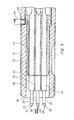
- the schematically indicated tool holder 10 consists e.g. from a chuck for taps or other drills and is especially intended for use in machining on numerically controlled, automatic machining centers.
- the tool holder 10 points in the area where there are standardized surfaces for gripping a gripper 11, which is used for automatic tool change e.g. caused by the tool magazine in the spindle and back, a diametrical blind hole 12.
- the tool holder 10 is provided with a data carrier for various tool-specific characteristics of the structural unit consisting of the tool holder 10 and the inserted tool, e.g. Length, diameter in the cutting area of the tool, service life and the like. other special parameters.
- This data carrier consists in a special design of a permanently installed, electrically erasable, programmable memory 13, also referred to as a so-called EEPROM.
- the memory 13 is soldered on one side of a printed circuit board 14, specifically on the side that points to the bottom of the blind hole 12.
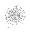
- On the other, externally accessible outside of the printed circuit board 14 there are several, in the exemplary embodiment shown a total of five, mutually insulated and conductively connected to the memory 13 contacts 15 to 19, which are designed here as contact surfaces.
- each individual contact is designed as a contact ring, the individual contact rings being arranged concentrically to one another.
- the memory 13 is protected inside the blind hole 12, in which it also e.g. can be cast in with plastic.
- Contacts 15 and 16 serve e.g. for connection to a voltage supply, while the remaining contacts 17 to 19 are intended for querying, deleting or setting the memory 13.
- the memory 13 does not have its own power supply, which it does not require. It is designed in such a way that it can hold itself even without a power supply.
- the memory 13 is held within the blind hole 12 in a predetermined, reproducible relative rotational position.
- the memory 13 on the one hand and the blind bore 12 on the other hand have associated anti-rotation parts in the form of at least one radial protrusion 50 on the one hand and a groove 51 receiving the protrusion 50 on the other hand, given the relative rotational position.
- the projection 50 is fixedly attached to the memory 13, in particular cast onto it. It extends radially approximately like a nose and extends in the axial direction, for example, over the entire length of the store 13.
- the groove 51 runs axially parallel within the wall of the blind hole 12. This ensures that when the store 13 with circuit board 14 is inserted into the blind hole 12 a fixed, predefined relative installation position is guaranteed to be reproducible.
- the unit Before this unit is entered into a tool magazine of the machining center, there in a predetermined space, the unit is first measured at a measuring station.
- This measuring station has e.g. a by means of a lifting magnet not shown coaxially to the blind hole 12 and to the memory 13 displaceable stamp 20, which has a contact plug 21 at the front end in FIG. 2, which carries individual thin contact pins 22 to 26, of which only those in FIG. 2
- the ends of three contact pins 22, 23 and 24 can be seen, there they are assigned to contacts 15, 18 and 16 has the most protruding part 27-31 at the front end at least one axially projecting tooth with a preferably eccentric or central tip 37-41 to break through contamination when probing and to make good electrical contact.
- the most forwardly projecting parts 27 - 31 have a plurality of axially projecting teeth at the front end, which are placed approximately like crowns.
- each contact pin 22-26 is coupled to the rear part 32-36 so that at the same time as the telescopic insertion of the front part 27-31, the latter is relative to the rear part 32-36 about the axis of the contact pin 22 - 26 can be rotated. So there is a superimposed rotation about the contact pin axis during insertion, so that the tip 37-41 performs a corresponding movement on the surface of the contact 15-19. This may result in dirt or corrosion layers on the top of contacts 15 - 19 broken and torn open. This ensures good electrical contact when making contact, even in the long term. Since the tips 37-41 are located outside the pin axis, rotation of the front portion 27-31 causes the tip 37-41 to travel circumferentially.
- the contact plug 21 has at least one channel 42 which is arranged on the inside in the exemplary embodiment shown and has a front-side blow-out opening 43 through which a compressed gas cleaning jet, in particular a compressed air jet, can exit to the front .
- the channel 42 runs within an insulating insert 44 of the contact plug 21 and stands with a e.g. radial compressed gas supply 45 in connection, to which a pipe or hose 46 can be connected.
- a valve controlling the compressed gas flow which is activated, for example, simultaneously with the insertion of the respective front part 27 - 31 into the rear part 32 - 36 of the contact pins 22 - 26 in the sense of releasing the gas flow.
- This control can also be done manually and independently of the insertion of the respective front parts 27-31. If the compressed gas jet, e.g. Compressed air jet, passed through the channel 42, it exits via the blow-out opening 43 in the direction of the surface carrying the contacts 15-19 and cleans this surface by pressure from dust or similar deposits.
- the compressed gas jet e.g. Compressed air jet
- a plurality of channels corresponding to the channel 42 can be arranged at a suitable location in the insulating insert 44.
- the stamp 20 with the contact plug 21 and its contact pins 22-26 in FIG. 2.6 is moved to the left toward the externally accessible side of the printed circuit board 14, then the individual contact pins 22-26, each for themselves, press on the respectively assigned one Contact 15 to 19, so that the contact is concerned.
- the memory 13 is connected to voltage via the contacts 15 and 16. '' When measuring the unit consisting of tool holder and tool, not only the tool data itself but also e.g. necessary correction data due to wear of the tool can be entered into the memory 13 by setting the memory 13.
- the individual data stored in the memory 13 are then queried in the same way via a stamp 20 with a contact plug 21 and contact pins 22-26 and transferred directly to the machine control system.
- the assembly can be inserted into the tool magazine by hand or e.g. using the automatic tool changing device of the machine, which has a gripper seated in the area of the vertical slide, which grips the machining spindle with one gripper end and grips the new tool located in the tool changing position of the tool magazine with its other gripper end.
- this assembly is used with the tool holder 10 e.g. inserted into the machining spindle and the tool change is then initiated via the gripper.
- the tool-specific data stored in the memory 13 can be interrogated via a stamp 20 with contact plug 21 contact pins 22 to 26 located directly on the gripper 11, and at the same time the transfer and storage in the control of the NC-controlled machining center.
- the advantages of the training according to the invention are as follows. All parameters and other tool-specific data that are required can be stored on the memory IC of the memory 13.
- the memory 13 has a large storage capacity, for example of 32 x 32 bits, which has a multiple of the storage capacity, for example of sticky notes, which - as is already known, for example, in the case of foods and other goods of need - are provided with bar coding.
- the memory 13 ensures data retention for at least 10 years, enables data to be changed on the order of at least 10,000 storage / erase cycles, is also insensitive to magnetic fields and is temperature-resistant, for example up to 125 ° C.
- the memory 13 is a permanent, inseparable part of the tool holder 10, there is no danger that this data carrier will accidentally detach itself from the tool holder 10 and then the data belonging to the tool holder 10 will be lost or mixed up.
- Another advantage is that the memory 13 is otherwise protected against damage or contamination. Due to the training as an electrically erasable, programmable memory, it can be overwritten at any time without any manipulation and need for disassembly, ie it is first deleted and then set again with new data.
- a further advantage is that this opens up the possibility of deleting the stored data completely or partially in the memory 13, for example automatically, when the unit comprising the tool holder 10 and the tool has been inserted in the machining spindle and has been in operation and then the tool change happens. Then namely if the unit was accidentally re-entered into the tool magazine with the risk that this tool would be used again on the machine side without having to run through it
- Tool life that is re-measured and adjusted the unit when the memory 13 is queried cannot be accepted by the tool changer that populates the magazine.
- the structural unit is therefore immediately discarded as such, which is to be fed to the measuring station where the memory is newly set with the new data, in particular correction data relating to the tool. Since the memory 13 holds itself without its own power supply, there is otherwise no danger that stored, tool-specific data will separate from this tool holder 10 with the tool inserted and then be lost.
Landscapes
- Engineering & Computer Science (AREA)
- Mechanical Engineering (AREA)
- Physics & Mathematics (AREA)
- General Physics & Mathematics (AREA)
- Automation & Control Theory (AREA)
- Automatic Tool Replacement In Machine Tools (AREA)
- Machine Tool Sensing Apparatuses (AREA)
Applications Claiming Priority (2)
| Application Number | Priority Date | Filing Date | Title |
|---|---|---|---|
| DE3326615 | 1983-07-23 | ||
| DE19833326615 DE3326615A1 (de) | 1983-07-23 | 1983-07-23 | Werkzeug oder werkzeughalter, insbesondere fuer die zerspanende bearbeitung auf numerisch gesteuerten bearbeitungszentren |
Publications (3)
| Publication Number | Publication Date |
|---|---|
| EP0132528A1 true EP0132528A1 (fr) | 1985-02-13 |
| EP0132528B1 EP0132528B1 (fr) | 1987-11-11 |
| EP0132528B2 EP0132528B2 (fr) | 1993-09-22 |
Family
ID=6204755
Family Applications (1)
| Application Number | Title | Priority Date | Filing Date |
|---|---|---|---|
| EP84105551A Expired - Lifetime EP0132528B2 (fr) | 1983-07-23 | 1984-05-16 | Outil ou raccordement d'outil |
Country Status (4)
| Country | Link |
|---|---|
| US (1) | US4588339A (fr) |
| EP (1) | EP0132528B2 (fr) |
| JP (1) | JPS6025629A (fr) |
| DE (2) | DE3326615A1 (fr) |
Cited By (13)
| Publication number | Priority date | Publication date | Assignee | Title |
|---|---|---|---|---|
| WO1987001798A1 (fr) * | 1985-09-17 | 1987-03-26 | Renishaw Plc | Appareil de changement d'outils |
| EP0191445A3 (fr) * | 1985-02-15 | 1987-04-01 | Elastogran Polyurethane Gmbh | Appareil commandé par programme pour la fabrication de produits à partir d'une matière plastique à plusieurs composants, notamment de polyuréthane |
| GB2185130A (en) * | 1985-11-20 | 1987-07-08 | Tokyo Keiki Kk | Tool holder with tool memory |
| EP0219107A3 (fr) * | 1985-10-15 | 1988-08-24 | Kitamura Machinery Co.,Ltd. | Machine-outil |
| EP0206612A3 (fr) * | 1985-06-11 | 1988-08-31 | Kennametal Erickson U.K. Limited | Adapteur de porte-outil |
| EP0304574A1 (fr) * | 1987-08-07 | 1989-03-01 | Festo KG | Appareil d'alimentation électrique pour une variété d'outils électriques connectables |
| EP0522498A1 (fr) * | 1991-07-10 | 1993-01-13 | DÖRRIES SCHARMANN GmbH | Magazine d'outil avec changeur d'outil |
| US5257199A (en) * | 1985-09-11 | 1993-10-26 | Omron Tateisi Electronics | Apparatus for identifying tools and for managing tool data |
| EP0620108A1 (fr) * | 1993-02-17 | 1994-10-19 | Wilhelm Fette GmbH | Ensemble de poinçons pour une machine de fabrication de comprimés |
| DE19543763A1 (de) * | 1995-11-24 | 1997-05-28 | Leitz Mestechnik Gmbh | Verfahren zur automatischen Erkennung von Sensoren bei Koordinatenmeßgeräten sowie Vorrichtung zur Durchführung des Verfahrens |
| WO2003085468A1 (fr) * | 2002-04-08 | 2003-10-16 | Eder Engineering Gmbh | Systeme de saisie et de memorisation de donnees et procede de saisie et de memorisation de donnees pour outils de precision |
| EP1637946A1 (fr) * | 2004-09-21 | 2006-03-22 | Peter Schöberl | Outil avec une mémoire |
| AT501762B1 (de) * | 2002-04-08 | 2006-11-15 | Eder Engineering Gmbh | Datenerfassung- und datenspeichersystem sowie verfahren zur datenerfassung und -speicherung für präzisionswerkzeuge |
Families Citing this family (77)
| Publication number | Priority date | Publication date | Assignee | Title |
|---|---|---|---|---|
| USRE32837E (en) * | 1982-05-12 | 1989-01-17 | Comau S.P.A. | Coding systems for elements of machine tools, particularly of the numerically controlled type |
| DE3410410A1 (de) * | 1984-03-21 | 1985-09-26 | Maho Werkzeugmaschinenbau Babel & Co, 8962 Pfronten | Werkzeughalter mit datentraeger zur kennung seines werkzeuges |
| JPS61142112A (ja) * | 1985-02-27 | 1986-06-30 | 株式会社 フジパツクシステム | 包装機における包装用フイルム押え装置 |
| JPS61154642U (fr) * | 1985-03-18 | 1986-09-25 | ||
| DE3541676A1 (de) * | 1985-11-26 | 1987-05-27 | Euchner & Co | Identifikationssystem |
| DE3542506A1 (de) * | 1985-12-02 | 1987-06-04 | Kloeckner Humboldt Deutz Ag | Bearbeitungseinrichtung fuer werkstuecke |
| WO1987004960A1 (fr) * | 1986-02-20 | 1987-08-27 | Kievsky Politekhnichesky Institut Imeni 50-Letia V | Systeme de commande du processus de coupe pour machine-outil possedant une commande numerique programmee |
| JPS62219867A (ja) * | 1986-03-20 | 1987-09-28 | Fujitsu Ltd | ファクシミリ装置電源制御装置 |
| JPS62174841U (fr) * | 1986-04-24 | 1987-11-06 | ||
| US4850766A (en) * | 1987-01-09 | 1989-07-25 | Yamazaki Mazaki Corporation | Pull stud |
| US4773800A (en) * | 1987-01-09 | 1988-09-27 | Yamazaki Mazak Corporation | Pull stud |
| JPH0657379B2 (ja) * | 1987-02-10 | 1994-08-03 | 株式会社トキメック | 自動工具交換装置 |
| JPS63245358A (ja) * | 1987-03-30 | 1988-10-12 | Toyoda Mach Works Ltd | 工具ホルダ |
| JPS63274113A (ja) * | 1987-05-06 | 1988-11-11 | Tanaka Kikinzoku Kogyo Kk | 摺動接点装置 |
| JPS63274112A (ja) * | 1987-05-06 | 1988-11-11 | Tanaka Kikinzoku Kogyo Kk | 摺動接点装置 |
| JPS6416244U (fr) * | 1987-07-17 | 1989-01-26 | ||
| JPH065076Y2 (ja) * | 1987-07-17 | 1994-02-09 | オークマ株式会社 | 工具情報の読み書き装置 |
| US4875275A (en) * | 1987-12-07 | 1989-10-24 | Megamation Incoporated | Novel automatic tool changer |
| US5018266A (en) * | 1987-12-07 | 1991-05-28 | Megamation Incorporated | Novel means for mounting a tool to a robot arm |
| JPH0295538A (ja) * | 1988-09-27 | 1990-04-06 | Osaka Kiko Co Ltd | 工作機械の工具段取り装置 |
| DE3833072A1 (de) * | 1988-09-29 | 1990-04-12 | Siri Automation Ind Elektronik | Werkzeugsicherung fuer die werkzeuge von schnitt- oder umformpressen, vornehmlich zur metallbearbeitung |
| JPH04201124A (ja) * | 1990-11-30 | 1992-07-22 | Mitsubishi Electric Corp | 放電加工用電極およびその装置 |
| JP2532756B2 (ja) * | 1991-03-12 | 1996-09-11 | 松下電器産業株式会社 | 部品供給装置の自動交換装置 |
| US5208436A (en) * | 1991-04-12 | 1993-05-04 | The Lincoln Electric Company | Plasma torch with identification circuit |
| DE29505853U1 (de) * | 1995-04-11 | 1995-12-07 | Wolni, Günter, 35398 Gießen | Datenträger |
| JP4201094B2 (ja) * | 1997-12-26 | 2008-12-24 | 村田機械株式会社 | プレス機械 |
| DE19814249A1 (de) * | 1998-03-31 | 1999-10-07 | Matuschek Mestechnik Gmbh | Widerstandsschweißvorrichtung |
| US6047579A (en) * | 1998-04-17 | 2000-04-11 | The Minster Machine Company | RF tag attached to die assembly for use in press machine |
| DE19923735B4 (de) * | 1999-05-22 | 2014-05-28 | Feintool International Holding | Fertigungs- und Montageautomat sowie Funktionseinheit, beispielsweise Arbeitsstation oder Werkzeug für einen solchen Automaten |
| SE516546C2 (sv) * | 1999-10-12 | 2002-01-29 | Seco Tools Ab | Anordning vid en verktygsmaskin |
| US6513749B1 (en) | 1999-12-09 | 2003-02-04 | Barmag Ag | Yarn winding machine and method |
| DE10007126B4 (de) * | 2000-02-17 | 2006-06-22 | Paul Müller GmbH & Co. KG Unternehmensbeteiligungen | Spindel mit einem Datenspeicherelement |
| ATE373256T1 (de) * | 2000-07-14 | 2007-09-15 | Trumpf Werkzeugmaschinen Gmbh | System und verfahren zur identifizierung von werkzeugen und/oder werkzeugteilen von werkzeugmaschinen |
| US6568593B2 (en) | 2000-07-14 | 2003-05-27 | Trumpf Gmbh + Co. | System and method for identification of tools and parts of tools for a fabricating machine |
| DE10118034B4 (de) * | 2001-04-11 | 2006-01-26 | Robert Bosch Gmbh | Werkzeugmaschine, die mit verschiedenen Werkzeughaltern koppelbar ist |
| ATE368351T1 (de) * | 2001-05-14 | 2007-08-15 | Innovision Res & Tech Plc | Tragbares kommunikationsgerät zum gebrauch in einem verkaufssystem |
| GB0111722D0 (en) * | 2001-05-14 | 2001-07-04 | Innovision Res & Tech Plc | Component identification |
| US6585628B1 (en) | 2001-05-22 | 2003-07-01 | Dana Corporation | Cutter tool assembly and system |
| DE10129392A1 (de) * | 2001-06-20 | 2003-01-02 | Convenience Food Sys Wallau | Werkzeug mit einem Sensorchip |
| GB0115788D0 (en) * | 2001-06-28 | 2001-08-22 | Renishaw Plc | Tool identification |
| DE10135531A1 (de) * | 2001-07-20 | 2003-03-27 | Reishauer Ag | Verfahren und Vorrichtung zur Erfassung eines Verschleisszustandes von in der Zahnradfertigung eingesetzten Werkzeugen |
| DE10139020A1 (de) * | 2001-08-08 | 2003-03-13 | W & H Dentalwerk Buermoos Ges | Verfahren zur Steuerung und zur Überwachung eines Behandlungssystems sowie Behandlungssystem und Werkzeug für ein solches Behandlungssystem |
| DE10239710A1 (de) * | 2002-08-29 | 2004-03-11 | Aesculap Ag & Co. Kg | Ärztliches Instrument |
| US7025733B2 (en) * | 2003-06-23 | 2006-04-11 | Mcquaid Matthew | Biological fluid collection accessory device |
| DE10336869A1 (de) * | 2003-08-11 | 2005-06-09 | Kennametal Inc. | Werkzeugkupplung |
| US7913533B2 (en) * | 2006-02-16 | 2011-03-29 | Wilson Tool International Inc. | Machine tool cartridge with information storage device, smart cartridge systems, and methods of using smart cartridge systems |
| US7669453B2 (en) * | 2006-02-16 | 2010-03-02 | Wilson Tool International Inc. | Cartridge for machine tool |
| DE102006008395A1 (de) | 2006-02-21 | 2007-08-30 | Reishauer Ag | Rotierendes Werkzeug mit elektronischem Datenträger |
| SE529722C2 (sv) * | 2006-03-14 | 2007-11-06 | Sandvik Intellectual Property | Skärverktygsenhet med inbyggt chips, chipshållare för dylika kroppar, samt don för montering av chipshållare i skärverktygskroppar |
| CN101511529B (zh) * | 2006-08-31 | 2013-01-30 | 法罗技术股份有限公司 | 可去除智能探针、组合系统以及使用坐标测量机的方法 |
| GB0717969D0 (en) * | 2007-09-14 | 2007-10-24 | Renishaw Plc | Module changing for modular probe |
| US8316742B2 (en) * | 2007-12-11 | 2012-11-27 | Kennametal Inc. | Cutting tool with integrated circuit chip |
| EP2271462A2 (fr) * | 2008-03-17 | 2011-01-12 | Christopher A. Suprock | Système d'usinage intelligent et porte-outil intelligent correspondant |
| US8122610B2 (en) | 2008-03-28 | 2012-02-28 | Hexagon Metrology, Inc. | Systems and methods for improved coordination acquisition member comprising calibration information |
| USD599226S1 (en) | 2008-04-11 | 2009-09-01 | Hexagon Metrology, Inc. | Portable coordinate measurement machine |
| JP4866395B2 (ja) * | 2008-06-27 | 2012-02-01 | 小林製薬株式会社 | 薬剤発散器 |
| CN105313270B (zh) * | 2009-06-18 | 2017-09-15 | 博革新元件国际公司 | 保存模具周期计数的监视器及检索模具周期数据的方法 |
| US8883054B2 (en) | 2009-06-18 | 2014-11-11 | Progressive Components International Corporation | Mold monitoring |
| AU2010273749B2 (en) | 2009-06-30 | 2015-04-02 | Hexagon Metrology Ab | Coordinate measurement machine with vibration detection |
| US8151477B2 (en) | 2009-11-06 | 2012-04-10 | Hexagon Metrology Ab | CMM with modular functionality |
| EP2540432B1 (fr) | 2011-06-27 | 2015-07-29 | Trumpf Maschinen AG | Machine de traitement au laser dotée de composants échangeables |
| KR20210012057A (ko) | 2011-10-10 | 2021-02-02 | 프로그래시브 컴포넌츠 인터내셔널 코포레이션 | 툴링 활동들을 모니터링하기 위한 시스템 및 방법 |
| CN102430960B (zh) * | 2011-11-07 | 2014-04-02 | 吉林大学 | 机械手拉刀力及插刀力的测量及记录装置 |
| CN103186808B (zh) * | 2011-12-29 | 2016-03-09 | 鸿富锦精密工业(深圳)有限公司 | 标签座 |
| US8776644B2 (en) | 2012-01-23 | 2014-07-15 | Stanley Black & Decker, Inc. | Electronic identifier attachment for inventory items |
| US8870078B2 (en) | 2012-02-08 | 2014-10-28 | Stanley Black & Decker, Inc. | Hand tool having an electronic identification device |
| US9089952B2 (en) | 2012-08-14 | 2015-07-28 | Stanley Black & Decker, Inc. | Electronic identifier attachments for bits |
| CN102825502A (zh) * | 2012-08-31 | 2012-12-19 | 大连华根机械有限公司 | 用于金属切削机床上的刀具识别结构 |
| CN103394961B (zh) * | 2013-07-19 | 2015-09-30 | 陈锐志 | 一种丝杠变形及应力消除装置 |
| US9759540B2 (en) | 2014-06-11 | 2017-09-12 | Hexagon Metrology, Inc. | Articulating CMM probe |
| US12208480B2 (en) | 2014-08-15 | 2025-01-28 | Baron Investments, Llc | Data collection, transfer and feedback in working tools |
| US10639756B2 (en) * | 2015-06-05 | 2020-05-05 | Gleason Cutting Tools Corporation | Tools with removable information device |
| DE102015121393A1 (de) * | 2015-12-09 | 2017-06-14 | Röhm Gmbh | Werkzeugmaschine |
| NL2018393B1 (nl) * | 2017-02-20 | 2018-09-17 | Wila Bv | Inrichting voor het inklemmen van een gereedschap en werkwijze voor het vervaardigen van een dergelijke inrichting |
| JP7053671B2 (ja) | 2017-06-30 | 2022-04-12 | 株式会社ミツトヨ | 座標測定機用の自己構成要素識別および信号処理システム |
| DE102017117059B4 (de) * | 2017-07-26 | 2026-05-07 | Franz Haimer Maschinenbau Kg | Werkzeugmaschinensystem mit automatischer wuchtprotokollverwertung |
| US20210362281A1 (en) * | 2020-05-20 | 2021-11-25 | Atkinson International, Inc. | Unloader/Pusher Tube Debris Removal System |
Citations (4)
| Publication number | Priority date | Publication date | Assignee | Title |
|---|---|---|---|---|
| DE1652694A1 (de) * | 1968-02-13 | 1971-02-25 | Hermann Kolb Maschinenfabrik | Werkzeugmaschine mit automatischer Werkzeug-Wechseleinrichtung |
| DE2153081A1 (de) * | 1971-10-25 | 1973-05-03 | Hartmuth Thaler | Geschlechtsloser steckverbinder, ein- oder mehrpolig, ohne ziehkraft |
| DE3012491A1 (de) * | 1980-03-31 | 1981-10-08 | Feinmetall Gmbh, 7033 Herrenberg | Kontaktbaustein |
| DE3131823A1 (de) * | 1980-08-15 | 1982-04-22 | Okuma Howa Kikai K.K., Kounan, Aichi | Numerisch gesteuerte werkzeugmaschine |
Family Cites Families (4)
| Publication number | Priority date | Publication date | Assignee | Title |
|---|---|---|---|---|
| US3052011A (en) * | 1958-06-27 | 1962-09-04 | Kearney & Trecker Corp | Machine tool with a mechanical cutting tool changer |
| US3128645A (en) * | 1960-04-18 | 1964-04-14 | Scully Jones & Company | Machine tool changer |
| US3173204A (en) * | 1961-05-23 | 1965-03-16 | Scully Anthony Corp | Control for tool storage matrix, using individual re-settable code data registers |
| CH543931A (de) * | 1971-10-01 | 1973-11-15 | Oerlikon Buehrle Ag | Werkzeughalter mit einem Körper mit einem Innengewinde und mit einem Codeträger |
-
1983
- 1983-07-23 DE DE19833326615 patent/DE3326615A1/de not_active Withdrawn
-
1984
- 1984-05-16 EP EP84105551A patent/EP0132528B2/fr not_active Expired - Lifetime
- 1984-05-16 DE DE8484105551T patent/DE3467312D1/de not_active Expired
- 1984-06-12 JP JP59121673A patent/JPS6025629A/ja active Granted
- 1984-07-02 US US06/626,621 patent/US4588339A/en not_active Expired - Lifetime
Patent Citations (4)
| Publication number | Priority date | Publication date | Assignee | Title |
|---|---|---|---|---|
| DE1652694A1 (de) * | 1968-02-13 | 1971-02-25 | Hermann Kolb Maschinenfabrik | Werkzeugmaschine mit automatischer Werkzeug-Wechseleinrichtung |
| DE2153081A1 (de) * | 1971-10-25 | 1973-05-03 | Hartmuth Thaler | Geschlechtsloser steckverbinder, ein- oder mehrpolig, ohne ziehkraft |
| DE3012491A1 (de) * | 1980-03-31 | 1981-10-08 | Feinmetall Gmbh, 7033 Herrenberg | Kontaktbaustein |
| DE3131823A1 (de) * | 1980-08-15 | 1982-04-22 | Okuma Howa Kikai K.K., Kounan, Aichi | Numerisch gesteuerte werkzeugmaschine |
Non-Patent Citations (2)
| Title |
|---|
| MANFRED WECK "Werkzeugmaschinen", Band 3, Automatisierung und Steuerungstechnik, 1978 VDI-VERLAG GMBH, Dusseldorf Seiten 119-125 seite 125, absatz 1 * |
| SIEMENS BAUTEILE REPORT, 16. Jahrgang, Heft 6, Dezember 1978, Munchen E. GELDER "Mikrocomputer-Subsysteme von AMC" Seiten 205-208 seite 206, produkt}bersicht smp 80/E 121 * |
Cited By (18)
| Publication number | Priority date | Publication date | Assignee | Title |
|---|---|---|---|---|
| EP0191445A3 (fr) * | 1985-02-15 | 1987-04-01 | Elastogran Polyurethane Gmbh | Appareil commandé par programme pour la fabrication de produits à partir d'une matière plastique à plusieurs composants, notamment de polyuréthane |
| EP0206612A3 (fr) * | 1985-06-11 | 1988-08-31 | Kennametal Erickson U.K. Limited | Adapteur de porte-outil |
| US5257199A (en) * | 1985-09-11 | 1993-10-26 | Omron Tateisi Electronics | Apparatus for identifying tools and for managing tool data |
| EP0404275A1 (fr) * | 1985-09-17 | 1990-12-27 | Renishaw plc | Les outils échangeables |
| WO1987001798A1 (fr) * | 1985-09-17 | 1987-03-26 | Renishaw Plc | Appareil de changement d'outils |
| US4890716A (en) * | 1985-10-15 | 1990-01-02 | Kitamura Machinery Co., Ltd. | Machine tool |
| US4991706A (en) * | 1985-10-15 | 1991-02-12 | Kitamura Machinery Co., Ltd. | Machine tool |
| EP0219107A3 (fr) * | 1985-10-15 | 1988-08-24 | Kitamura Machinery Co.,Ltd. | Machine-outil |
| GB2185130A (en) * | 1985-11-20 | 1987-07-08 | Tokyo Keiki Kk | Tool holder with tool memory |
| GB2185130B (en) * | 1985-11-20 | 1989-11-22 | Tokyo Keiki Kk | Information storage apparatus for tool holder |
| EP0304574A1 (fr) * | 1987-08-07 | 1989-03-01 | Festo KG | Appareil d'alimentation électrique pour une variété d'outils électriques connectables |
| EP0522498A1 (fr) * | 1991-07-10 | 1993-01-13 | DÖRRIES SCHARMANN GmbH | Magazine d'outil avec changeur d'outil |
| EP0620108A1 (fr) * | 1993-02-17 | 1994-10-19 | Wilhelm Fette GmbH | Ensemble de poinçons pour une machine de fabrication de comprimés |
| DE19543763A1 (de) * | 1995-11-24 | 1997-05-28 | Leitz Mestechnik Gmbh | Verfahren zur automatischen Erkennung von Sensoren bei Koordinatenmeßgeräten sowie Vorrichtung zur Durchführung des Verfahrens |
| DE19543763B4 (de) * | 1995-11-24 | 2005-07-21 | Leitz Messtechnik Gmbh | Verfahren zur automatischen Erkennung von verschiedenen Sensoren bei Koordinatenmeßgeräten sowie Vorrichtungen zur Durchführung des Verfahrens |
| WO2003085468A1 (fr) * | 2002-04-08 | 2003-10-16 | Eder Engineering Gmbh | Systeme de saisie et de memorisation de donnees et procede de saisie et de memorisation de donnees pour outils de precision |
| AT501762B1 (de) * | 2002-04-08 | 2006-11-15 | Eder Engineering Gmbh | Datenerfassung- und datenspeichersystem sowie verfahren zur datenerfassung und -speicherung für präzisionswerkzeuge |
| EP1637946A1 (fr) * | 2004-09-21 | 2006-03-22 | Peter Schöberl | Outil avec une mémoire |
Also Published As
| Publication number | Publication date |
|---|---|
| DE3326615A1 (de) | 1985-01-31 |
| JPH0415053B2 (fr) | 1992-03-16 |
| DE3467312D1 (en) | 1987-12-17 |
| EP0132528B2 (fr) | 1993-09-22 |
| US4588339A (en) | 1986-05-13 |
| JPS6025629A (ja) | 1985-02-08 |
| EP0132528B1 (fr) | 1987-11-11 |
Similar Documents
| Publication | Publication Date | Title |
|---|---|---|
| EP0132528A1 (fr) | Outil ou raccordement d'outil | |
| DE69207109T2 (de) | Werkzeugmaschine | |
| DE9307155U1 (de) | Automatische Drehmaschine | |
| DE69320471T2 (de) | Universalrevolversystem für schnellwechseldrehmaschinenwerkzeuge | |
| EP3456466A1 (fr) | Magasin à outils et procédé de changement d'outils | |
| DE202009018934U1 (de) | Werkzeugmaschine | |
| DE10307030A1 (de) | Dosiersystem | |
| DE102016121160B4 (de) | Lötanlage | |
| DE2624599C2 (de) | Rotierender Werkzeughalter mit einem in ihm aufgenommenen Zerspanungswerkzeug | |
| EP0003024B1 (fr) | Système de fabrication flexible | |
| EP0185889A2 (fr) | Dispositif de serrage d'outil en particulier pour fraiseuses et aléseuses | |
| DE3634018C2 (fr) | ||
| WO2008019683A1 (fr) | Broche avec barre de traction et conducteur électrique | |
| EP0427661A2 (fr) | Identification d'outil | |
| DE29612760U1 (de) | Vorrichtung zum Zuführen und Montieren von ringförmigen Elementen wie z.B. Dichtungsringen, besonders im gefetteten oder geölten Zustand | |
| DE3873915T2 (de) | Vorrichtung zum positionieren und blockieren auf dem spindelkopf einer werkzeugmaschine von verschiedenen einrichtungen zur mechanischen bearbeitung. | |
| DE2805828A1 (de) | Drehmaschine mit automatischem spannbackenwechsel | |
| EP0092673A2 (fr) | Porte-outil pour supporter les outils de tournage d'un système | |
| DE10206164B4 (de) | Einspannschaft | |
| DE3629097C2 (fr) | ||
| EP1308788A2 (fr) | Dispositif pour l'alignement d'un masque photolithographique | |
| DE3524434C1 (de) | Werkzeugmaschinenspindel und hierzu passende Werkzeughalter | |
| DE2345772C2 (de) | Vorrichtung zur selbsttätigen Eingabe von Werkstücken mit einer inneren Bohrung in Werkzeugmaschinen | |
| EP1109649A1 (fr) | Machine-outil | |
| DE2525754C2 (de) | Werkzeugträger eines Werkzeugträger-Speichers einer Werkstück-Bearbeitungsmaschine |
Legal Events
| Date | Code | Title | Description |
|---|---|---|---|
| PUAI | Public reference made under article 153(3) epc to a published international application that has entered the european phase |
Free format text: ORIGINAL CODE: 0009012 |
|
| AK | Designated contracting states |
Designated state(s): CH DE FR GB IT LI SE |
|
| 17P | Request for examination filed |
Effective date: 19850321 |
|
| 17Q | First examination report despatched |
Effective date: 19860321 |
|
| GRAA | (expected) grant |
Free format text: ORIGINAL CODE: 0009210 |
|
| AK | Designated contracting states |
Kind code of ref document: B1 Designated state(s): CH DE FR GB IT LI SE |
|
| REF | Corresponds to: |
Ref document number: 3467312 Country of ref document: DE Date of ref document: 19871217 |
|
| ET | Fr: translation filed | ||
| ITF | It: translation for a ep patent filed | ||
| GBT | Gb: translation of ep patent filed (gb section 77(6)(a)/1977) | ||
| PLBI | Opposition filed |
Free format text: ORIGINAL CODE: 0009260 |
|
| PLBI | Opposition filed |
Free format text: ORIGINAL CODE: 0009260 |
|
| PLAB | Opposition data, opponent's data or that of the opponent's representative modified |
Free format text: ORIGINAL CODE: 0009299OPPO |
|
| PLAB | Opposition data, opponent's data or that of the opponent's representative modified |
Free format text: ORIGINAL CODE: 0009299OPPO |
|
| 26 | Opposition filed |
Opponent name: GEBHARD BALLUFF FABRIK FEINMECHANISCHER ERZEUGNISS Effective date: 19880806 Opponent name: KRUPP WIDIA GMBH Effective date: 19880802 |
|
| 26 | Opposition filed |
Opponent name: SUSUMU FUNAKOSHI Effective date: 19880810 Opponent name: GEBHARD BALLUFF FABRIK FEINMECHANISCHER ERZEUGNISS Effective date: 19880806 Opponent name: KRUPP WIDIA GMBH Effective date: 19880802 |
|
| R26 | Opposition filed (corrected) |
Opponent name: KRUPP WIDIA GMBH * 880826 GEBHARD BALLUFF FABRIK F Effective date: 19880802 |
|
| R26 | Opposition filed (corrected) |
Opponent name: KRUPP WIDIA GMBH * 880806 GEBHARD BALLUFF FABRIK F Effective date: 19880802 |
|
| ITTA | It: last paid annual fee | ||
| PUAH | Patent maintained in amended form |
Free format text: ORIGINAL CODE: 0009272 |
|
| STAA | Information on the status of an ep patent application or granted ep patent |
Free format text: STATUS: PATENT MAINTAINED AS AMENDED |
|
| 27A | Patent maintained in amended form |
Effective date: 19930922 |
|
| AK | Designated contracting states |
Kind code of ref document: B2 Designated state(s): CH DE FR GB IT LI SE |
|
| ET3 | Fr: translation filed ** decision concerning opposition | ||
| REG | Reference to a national code |
Ref country code: CH Ref legal event code: AEN |
|
| GBTA | Gb: translation of amended ep patent filed (gb section 77(6)(b)/1977) |
Effective date: 19930922 |
|
| ITF | It: translation for a ep patent filed | ||
| REG | Reference to a national code |
Ref country code: GB Ref legal event code: 746 Effective date: 19940301 |
|
| EAL | Se: european patent in force in sweden |
Ref document number: 84105551.0 |
|
| PGFP | Annual fee paid to national office [announced via postgrant information from national office to epo] |
Ref country code: FR Payment date: 19950517 Year of fee payment: 12 |
|
| PGFP | Annual fee paid to national office [announced via postgrant information from national office to epo] |
Ref country code: SE Payment date: 19950523 Year of fee payment: 12 |
|
| PGFP | Annual fee paid to national office [announced via postgrant information from national office to epo] |
Ref country code: CH Payment date: 19950621 Year of fee payment: 12 |
|
| PG25 | Lapsed in a contracting state [announced via postgrant information from national office to epo] |
Ref country code: SE Effective date: 19960517 |
|
| PG25 | Lapsed in a contracting state [announced via postgrant information from national office to epo] |
Ref country code: LI Effective date: 19960531 Ref country code: CH Effective date: 19960531 |
|
| REG | Reference to a national code |
Ref country code: CH Ref legal event code: PL |
|
| PG25 | Lapsed in a contracting state [announced via postgrant information from national office to epo] |
Ref country code: FR Effective date: 19970131 |
|
| EUG | Se: european patent has lapsed |
Ref document number: 84105551.0 |
|
| REG | Reference to a national code |
Ref country code: FR Ref legal event code: ST |
|
| REG | Reference to a national code |
Ref country code: CH Ref legal event code: AEN Free format text: AUFRECHTERHALTUNG DES PATENTES IN GEAENDERTER FORM |
|
| PGFP | Annual fee paid to national office [announced via postgrant information from national office to epo] |
Ref country code: GB Payment date: 19990315 Year of fee payment: 16 |
|
| PGFP | Annual fee paid to national office [announced via postgrant information from national office to epo] |
Ref country code: DE Payment date: 19990716 Year of fee payment: 16 |
|
| PG25 | Lapsed in a contracting state [announced via postgrant information from national office to epo] |
Ref country code: GB Free format text: LAPSE BECAUSE OF NON-PAYMENT OF DUE FEES Effective date: 20000516 |
|
| GBPC | Gb: european patent ceased through non-payment of renewal fee |
Effective date: 20000516 |
|
| PG25 | Lapsed in a contracting state [announced via postgrant information from national office to epo] |
Ref country code: DE Free format text: LAPSE BECAUSE OF NON-PAYMENT OF DUE FEES Effective date: 20010301 |
|
| APAH | Appeal reference modified |
Free format text: ORIGINAL CODE: EPIDOSCREFNO |