EP0132779A2 - Dormant de fenêtre - Google Patents
Dormant de fenêtre Download PDFInfo
- Publication number
- EP0132779A2 EP0132779A2 EP84108481A EP84108481A EP0132779A2 EP 0132779 A2 EP0132779 A2 EP 0132779A2 EP 84108481 A EP84108481 A EP 84108481A EP 84108481 A EP84108481 A EP 84108481A EP 0132779 A2 EP0132779 A2 EP 0132779A2
- Authority
- EP
- European Patent Office
- Prior art keywords
- window
- window frame
- frame according
- frame
- wings
- Prior art date
- Legal status (The legal status is an assumption and is not a legal conclusion. Google has not performed a legal analysis and makes no representation as to the accuracy of the status listed.)
- Withdrawn
Links
- 238000009423 ventilation Methods 0.000 claims abstract description 9
- 238000009413 insulation Methods 0.000 claims abstract description 5
- 239000011810 insulating material Substances 0.000 claims description 2
- 238000009434 installation Methods 0.000 abstract description 2
- XLYOFNOQVPJJNP-UHFFFAOYSA-N water Substances O XLYOFNOQVPJJNP-UHFFFAOYSA-N 0.000 abstract 1
- 238000007789 sealing Methods 0.000 description 8
- 238000010276 construction Methods 0.000 description 5
- 239000000463 material Substances 0.000 description 5
- 239000011521 glass Substances 0.000 description 4
- 238000004519 manufacturing process Methods 0.000 description 4
- 239000011505 plaster Substances 0.000 description 4
- XEEYBQQBJWHFJM-UHFFFAOYSA-N Iron Chemical compound [Fe] XEEYBQQBJWHFJM-UHFFFAOYSA-N 0.000 description 3
- 241000255925 Diptera Species 0.000 description 2
- 238000006073 displacement reaction Methods 0.000 description 2
- 230000000694 effects Effects 0.000 description 2
- 239000005357 flat glass Substances 0.000 description 2
- 239000002184 metal Substances 0.000 description 2
- 229910052751 metal Inorganic materials 0.000 description 2
- 229920005830 Polyurethane Foam Polymers 0.000 description 1
- 238000000149 argon plasma sintering Methods 0.000 description 1
- 230000005540 biological transmission Effects 0.000 description 1
- 238000005266 casting Methods 0.000 description 1
- 238000004140 cleaning Methods 0.000 description 1
- 238000011109 contamination Methods 0.000 description 1
- 238000010616 electrical installation Methods 0.000 description 1
- 239000006260 foam Substances 0.000 description 1
- 238000005286 illumination Methods 0.000 description 1
- 238000003780 insertion Methods 0.000 description 1
- 230000037431 insertion Effects 0.000 description 1
- 229910052742 iron Inorganic materials 0.000 description 1
- 230000004048 modification Effects 0.000 description 1
- 238000012986 modification Methods 0.000 description 1
- 229920002635 polyurethane Polymers 0.000 description 1
- 239000004814 polyurethane Substances 0.000 description 1
- 239000011496 polyurethane foam Substances 0.000 description 1
- 230000002787 reinforcement Effects 0.000 description 1
- 239000012858 resilient material Substances 0.000 description 1
- 239000012780 transparent material Substances 0.000 description 1
Images


Classifications
-
- E—FIXED CONSTRUCTIONS
- E06—DOORS, WINDOWS, SHUTTERS, OR ROLLER BLINDS IN GENERAL; LADDERS
- E06B—FIXED OR MOVABLE CLOSURES FOR OPENINGS IN BUILDINGS, VEHICLES, FENCES OR LIKE ENCLOSURES IN GENERAL, e.g. DOORS, WINDOWS, BLINDS, GATES
- E06B7/00—Special arrangements or measures in connection with doors or windows
- E06B7/02—Special arrangements or measures in connection with doors or windows for providing ventilation, e.g. through double windows; Arrangement of ventilation roses
- E06B7/10—Special arrangements or measures in connection with doors or windows for providing ventilation, e.g. through double windows; Arrangement of ventilation roses by special construction of the frame members
-
- E—FIXED CONSTRUCTIONS
- E06—DOORS, WINDOWS, SHUTTERS, OR ROLLER BLINDS IN GENERAL; LADDERS
- E06B—FIXED OR MOVABLE CLOSURES FOR OPENINGS IN BUILDINGS, VEHICLES, FENCES OR LIKE ENCLOSURES IN GENERAL, e.g. DOORS, WINDOWS, BLINDS, GATES
- E06B1/00—Border constructions of openings in walls, floors, or ceilings; Frames to be rigidly mounted in such openings
- E06B1/02—Base frames, i.e. template frames for openings in walls or the like, provided with means for securing a further rigidly-mounted frame; Special adaptations of frames to be fixed therein
-
- E—FIXED CONSTRUCTIONS
- E06—DOORS, WINDOWS, SHUTTERS, OR ROLLER BLINDS IN GENERAL; LADDERS
- E06B—FIXED OR MOVABLE CLOSURES FOR OPENINGS IN BUILDINGS, VEHICLES, FENCES OR LIKE ENCLOSURES IN GENERAL, e.g. DOORS, WINDOWS, BLINDS, GATES
- E06B1/00—Border constructions of openings in walls, floors, or ceilings; Frames to be rigidly mounted in such openings
- E06B1/04—Frames for doors, windows, or the like to be fixed in openings
- E06B1/26—Frames of plastics
- E06B1/28—Hollow frames
-
- E—FIXED CONSTRUCTIONS
- E06—DOORS, WINDOWS, SHUTTERS, OR ROLLER BLINDS IN GENERAL; LADDERS
- E06B—FIXED OR MOVABLE CLOSURES FOR OPENINGS IN BUILDINGS, VEHICLES, FENCES OR LIKE ENCLOSURES IN GENERAL, e.g. DOORS, WINDOWS, BLINDS, GATES
- E06B3/00—Window sashes, door leaves, or like elements for closing wall or like openings; Layout of fixed or moving closures, e.g. windows in wall or like openings; Features of rigidly-mounted outer frames relating to the mounting of wing frames
- E06B3/32—Arrangements of wings characterised by the manner of movement; Arrangements of movable wings in openings; Features of wings or frames relating solely to the manner of movement of the wing
- E06B3/48—Wings connected at their edges, e.g. foldable wings
- E06B3/481—Wings foldable in a zig-zag manner or bi-fold wings
-
- E—FIXED CONSTRUCTIONS
- E06—DOORS, WINDOWS, SHUTTERS, OR ROLLER BLINDS IN GENERAL; LADDERS
- E06B—FIXED OR MOVABLE CLOSURES FOR OPENINGS IN BUILDINGS, VEHICLES, FENCES OR LIKE ENCLOSURES IN GENERAL, e.g. DOORS, WINDOWS, BLINDS, GATES
- E06B3/00—Window sashes, door leaves, or like elements for closing wall or like openings; Layout of fixed or moving closures, e.g. windows in wall or like openings; Features of rigidly-mounted outer frames relating to the mounting of wing frames
- E06B3/04—Wing frames not characterised by the manner of movement
- E06B3/06—Single frames
- E06B3/08—Constructions depending on the use of specified materials
- E06B3/20—Constructions depending on the use of specified materials of plastics
- E06B3/22—Hollow frames
- E06B3/221—Hollow frames with the frame member having local reinforcements in some parts of its cross-section or with a filled cavity
Definitions
- Window frames also consist of simple metal or wooden frames, which may have part of the fittings required to operate the windows. If the window is to be provided with accessories, the necessary work steps are multiplied. Examples include only accessories such as window sills, thermal and acoustic insulation, special weather bars, additional ventilation devices or roller shutters that can be used when the window is closed, with their roller blind boxes, roller blinds, belt boxes and guide rails, the assembly of which often takes considerably more time if the various operations are not properly coordinated as a necessary claim and causes anger and complaints.
- accessories such as window sills, thermal and acoustic insulation, special weather bars, additional ventilation devices or roller shutters that can be used when the window is closed, with their roller blind boxes, roller blinds, belt boxes and guide rails, the assembly of which often takes considerably more time if the various operations are not properly coordinated as a necessary claim and causes anger and complaints.
- the windows mainly used today consist of a window frame to be inserted into the wall opening and at least one sash frame that is rotatably and / or tiltably attached to it and supports the glazing.
- the frame construction uses a lot of material. This material consumption would increase if a window frame was additionally provided.
- the operation of most turning and / or tilting devices is cumbersome, especially when it comes to larger wings, and there is often the risk that the wings disengage and then only partially in the turning and / or tilting device are held.
- the incidence of light that can be achieved per wall opening is limited due to the space-consuming frame and possibly frame construction.
- the invention has for its object to reduce the number of operations in the construction of a window, particularly in those cases in which accessories should be provided in addition to the window itself.
- a window is to be created which allows a relatively large amount of light and an assembly at least without a frame, but preferably also without a sash and a simple and safe opening and closing of the window sash.
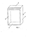
- the invention provides a window frame which is already provided with the required or desired accessories for the window and is designed together with these as a prefabricated structural unit.
- a window which is particularly suitable for such a window frame consists of a double-leaf folding window, the leaves of which only consist of the glazing and a surrounding frame and are rotatably and displaceably mounted in guide rails of the window frame by means of pivot pins.
- the invention has the advantage that the accessories are not attached to the windows themselves or the surrounding wall, but to an independent window frame. This makes it possible, on the one hand, to maintain the previous variety of types in the manufacture of the windows, and, on the other hand, to considerably simplify the ordering and assembly of accessories, since these are already integrated in the window frame.
- the new folding window has the particular advantage that the usual blind and casement frames are eliminated, an optimal light transmission is achieved and no complex rotating and / or tilting devices are required.
- the window frame 1 is inserted as a whole into a wall opening 6 which is delimited at the bottom by a parapet 7, laterally by wall parts 8 and 9 and at the top by a ceiling 10 or a lintel 11.
- the parapet 12 and the floating screed 13 of a floor above are also indicated above the ceiling 10.
- the actual window is inserted into the frame 1 and, as usual, can consist of a frame 14, a casement 15 and insulating glass 16.
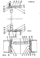
- the window frame consists from the inside to the outside of an inner part 18, a middle part 19 supporting the window and an outer part 20, each of which abuts all around the wall sections delimiting the wall opening 6 and, according to FIGS. 3 and 4, each of floor, side and ceiling elements are composed, which in their entirety form the floor, side and ceiling elements 2 to 5 of the finished window frame 1.
- the inner part 18 consists of a plate-shaped hollow profile which, for reinforcement by intermediate webs 21, is divided into a plurality of chambers which are filled with air or another heat and / or sound-insulating material 22, for example foamed with polyurethane foam.
- the intermediate part 19 is designed accordingly and, for manufacturing reasons, advantageously has the same shape and size.
- Ventilation is not shown in the middle part 19. slits worked in, covered on the outside by a fly screen 23, on the inside, however, by a ventilation slide or the like and incorporated tete slats or the like are provided with sound-absorbing deflections for the air flow. As a result, ventilation can also be carried out when the window is closed, as indicated by arrows 25.
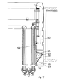
- Such additional ventilation units can be provided according to FIG. 5 in the ceiling element and / or according to FIG. 6 in the side elements.
- the outer part 20 is composed of profiles, possibly also hollow profiles, which are formed in the area of the side parts and the top part as a panel 27 which gives the outside of the window a pleasing appearance.
- the outer part 20 is designed as a weather leg 28 (FIG. 5) which extends over the width of the wall opening 6 and which promotes the outflow of rainwater in the usual way.
- the inner part 18, the middle part 19 and the outer part 20 are connected in the factory to form a fixed structural unit.
- the window frame 1 is attached to the construction site in the wall opening 6.
- the base element of the frame 1 expediently has dovetail-shaped grooves 29, into which a plaster or food layer 30 freshly applied to the parapet 7 penetrates during assembly, which locks the frame 1 after hardening.
- the remaining gaps between the side parts 3, 4 and the adjacent wall sections can also be filled with foam. If necessary, especially with large heights, the frame can also be fixed in the wall opening using screws and dowels.
- the bottom elements of the inner and middle part are expediently flat, so that they can serve as a window sill. If required, however, a window sill 31 designed as usual can also be attached to these floor elements and, for example, glued to them.
- the window can already be inserted in the frame at the factory.
- the frame 1 can be provided with a stop and quick-release fasteners for the window so that it can be installed in just a few steps after installing the frame 1.
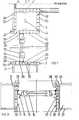
- the inner part 36 is designed according to FIGS. 5 and 6, but it consists only of a bottom element and two side elements. One of these side elements is provided with a belt box 40.
- the middle part 37 likewise has no ceiling part and is also shorter in comparison to FIG. 5,6 in that it only has three hollow chambers instead of four.
- the missing section of the middle part is replaced by the guide part 38, which consists of a U-shaped guide rail serving as a lateral guide for a roller blind web 41.
- the guide part 38 can consist of a likewise foamed hollow profile with a U-shaped recess.
- the guide part 38 is composed of side elements and a base element. 8 expediently protrudes somewhat further into the wall opening than the inner part 36 and the central part 37, so that it can simultaneously serve as a stop for the window.
- the outer part 39 is essentially designed in accordance with FIGS. 5, 6 and is also provided with a ceiling element 42 (FIG. 7).
- the ceiling element is essentially formed by a roller blind box 43, in which a roller blind shaft 44 is rotatable is device that carries the roller blind 41.
- the roller blind box 43 is composed of four plate-shaped hollow profiles 46, 47, 48 and 49, at least the inner hollow profiles 47, 48 and 49 being foamed with polyurethane or the like in order to obtain adequate heat and sound insulation.
- the outer hollow profile 46 is connected at its lower end to the ceiling element 42 of the outer part 39 and is otherwise covered with the outer plaster 33.
- the upper hollow profile 47 lies against the ceiling 10 or against the lintel 11.
- the inner, vertically arranged hollow profile 48 has a removable flap 50, which allows access to the roller mechanism, while the lower hollow profile 49 is provided with a slot 51 arranged outside the window for the passage of the blind sheet 41 and is supported on the frame 14.
- a frame intended for receiving a folding window consists from the inside to the outside of an inner part 59, a middle part 60 supporting the window, possibly a guide part 61 and an outer part 62, into which accessories are integrated according to FIGS. 1 to 8 are, e.g. a venetian blind 69, which is accommodated in a box 70 arranged below the ceiling or the lintel and is mounted in guides of the guide part 61 so as to be movable up and down.
- a venetian blind 69 which is accommodated in a box 70 arranged below the ceiling or the lintel and is mounted in guides of the guide part 61 so as to be movable up and down.
- the middle part 60 of the frame each has a U-shaped recess extending over the length of its side elements, into each of which a seal 72, preferably made of a flexible material, is inserted.
- a lower and upper guide rail 73, 74 is arranged at the lower and upper ends of the seals 72, so that a frame with a rectangular cross section, parallel to the central plane of the wall opening, is formed in the opening left free of the frame and laterally from the seals 72 , below and above, however, is formed by the guide rails 73, 74.
- the guide rails are fastened to the associated frame parts or are produced in one piece with them, while the seals 72 are glued, for example, into the U-shaped recesses. Otherwise, the guide rails are provided with continuous, U-shaped guide grooves 75.
- the frame and the accessories, which also include the seals and the guide rails 75, form a prefabricated structural unit.
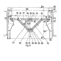
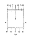
- a preferred embodiment of the folding window according to the invention contains two wings 76, 77 of the same size, symmetrically designed and arranged and each carrying glazing.
- the glazing is e.g. formed as a known multi-glazing.
- Each wing 76, 77 is surrounded all around with a narrow bezel 78, which serves only as the end of the glazing in the form of a e.g. made of metal or plastic-U-profile or the like., which replaces the previous casement and can be made much lighter and smaller than this by the dimension b (Fig. 12) is for example one or two centimeters.
- Lower and upper base plates 79, 80 which extend over the entire width of the respective leaf 76, 77, are fastened to the parts of the casing 78 that run parallel to the lower edge or upper edge of the leaf.
- the base plates serve on the one hand to seal the lower edges or upper edges of the wings against the associated guide rails, and on the other hand are provided near their outer corner points bordering the wall parts or the frame with lower or upper pivot pins 81, 82, the axes of rotation of which are parallel to one another and are arranged parallel to the side edges of the wings 76, 77.
- the surrounds 78 can also be omitted in whole or in part and the pivot pins can be connected to the glazing in another way.
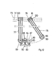
- the inner, mutually facing side edges of the two wings 76, 77 are pivotally connected to one another over their entire length by a center post 83 according to FIG. 9.
- the radii of the contact surfaces 85.86 be carry, for example, about half the thickness of the wings 76, 77.
- the cylinder axes lie approximately in the median plane of the wing.
- fastening pins 88 can be provided on the upper or lower end of the middle post 83, onto each of which an end of a clamp element 87 having a corresponding recess is pressed in the manner of a snap connection, while the other end, which likewise has a recess, is correspondingly pressed onto fastening pins 89 is pressed, which are mounted coaxially to the axes of the contact surfaces 85, 86 on the upper and lower parts of the casing 78.
- the window according to the invention is inserted in the manner shown in FIGS. 9 and 10 into the wall opening left free of the frame in such a way that the pivot pins 81, 82 enter the guide grooves 75, for which purpose the guide rails 73, 74 with suitable lateral insertion openings can be provided, which are closed after assembly.
- the pivots 81, 82 are now rotatable in the guide grooves 75 and can be displaced in the longitudinal direction thereof.
- a pull on a handle 90 attached to the mullion 83 towards the inside of the room having the wall opening therefore has the result that the facing side edges of the wings 76, 77 are drawn into the interior of the room, while at the same time the side edges of the wings close to the wall due to the displaceable mounting of the pivot pins 81, 82 in the guide grooves 75 parallel to the center plane of the wall opening.
- both wings 76, 77 are simultaneously pivoted toward the interior of the room or folded around the center post 83, for example into an intermediate position shown in solid lines in FIG. 9, in which their center planes form an angle.
- Such pivoting is on the one hand due to the rotatable mounting of the pivot fen 81.82 in the guide grooves 75, on the other hand due to the cylindrical contact surfaces 85.86 (Fig. 12) in the area of the central post 83 easily possible.
- the wall opening is exposed simultaneously on both outer sides of the wings 76, 77, gaps of rectangular cross section being formed on both sides of the window.
- the gap width can be selected up to the possible maximum position. In every possible position, the sashes assume a relatively stable position, which can hardly be changed by drafts, due to the self-locking caused by friction.
- the window according to the invention is closed in that the pivoting / sliding mechanism described is actuated in the opposite direction and, for this purpose, pressure is exerted on the mullion 83 in the direction of an arrow 92.
- the side edges of the wings 76, 77 bordering on the mullions 83 are also moved in the direction of the arrow 92, while at the same time the two other side edges of the wings 76, 77 are moved in the direction of the wall parts, until finally both wings are the same as in Assume the position shown in dashed lines, in which they have a common central plane.
- This position of the window can also be locked by a linkage 93 which can be actuated with the operating handle 90 and to which recesses in the floor and ceiling element of the frame are assigned, so that the window cannot be opened from the outside.
- lip seals 95 are expediently attached to this, which bear against the rounded contact surfaces 86 in each position of the wings.
- These lip seals 95 are preferably on two protruding extensions 96 of the means which protrude into the interior of the room post 83 attached. Further lip seals 97 t 98 are fastened to the frame and interact with the parts of the casing 78 assigned to them.
- suitable clamping elements or the like can additionally be provided, which block a displacement of the pivot pins 81, 82 in the guide grooves 75 beyond the pure self-locking.
- the wings 76, 77 can be drawn into the interior of the room to such an extent that they are arranged perpendicular to the central plane of the wall opening. So that the production of this wing position is not hindered by the cylindrical contact surfaces 85, 86, the sealing rails 84 can be produced from a flexible, resilient material which is pressed in when straight bordering parts 87 bordering on the contact surfaces 86 are pressed in. Alternatively, the contact surfaces 85 of the sealing rails could be provided with corresponding, flat parts. It can further be provided that at least one of the two clamp elements 87 is detachably connected to the associated fastening pin 88 and / or 89. In this case, the associated wing can be pivoted away from the central post 83 about its pivot pins 81, 82 according to FIG. 12, which is desirable for cleaning the glazing from the interior of the room.
- each double wing 100 contains two single wings 101 and 102 arranged in parallel, the pivot pins 103 of which are each guided in a guide groove 104.
- the two guide grooves 104 are formed parallel to one another in one or in two lower or upper guide rails 106.
- For parallel guidance and swiveling connection of both wings serves a Y-shaped middle post 108, each with a further sealing rail 111 on its central web sealing rails 109 and on its two fork arms 110 projecting obliquely from it and directed towards the interior of the room.
- the sealing rails 109 are each assigned to one of the two individual blades 101 and the sealing rails 111 are each assigned to one of the two individual blades 102.
- the sealing rails 109, 111 are also articulated to the center posts 108 and are spaced apart from one another such that the individual wings 101, 102 each carry out the desired pivoting and displacement movements in pairs and within each pair in a manner analogous to the embodiment according to FIGS. 9 to 12.
- two spaced seals 113 are provided on a central part 60 of the frame according to FIG. 14, which leave between them a gap running parallel to the guide groove 75.
- a deflection roller 114 is arranged in the middle part 60 of the frame behind this gap, while a supply roller 116 is arranged in a cavity 115 of the frame adjacent to this deflection roller 114. Both rollers 114 and 116 extend in the installed state in the vertical direction over the entire height of the window sash 76.
- a film 117 is wound from a lattice or mesh-like material which is air-permeable, but effective protection against vermin such as Flies, mosquitoes, etc.
- the film runs from the supply roller 116 over the deflection roller 114 and through the gap between the seals 113 to the wall-side, vertically arranged side edge of the associated wing 76 and is fastened to the associated part of the casing 78 thereof.
- the film 117 is thus automatically unwound from the supply roll 116 and arranged in that part of the window opening which is released by the wing 116, so that the film 117 represents an automatically acting fly screen.
- the window is closed, the film 117 is automatically rolled up on the supply roll 116, for example by providing it with a corresponding roll-up mechanism, for example having springs. Otherwise, the cavity 115 can be closed by a flap 11 8 which is accessible from the interior of the room and which enables access to the supply roller 116.
- fly protection can still be improved by brushes, seals or the like, not shown, attached to the lower and upper parts of the surround 78 of the wings 76, 77, which, when the wings are opened, the gaps between their upper and lower edges and the Seal the associated window sills, lintel parts or frame elements against vermin.
- accessories are combined with the frame to form a prefabricated structural unit.
- the invention is not limited to the folding window described, which can be modified in many ways.
- the arrangement can be such that the windows are opened to the outside by moving the center post in the direction of arrow 92 (FIG. 9) when opening and in the direction of arrow 91 when closing the window.
- the center post in the direction of arrow 92 (FIG. 9)
- the mullion With a correspondingly symmetrical design of the mullion, it is even possible to open the windows either outwards or inwards.
- provision can be made for arranging spring elements or the like in the guide grooves where the pivots 81, 82 come to rest in the position of the wings shown in FIG. 12, which slightly pretension the wings at this point in the direction of the wall parts, to thereby also enable the window or door to be closed from the vertical position of the sash simply by actuating the central post.
- At least one clamping element is preferably slidably or pivotably mounted in the middle post 83 or 108, which is advanced by means of the handle 90 or another handle in the direction of an assigned wing and clamped against an associated one Part of the bezel 78, preferably the contact surface 85 can be placed. It can also be provided. be able to fix the pivots on the sides, so that the window can only be opened on one side or the other. However, this can also be achieved in that, when the window is at least partially open, the entire glazing unit formed by the wings 76, 77 and the central post 83 is pushed onto the right or left side of the opening. Suitable securing devices are expediently attached to the frame or to the associated wall part to secure this position. In this case, the middle parts 60 expediently have no sections projecting into the wall opening.
- short slides 120 (FIG. 12) provided with corresponding guide elements can be inserted into the guide grooves 75, which are provided on their sides facing the wings with cylindrical recesses into which the upper or lower pivot 81.82 of the wing 76.77 are used.
- the pivots 81, 82 are only subjected to rotation, while the sliding movement of the wings is carried out solely by means of the slide 120.
- the guide grooves 75 and 104 which are open upwards or downwards according to FIGS. 9 to 14, can also be opened to the rear or to the front to avoid contamination.
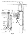
- a frame 121 according to the invention can have indirect lighting for a window 122 as a further accessory.
- open clamps 123 are provided which extend over the entire height of the frame or only a part thereof and at least one diffuser 124, e.g. Pyramidal disc, are covered.
- At least one luminous element 125 e.g. a conventional fluorescent tube, which can also extend over a large part of the height of the frame and illuminates the lens 124 when it is switched on.
- the lenses 124 are made of a light-scattering material or a transparent material with a scattering, e.g. ground, etched or profiled surface and have the task of casting a diffuse light on the window 122.
- the light is then reflected from the window glass into the room with the window and gives the impression that the light is passing through the window glass from the outside.
- This enables completely new lighting effects. For example, a uniform illumination of the room is achieved using a light source the size of the window.
- the conventional lighting sources and the associated electrical installations can be omitted. Since the artificial incidence of light occurs according to the incidence of daylight, the position of the furniture, e.g. Desks, only one direction of light to be observed. In addition, costs are saved by integrating the lighting into the frame.
- the light reflection in the region of the window 122 may d l rch application reflective glass sheets are improved. It is possible to use mirrored glass panes that are transparent to the outside in daylight, but reflect in the dark or when illuminated. Alternatively, it is possible to use the indirect lighting to illuminate a roller blind or blind wall 126 located behind the window or door, which wall is covered with a reflective layer instead of the glass panes.
- the roller blind or blind wall 126 can also be provided with a patterned image, for example a landscape image or an imitation of the image that resembles the natural view during the day.
- mini projectors in the side frame parts, which throw changing images onto the roller blind or blind wall 126.
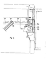
- the diffusing screen 124 and the luminous element 125 are preferably accommodated in a housing 127 which covers the chamber 123 towards the room side and can be telescopically inserted therein.
- the housing 127 is articulated, for example, at a lower end by means of pivot 128 to the frame 121 and can be pivoted by means of a handle 129, an upper housing part carrying the lens 124 being simultaneously guided telescopically in an upper wall of the chamber 123.
- This has the advantage that the effective width of the lens 124 and thus the effective light intensity can be adjusted continuously by pulling the housing 127 out of the chamber 123 to a greater or lesser extent.
- 15 shows the arrangement with the housing 127 fully extended, while FIG.
- the housing 17 shows the fully retracted position, which is desired, for example, when the window 122 is open.
- the housing 127 also serves to cover the lens 124 so that it is almost invisible from the room to be illuminated. If necessary, the housing can be pivoted in the direction of an arrow 130 (FIG. 15) until a line 131 is reached in order to allow access to the luminous element 125.
Landscapes
- Engineering & Computer Science (AREA)
- Civil Engineering (AREA)
- Structural Engineering (AREA)
- Specific Sealing Or Ventilating Devices For Doors And Windows (AREA)
- Wing Frames And Configurations (AREA)
Applications Claiming Priority (4)
| Application Number | Priority Date | Filing Date | Title |
|---|---|---|---|
| DE8321337U | 1983-07-23 | ||
| DE8321337 | 1983-07-23 | ||
| DE8406569U | 1984-03-02 | ||
| DE19848406569U DE8406569U1 (de) | 1984-03-02 | 1984-03-02 | Fenster oder tuer |
Publications (2)
| Publication Number | Publication Date |
|---|---|
| EP0132779A2 true EP0132779A2 (fr) | 1985-02-13 |
| EP0132779A3 EP0132779A3 (fr) | 1985-10-23 |
Family
ID=25949605
Family Applications (1)
| Application Number | Title | Priority Date | Filing Date |
|---|---|---|---|
| EP84108481A Withdrawn EP0132779A3 (fr) | 1983-07-23 | 1984-07-18 | Dormant de fenêtre |
Country Status (2)
| Country | Link |
|---|---|
| EP (1) | EP0132779A3 (fr) |
| DK (1) | DK355384A (fr) |
Cited By (8)
| Publication number | Priority date | Publication date | Assignee | Title |
|---|---|---|---|---|
| WO1988002805A1 (fr) * | 1986-10-14 | 1988-04-21 | John George Hamilton | Dispositif de ventilation |
| EP0719903A1 (fr) * | 1994-12-28 | 1996-07-03 | MONDIAL INFISSI S.r.l. | Fenêtre ou battant réalisé par la combinaison de matériaux tels que P.V.C. et aluminium ou similaires |
| WO2009050112A3 (fr) * | 2007-10-10 | 2009-09-24 | Klaus Heuchemer | Châssis dormant avec profilé interchangeable |
| CN105484639A (zh) * | 2015-08-14 | 2016-04-13 | 吉甫 | 一种多功能组合窗 |
| EP3034764A1 (fr) * | 2014-12-17 | 2016-06-22 | DORMA Deutschland GmbH | Installation de porte battante pliante |
| EP2161402B2 (fr) † | 2008-09-05 | 2016-10-26 | Südtirol Fenster S.r.l. | Encadrement de porte ou fenêtre préfabriqué avec une bordure isolante |
| EP2905412B1 (fr) * | 2014-02-07 | 2019-01-09 | Beck+Heun GmbH | Module complet de fenêtre, module d'aération intégré et élément d'isolation |
| CN115419351A (zh) * | 2022-09-28 | 2022-12-02 | 上海博乐之星节能科技有限公司 | 一种双扇联动的外开窗 |
Family Cites Families (8)
| Publication number | Priority date | Publication date | Assignee | Title |
|---|---|---|---|---|
| GB882862A (en) * | 1959-10-09 | 1961-11-22 | Poul Burup | Improvements in ventilators for space ventilation |
| DE6901155U (de) * | 1969-01-07 | 1969-07-03 | Josef Eberling | Fensterfertigbauelement |
| DE2302291A1 (de) * | 1973-01-18 | 1974-07-25 | Eppensteiner Weru Rolladen | Fertigelement fuer den einbau in wanddurchbrueche |
| DE2432746C3 (de) * | 1974-07-08 | 1980-08-21 | Bruegmann Frisoplast Gmbh, 4600 Dortmund | Fenster aus Kunststoff |
| JPS582848Y2 (ja) * | 1977-12-29 | 1983-01-18 | ワイケイケイ株式会社 | 折り戸の戸車装置 |
| DE2843435A1 (de) * | 1978-10-05 | 1980-04-24 | Reinhard Badewien | Insekten-schutz fuer fenster und tueren |
| DE8321337U1 (de) * | 1983-07-23 | 1983-11-24 | Schlitzberger, Hans, 3513 Staufenberg | Fensterzarge |
| DE8406569U1 (de) * | 1984-03-02 | 1984-06-14 | Schlitzberger, Hans, 3513 Staufenberg | Fenster oder tuer |
-
1984
- 1984-07-18 EP EP84108481A patent/EP0132779A3/fr not_active Withdrawn
- 1984-07-20 DK DK355384A patent/DK355384A/da not_active Application Discontinuation
Cited By (10)
| Publication number | Priority date | Publication date | Assignee | Title |
|---|---|---|---|---|
| WO1988002805A1 (fr) * | 1986-10-14 | 1988-04-21 | John George Hamilton | Dispositif de ventilation |
| EP0719903A1 (fr) * | 1994-12-28 | 1996-07-03 | MONDIAL INFISSI S.r.l. | Fenêtre ou battant réalisé par la combinaison de matériaux tels que P.V.C. et aluminium ou similaires |
| WO2009050112A3 (fr) * | 2007-10-10 | 2009-09-24 | Klaus Heuchemer | Châssis dormant avec profilé interchangeable |
| EP2161402B2 (fr) † | 2008-09-05 | 2016-10-26 | Südtirol Fenster S.r.l. | Encadrement de porte ou fenêtre préfabriqué avec une bordure isolante |
| EP2333219B1 (fr) | 2008-09-05 | 2018-12-19 | Südtirol Fenster S.r.l. | Encadrement de porte ou fenêtre préfabriqué avec une bordure isolante |
| EP2333219B2 (fr) † | 2008-09-05 | 2024-12-11 | Südtirol Fenster S.r.l. | Encadrement de porte ou fenêtre préfabriqué avec une bordure isolante |
| EP2905412B1 (fr) * | 2014-02-07 | 2019-01-09 | Beck+Heun GmbH | Module complet de fenêtre, module d'aération intégré et élément d'isolation |
| EP3034764A1 (fr) * | 2014-12-17 | 2016-06-22 | DORMA Deutschland GmbH | Installation de porte battante pliante |
| CN105484639A (zh) * | 2015-08-14 | 2016-04-13 | 吉甫 | 一种多功能组合窗 |
| CN115419351A (zh) * | 2022-09-28 | 2022-12-02 | 上海博乐之星节能科技有限公司 | 一种双扇联动的外开窗 |
Also Published As
| Publication number | Publication date |
|---|---|
| DK355384A (da) | 1985-01-24 |
| EP0132779A3 (fr) | 1985-10-23 |
| DK355384D0 (da) | 1984-07-20 |
Similar Documents
| Publication | Publication Date | Title |
|---|---|---|
| DE69231657T2 (de) | Doppellagige Verschattungseinrichtung | |
| EP0169918B1 (fr) | Fenêtre isolante thermiquement | |
| DE2607937A1 (de) | Fensterelement | |
| EP0932742B1 (fr) | Element de porte ou de fenetre | |
| DE3643233A1 (de) | Vorgefertigte fenster- und rolladenvorrichtung fuer haeuser u.dgl. | |
| EP0132779A2 (fr) | Dormant de fenêtre | |
| EP0093364A2 (fr) | Fenêtre composée insonorisante et calorifuge avec un dispositif d'aération | |
| DE9190032U1 (de) | Fenster mit Abschattungselement | |
| EP0367212B1 (fr) | Volet à rouleau se composant de lattes en forme de carter et de baguettes de jonction avec section transversale en forme de C | |
| DE69004825T2 (de) | Mobiles Verschlussmittel für Wandöffnung. | |
| DE69404247T2 (de) | Rolladenkasten | |
| AT394620B (de) | Vorrichtung zum abdecken einer gebaeudeoeffnung | |
| DE19820434C2 (de) | Parallel-Ausstellfenster-Anordnung mit Dichtsystem | |
| EP0140103A1 (fr) | Store | |
| EP1878866B1 (fr) | Elément pour intrados | |
| DE2541040C3 (de) | Schaukasten | |
| EP3832065B1 (fr) | Profilé de guidage pour une fenêtre ou une porte avec un caisson pour un volet roulant | |
| DE3227721A1 (de) | Rolladen fuer fenster und tueren an gebaeuden | |
| EP3848551B1 (fr) | Montants et traverses et procédé de montage d'une cassette doté d'un rideau pouvant être enroulé sur des montants et traverses | |
| DE8406569U1 (de) | Fenster oder tuer | |
| EP0690195A1 (fr) | Construction de cadre de fenêtre | |
| DE8321337U1 (de) | Fensterzarge | |
| DE8633840U1 (de) | Vorgefertigte Fenster- und Rolladenvorrichtung für Häuser u. dgl. | |
| EP1300542A1 (fr) | Volet roulant | |
| DE9203230U1 (de) | Bewegliche Abschlußvorrichtung |
Legal Events
| Date | Code | Title | Description |
|---|---|---|---|
| PUAI | Public reference made under article 153(3) epc to a published international application that has entered the european phase |
Free format text: ORIGINAL CODE: 0009012 |
|
| AK | Designated contracting states |
Designated state(s): AT BE CH DE FR GB IT LI LU NL |
|
| PUAL | Search report despatched |
Free format text: ORIGINAL CODE: 0009013 |
|
| AK | Designated contracting states |
Designated state(s): AT BE CH DE FR GB IT LI LU NL |
|
| 17P | Request for examination filed |
Effective date: 19860414 |
|
| 17Q | First examination report despatched |
Effective date: 19870515 |
|
| STAA | Information on the status of an ep patent application or granted ep patent |
Free format text: STATUS: THE APPLICATION IS DEEMED TO BE WITHDRAWN |
|
| 18D | Application deemed to be withdrawn |
Effective date: 19870926 |