EP0132780A1 - Ventilateur tangentiel avec une augmentation de vitesse de fluide, près des parois du raccord de pression - Google Patents
Ventilateur tangentiel avec une augmentation de vitesse de fluide, près des parois du raccord de pression Download PDFInfo
- Publication number
- EP0132780A1 EP0132780A1 EP84108482A EP84108482A EP0132780A1 EP 0132780 A1 EP0132780 A1 EP 0132780A1 EP 84108482 A EP84108482 A EP 84108482A EP 84108482 A EP84108482 A EP 84108482A EP 0132780 A1 EP0132780 A1 EP 0132780A1
- Authority
- EP
- European Patent Office
- Prior art keywords
- cross
- flow fan
- tab
- fan according
- fan
- Prior art date
- Legal status (The legal status is an assumption and is not a legal conclusion. Google has not performed a legal analysis and makes no representation as to the accuracy of the status listed.)
- Granted
Links
Images

Classifications
-
- F—MECHANICAL ENGINEERING; LIGHTING; HEATING; WEAPONS; BLASTING
- F04—POSITIVE - DISPLACEMENT MACHINES FOR LIQUIDS; PUMPS FOR LIQUIDS OR ELASTIC FLUIDS
- F04D—NON-POSITIVE-DISPLACEMENT PUMPS
- F04D17/00—Radial-flow pumps, e.g. centrifugal pumps; Helico-centrifugal pumps
- F04D17/02—Radial-flow pumps, e.g. centrifugal pumps; Helico-centrifugal pumps having non-centrifugal stages, e.g. centripetal
- F04D17/04—Radial-flow pumps, e.g. centrifugal pumps; Helico-centrifugal pumps having non-centrifugal stages, e.g. centripetal of transverse-flow type
-
- F—MECHANICAL ENGINEERING; LIGHTING; HEATING; WEAPONS; BLASTING
- F04—POSITIVE - DISPLACEMENT MACHINES FOR LIQUIDS; PUMPS FOR LIQUIDS OR ELASTIC FLUIDS
- F04D—NON-POSITIVE-DISPLACEMENT PUMPS
- F04D29/00—Details, component parts, or accessories
- F04D29/40—Casings; Connections of working fluid
- F04D29/42—Casings; Connections of working fluid for radial or helico-centrifugal pumps
- F04D29/44—Fluid-guiding means, e.g. diffusers
- F04D29/441—Fluid-guiding means, e.g. diffusers especially adapted for elastic fluid pumps
- F04D29/444—Bladed diffusers
-
- F—MECHANICAL ENGINEERING; LIGHTING; HEATING; WEAPONS; BLASTING
- F05—INDEXING SCHEMES RELATING TO ENGINES OR PUMPS IN VARIOUS SUBCLASSES OF CLASSES F01-F04
- F05D—INDEXING SCHEME FOR ASPECTS RELATING TO NON-POSITIVE-DISPLACEMENT MACHINES OR ENGINES, GAS-TURBINES OR JET-PROPULSION PLANTS
- F05D2250/00—Geometry
- F05D2250/50—Inlet or outlet
- F05D2250/52—Outlet
-
- Y—GENERAL TAGGING OF NEW TECHNOLOGICAL DEVELOPMENTS; GENERAL TAGGING OF CROSS-SECTIONAL TECHNOLOGIES SPANNING OVER SEVERAL SECTIONS OF THE IPC; TECHNICAL SUBJECTS COVERED BY FORMER USPC CROSS-REFERENCE ART COLLECTIONS [XRACs] AND DIGESTS
- Y10—TECHNICAL SUBJECTS COVERED BY FORMER USPC
- Y10S—TECHNICAL SUBJECTS COVERED BY FORMER USPC CROSS-REFERENCE ART COLLECTIONS [XRACs] AND DIGESTS
- Y10S415/00—Rotary kinetic fluid motors or pumps
- Y10S415/914—Device to control boundary layer
Definitions
- the invention relates to a cross-flow fan designed as a small or mini fan, consisting of a fan roller with blade edges running parallel to the axis of rotation, a spiral-shaped baffle plate, a one-part or multi-part surface, which transitions from the spiral shape in the area of the pressure chamber into a flat, curved or stepped surface Vortex formers and the sides of the fan rollers that completely or partially enclose the sides.
- Cross-flow fans whose fan roller has a diameter of 40-60 mm, for example, are referred to as small or mini fans.
- Such cross-flow fans are known as mass products and are used in large numbers, for example in household appliances, fan heaters, air conditioners, convectors, copiers, projectors, plug-in units for electrical and electronic devices and the like. The wide range of applications also shows that such fans have proven themselves in practice.
- the invention is therefore based on the object to improve the known cross-flow fan in such a way that a new measure, either alone or in conjunction with others, improves the flow of the peripheral zones and at the same time either completely prevents the whistle of the cross-flow fan or at least strongly dampens it without additional noise occurs in other operating areas of the fan.
- the cross-flow fan has a housing consisting of the side parts 1, the guide plate 2 and the vortex former 3, in which the fan roller 4 is rotatably mounted and is driven in the direction of the arrow 5 during operation.
- side parts, guide plate and vortex form an approximately rectangular air outlet opening from which the air in the direction of the arrow 6 should be conveyed as evenly as possible.
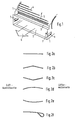
- the side parts are provided with the tabs 7 according to the invention.
- the tabs 7 have been produced by punching them out on three sides from the side parts and, for example, by bending them inwards at right angles to the side to which they are still connected to the side part.
- Such an embodiment of the invention has the additional advantage that with the help of the injector effect, a slight increase in the amount of air passed through is brought about. However, this effect only occurs if the opening 8 is below the tab.
- FIG. 2 shows six different embodiments of the tab 7.
- the tab according to FIG. 2a has a flat configuration.
- the tabs according to FIGS. 2b and 2c have a kinked configuration, the kink either pointing upwards or downwards.
- 2d and 2e show a curved shape of the tab, the Curvature can also be directed either upwards or downwards.
- 2f shows a further embodiment of the tab, which can be provided in all embodiments, namely the rounding 9 on the end of the tab 7 facing the fan roller.
- the tab 7 illustrates the position and arrangement of the tab 7 in the side part 1.
- the length of the tab is denoted by x and the distance of the tab base from the guide plate by y.
- the tab 7 can either be arranged at a right angle to the side part 1 or - as illustrated in FIG. 3 by the dashed layers - deviate from it by up to ⁇ 45 degrees.
- Characteristic line 10 shows diagrams which show the maximum sound pressure level L max as a function of the operating inconvenience in the case of a cross-flow fan (characteristic line 10) and in the case of a cross-flow fan with the tabs 7 according to the invention (characteristic curve 11).
- Characteristic line 11 shows that in the cross-flow fan according to the invention, in particular in free jet operation or small to medium throttling, the maximum sound pressure level is very much lower than the known cross-flow fan.
Landscapes
- Engineering & Computer Science (AREA)
- Mechanical Engineering (AREA)
- General Engineering & Computer Science (AREA)
- Structures Of Non-Positive Displacement Pumps (AREA)
Applications Claiming Priority (2)
| Application Number | Priority Date | Filing Date | Title |
|---|---|---|---|
| DE19833326650 DE3326650A1 (de) | 1983-07-23 | 1983-07-23 | Querstromluefter mit in den randzonen erhoehter luftaustrittsgeschwindigkeit |
| DE3326650 | 1983-07-23 |
Publications (2)
| Publication Number | Publication Date |
|---|---|
| EP0132780A1 true EP0132780A1 (fr) | 1985-02-13 |
| EP0132780B1 EP0132780B1 (fr) | 1986-11-05 |
Family
ID=6204784
Family Applications (1)
| Application Number | Title | Priority Date | Filing Date |
|---|---|---|---|
| EP84108482A Expired EP0132780B1 (fr) | 1983-07-23 | 1984-07-18 | Ventilateur tangentiel avec une augmentation de vitesse de fluide, près des parois du raccord de pression |
Country Status (4)
| Country | Link |
|---|---|
| US (1) | US4662818A (fr) |
| EP (1) | EP0132780B1 (fr) |
| AU (1) | AU3079784A (fr) |
| DE (2) | DE3326650A1 (fr) |
Cited By (1)
| Publication number | Priority date | Publication date | Assignee | Title |
|---|---|---|---|---|
| EP0915258A1 (fr) * | 1997-11-10 | 1999-05-12 | Carrier Corporation | Ventilateur à courant transversal avec stabilisateur de courant |
Families Citing this family (3)
| Publication number | Priority date | Publication date | Assignee | Title |
|---|---|---|---|---|
| US5314300A (en) * | 1992-01-13 | 1994-05-24 | Fasco Industries, Inc. | Noise control device for centrifugal blower |
| EP0999367B1 (fr) * | 1998-11-06 | 2003-02-12 | ALSTOM (Switzerland) Ltd | Conduit d'écoulement à discontinuité de section transversale |
| US7604965B2 (en) * | 2003-04-03 | 2009-10-20 | Fluidigm Corporation | Thermal reaction device and method for using the same |
Citations (1)
| Publication number | Priority date | Publication date | Assignee | Title |
|---|---|---|---|---|
| FR2266016A1 (fr) * | 1974-03-26 | 1975-10-24 | Int Standard Electric Corp |
Family Cites Families (12)
| Publication number | Priority date | Publication date | Assignee | Title |
|---|---|---|---|---|
| US1787655A (en) * | 1929-05-18 | 1931-01-06 | American Blower Corp | Apparatus and method of controlling fans |
| US2325221A (en) * | 1936-12-28 | 1943-07-27 | Walter H Bretzlaff | Segregated pressure fan |
| US2333017A (en) * | 1939-10-17 | 1943-10-26 | Quadrex Corp | Vacuum cleaner |
| US3002341A (en) * | 1957-12-31 | 1961-10-03 | Boeing Co | Jet engine noise suppression nozzles |
| DE1503591A1 (de) * | 1965-03-12 | 1970-04-09 | Prometheus Elek Sche Geraete U | Querstromgeblaese |
| US3832085A (en) * | 1972-10-04 | 1974-08-27 | Ford Motor Co | Automotive fan shroud |
| US3770081A (en) * | 1972-10-13 | 1973-11-06 | Line Inc M | Silencer for combustion engines |
| US3779341A (en) * | 1972-10-16 | 1973-12-18 | Modine Mfg Co | Noise suppressive fan shroud |
| US4014625A (en) * | 1973-08-20 | 1977-03-29 | Teruo Yamamoto | Transverse flow fan |
| DE2448362C2 (de) * | 1974-10-10 | 1983-01-20 | Standard Elektrik Lorenz Ag, 7000 Stuttgart | Als Klein- oder Kleinstlüfter ausgebildeter Querstromlüfter mit in den endscheibennahen Randzonen erhöhter Luftaustrittsgeschwindigkeit |
| GB1551362A (en) * | 1975-04-28 | 1979-08-30 | Komatsu Mfg Co Ltd | Radiator assembly |
| US4152094A (en) * | 1975-10-31 | 1979-05-01 | Hitachi, Ltd. | Axial fan |
-
1983
- 1983-07-23 DE DE19833326650 patent/DE3326650A1/de not_active Withdrawn
-
1984
- 1984-07-18 EP EP84108482A patent/EP0132780B1/fr not_active Expired
- 1984-07-18 AU AU30797/84A patent/AU3079784A/en not_active Abandoned
- 1984-07-18 DE DE8484108482T patent/DE3461213D1/de not_active Expired
-
1986
- 1986-01-15 US US06/819,472 patent/US4662818A/en not_active Expired - Fee Related
Patent Citations (1)
| Publication number | Priority date | Publication date | Assignee | Title |
|---|---|---|---|---|
| FR2266016A1 (fr) * | 1974-03-26 | 1975-10-24 | Int Standard Electric Corp |
Cited By (3)
| Publication number | Priority date | Publication date | Assignee | Title |
|---|---|---|---|---|
| EP0915258A1 (fr) * | 1997-11-10 | 1999-05-12 | Carrier Corporation | Ventilateur à courant transversal avec stabilisateur de courant |
| US5944481A (en) * | 1997-11-10 | 1999-08-31 | Carrier Corporation | Transverse fan with flow stabilizer |
| CN1092765C (zh) * | 1997-11-10 | 2002-10-16 | 运载器有限公司 | 具有流动稳定器的横向风机 |
Also Published As
| Publication number | Publication date |
|---|---|
| EP0132780B1 (fr) | 1986-11-05 |
| US4662818A (en) | 1987-05-05 |
| AU3079784A (en) | 1985-01-24 |
| DE3461213D1 (en) | 1986-12-11 |
| DE3326650A1 (de) | 1985-01-31 |
Similar Documents
| Publication | Publication Date | Title |
|---|---|---|
| DE4423762C2 (de) | Gebläse | |
| DE3882463T2 (de) | Diffusor für Zentrifugalverdichter. | |
| EP3255281B1 (fr) | Ventilateur avec aubes de diffuseur tandem | |
| DE19827449B4 (de) | Lüftereinheit für einen Luftreiniger | |
| DE102018211809A1 (de) | Gehäuse für einen Ventilator und Ventilator | |
| DE3608432A1 (de) | Mikrowellenherd | |
| DE3128625A1 (de) | Wirbelstromgeblaese | |
| DE4008012C2 (de) | Lüftungsanordnung für ein einen Gefrierraum und einen Kühlraum aufweisendes Kühlgerät | |
| EP0132793B1 (fr) | Ventilateur tangentiel | |
| DE3855315T2 (de) | Querstromgebläse | |
| EP0166158B1 (fr) | Ventilateur à courant transversal | |
| EP0132780B1 (fr) | Ventilateur tangentiel avec une augmentation de vitesse de fluide, près des parois du raccord de pression | |
| DE2708809C2 (fr) | ||
| EP0187906A2 (fr) | Dispositif de chauffage pour compartiments de passagers ou similaires, en particulier pour des omnibus | |
| DE2448362C2 (de) | Als Klein- oder Kleinstlüfter ausgebildeter Querstromlüfter mit in den endscheibennahen Randzonen erhöhter Luftaustrittsgeschwindigkeit | |
| DE3425450C2 (fr) | ||
| EP0177723A1 (fr) | Ventilateur radial | |
| EP0181481A1 (fr) | Ventilateur axial | |
| DE2644907A1 (de) | Radialgeblaese mit waermeaustauscher | |
| DE4219642C1 (de) | Ventilationsanordnung, die ein Gebläse enthält | |
| DE60101764T2 (de) | Fahrzeugklimaanlage | |
| DE4405630C2 (de) | Deckenauslaß | |
| DE4335165B4 (de) | Radiallüfter | |
| DE102016214467A1 (de) | Ventilatoreinheit und Anordnung mit mindestens zwei Ventilatoreinheiten | |
| DE3826588A1 (de) | Luftkuehler |
Legal Events
| Date | Code | Title | Description |
|---|---|---|---|
| PUAI | Public reference made under article 153(3) epc to a published international application that has entered the european phase |
Free format text: ORIGINAL CODE: 0009012 |
|
| AK | Designated contracting states |
Designated state(s): DE FR GB IT SE |
|
| 17P | Request for examination filed |
Effective date: 19850326 |
|
| GRAA | (expected) grant |
Free format text: ORIGINAL CODE: 0009210 |
|
| ITF | It: translation for a ep patent filed | ||
| AK | Designated contracting states |
Kind code of ref document: B1 Designated state(s): DE FR GB IT SE |
|
| REF | Corresponds to: |
Ref document number: 3461213 Country of ref document: DE Date of ref document: 19861211 |
|
| ET | Fr: translation filed | ||
| PLBE | No opposition filed within time limit |
Free format text: ORIGINAL CODE: 0009261 |
|
| STAA | Information on the status of an ep patent application or granted ep patent |
Free format text: STATUS: NO OPPOSITION FILED WITHIN TIME LIMIT |
|
| REG | Reference to a national code |
Ref country code: FR Ref legal event code: TP |
|
| 26N | No opposition filed | ||
| PG25 | Lapsed in a contracting state [announced via postgrant information from national office to epo] |
Ref country code: GB Effective date: 19880718 |
|
| PG25 | Lapsed in a contracting state [announced via postgrant information from national office to epo] |
Ref country code: SE Effective date: 19880719 |
|
| GBPC | Gb: european patent ceased through non-payment of renewal fee | ||
| PG25 | Lapsed in a contracting state [announced via postgrant information from national office to epo] |
Ref country code: FR Free format text: LAPSE BECAUSE OF NON-PAYMENT OF DUE FEES Effective date: 19890331 |
|
| PG25 | Lapsed in a contracting state [announced via postgrant information from national office to epo] |
Ref country code: DE Effective date: 19890401 |
|
| REG | Reference to a national code |
Ref country code: FR Ref legal event code: ST |
|
| EUG | Se: european patent has lapsed |
Ref document number: 84108482.5 Effective date: 19890510 |