EP0132832A2 - Circuit détecteur de mouvement d'image dans un signal de télévision interlacé - Google Patents
Circuit détecteur de mouvement d'image dans un signal de télévision interlacé Download PDFInfo
- Publication number
- EP0132832A2 EP0132832A2 EP84108737A EP84108737A EP0132832A2 EP 0132832 A2 EP0132832 A2 EP 0132832A2 EP 84108737 A EP84108737 A EP 84108737A EP 84108737 A EP84108737 A EP 84108737A EP 0132832 A2 EP0132832 A2 EP 0132832A2
- Authority
- EP
- European Patent Office
- Prior art keywords
- subtracter
- signal
- difference
- circuit
- obtaining
- Prior art date
- Legal status (The legal status is an assumption and is not a legal conclusion. Google has not performed a legal analysis and makes no representation as to the accuracy of the status listed.)
- Granted
Links
Images

Classifications
-
- H—ELECTRICITY
- H04—ELECTRIC COMMUNICATION TECHNIQUE
- H04N—PICTORIAL COMMUNICATION, e.g. TELEVISION
- H04N9/00—Details of colour television systems
-
- H—ELECTRICITY
- H04—ELECTRIC COMMUNICATION TECHNIQUE
- H04N—PICTORIAL COMMUNICATION, e.g. TELEVISION
- H04N5/00—Details of television systems
- H04N5/14—Picture signal circuitry for video frequency region
- H04N5/144—Movement detection
-
- G—PHYSICS
- G06—COMPUTING OR CALCULATING; COUNTING
- G06T—IMAGE DATA PROCESSING OR GENERATION, IN GENERAL
- G06T7/00—Image analysis
- G06T7/20—Analysis of motion
- G06T7/254—Analysis of motion involving subtraction of images
-
- H—ELECTRICITY
- H04—ELECTRIC COMMUNICATION TECHNIQUE
- H04N—PICTORIAL COMMUNICATION, e.g. TELEVISION
- H04N19/00—Methods or arrangements for coding, decoding, compressing or decompressing digital video signals
- H04N19/50—Methods or arrangements for coding, decoding, compressing or decompressing digital video signals using predictive coding
- H04N19/503—Methods or arrangements for coding, decoding, compressing or decompressing digital video signals using predictive coding involving temporal prediction
Definitions
- the present invention relates to a motion detecting circuit and particularly to a circuit for detecting motion of a picture in a television signal. Specifically, the present invention relates to a circuit for deriving information as to motion of an object included in an interlaced scanning television signal.
- the signal for interpolated scan lines is obtained from a signal in a preceding field.
- a high picture quality with no flicker can be displayed in the above-mentioned system. If the object moves, however, both the pictures in the field 1/60 seconds before and in the present field are displayed in an overlapped fashion, the edge of the moving portion of the picture becomes comb-like to deteriorate the picture quality.
- the circuit for detecting motion of an object in a television signal is used also in an inter-flame coding device, a recursive noise reducer, a luminance/ chrominance signal separation circuit besides the above-mentioned scan line interpolation circuit.
- the motion detecting circuit for an object in a television signal is arranged such that a frame memory is employed and a difference signal between a present picture element signal and a picture element signal on the same position two fields (one frame) before to thereby judge that the picture is a stationary one when the different signal is small, while a moving one when the different signal is large.
- a motion detecting circuit however, an object which is actually moving is sometimes misjudged to be a stationary one for the reason as described later in detail.
- a composite color television signal such as an NTSC color television signal, in which a color difference signal is modulated by a subcarrier and superimposed onto a luminance signal
- the phase of the subcarrier is different between frames and a modulated color signal as well as motion information leak into an inter-frame difference signal so as to make it difficult to get sufficiently correct motion information.
- the main object of the present invention is to provide a motion detecting circuit in which the motion of an object can be detected in spite of the motion speed of the object of the interlaced television signal.
- Another object of the present invention is to provide a circuit for accurately detecting the motion of an object of an interlaced composite color television signal.
- the motion detecting circuit comprises a pluraly of memories connected in series such that the sum of the capacities of the memories corresponds to at least three fiels of the television signal, an operation circuit for receiving a signal from an input/output terminal of the plurality of memories, the operation circuit including a subtracting circuit for obtaining an inter-frame difference signal, and a circuit for checking the inter-frame difference signals with respect to two succeeding fields so as to produce a signal indicating existence of movement when the inter-frame difference signal of either one of the two succeeding fields has a value which is equal to or larger than a predetermined value.
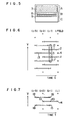
- Fig. 1 shows successively transmitted three fields of television pictures ((i-2), (i-1) and i field).
- the number of total scanning lines in each field of picture is 525/2 because of interlaced scanning, and in the drawing, a part of the scanning lines is shown by solid lines (1, 2, 3).
- sequentially scanned television pictures each including 525 scanning lines are formed from such interlace-scanned television pictures by doubling the scanning lines thereof.
- An interpolated scanning line 4 for this purpose is shown with a broken line.
- the signal for such an interpolated scanning line is interpolated with the scanning line 3 at the same position in the vertical direction (direction V) in the previous field (i-1) when the picture is a stationary one, while interpolated with the mean value of the adjacent upper and lower scanning lines 1 and 2 in the same field i when the picture is a moving one.
- Fig. 2 shows the manner of this interpolation with the axis representing time t and the vertical position V, in which the white dots represent interlaced scanning lines and the black dot an interpolated scanning line.
- the numerals 1, 2, 3 and 4 represent the same scanning lines as shown respectively in Fig. 1.
- the movement of an object is detected in such a manner that a present scanning line (1, 2) of field i is compared with a scanning line (1', 2') of field (i-2) at the same position two fields before so as to determine the picture as a stationary one when there is a small difference, while determine it as a moving one when there is a large difference therebetween.
- the signal of the interpolated scanning line 4 is obtained selectively from the scanning line 3 in the previous field (i-1) or from the mean value of the scanning lines 1 and 2 in the present field i.
- a picture as shown in Fig. 3 that is a black object 5 consisting of three scanning lines 5-1, 5-2, and 5-3, is moving up.
- Fig. 4 shows that the object is moving up at the rate of three scanning lines per field period.
- the picture of field i is regarded as a moving one in the regions A and C because there is a difference between the scanning line in the present field i and the corresponding scanning line in the previous frame so that the scanning line is interpolated with a mean value of the directly upper and lower scanning lines in the same field and adjacent to the scanning line to be interpolated as seen in the drawing, while in the region B, the picture is determined to be a stationary one because the respective values of the scanning lines in the i and the (i-2) fields are equal to each other so that the interpolation is attained with a corresponding scanning line in the (i-1) field.
- the scanning line of black picture in the (i-1) field is interpolated into the light background in the i field.
- Fig. 6 shows the arrangement of scanning lines of successive four fields with the axis of time t and the vertical position V, corresponding to the region B in Fig. 4.
- the interpolation mode of the interpolated scanning line 4 is such that not only the respective inter-frame difference signals 11 and 12 as to the scanning lines 1 and 2 in the present field but the inter-frame difference signal 13 as to the scanning line 3 in the same position in the previous field are considered so that when all the three inter-frame difference signals are small, the picture is determined to be a stationary one and thus the signal of the interpolated scanning line 4 is interpolated from the scanning line 3 in the previous field (i-1), while in the other case the picture is determined to be a moving one and the interpolation is performed with the mean value of the upper and lower scanning lines 1 and 2 in the same field i and adjacent to the interpolated line.
- the picture is determined to be a moving one because the inter-frame difference signal 13 is large while both the inter-frame difference signals 11 and 12 are small and the interpolation scanning line 4 is interpolated with the mean value of the scanning lines 1 and 2.
- the interpolation scanning line 4 is interpolated with the mean value of the scanning lines 1 and 2.
- the picture signals of i and (i-1) fields are used to obtain the signal of the interpolated scanning line in the i field.
- the signals of the (i-1), (i-2), and (i-3) fields are used for the purpose of detection as to whether the picture is a moving one or not in order to changeover the interpolation processing mode. For this, there is a large offset in time between the judgement as to whether the picture is a stationary one or a moving one and the interpolation processing, resulting in a case where proper processing can not be performed to cope with the result of detection.
- the signals in the (i-2) and (i-1) fields are used for the interpolation processing and the signals in the (i-3) and i fields adjacent to the (i-1) field are used so that the time offset between the stationariness/movement judgement and the interpolation processing using the results of the judgement is so small that proper processing can be effected to cope with the results of the judgement. That is, in Fig.
- the maximum time interval is two field-periods so as to minimize the time offset between the interpolation operation and the stationariness/ movement judgement.
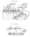
- Fig. 8 shows the arrangement of an embodiment of a scanning line interpolation circuit using the movement detecting circuit according to the present invention.
- the part encircled by a broken line is the circuit for detecting the movement of an object.
- the signal for the interpolation scanning line 20 is obtained, on the basis of the principle as described above as to Fig. 7, by properly changing the mixture ratio of the mean value of the scanning lines 14-and 17 to the mean value of the scanning lines 15 and 16 by means of a movement coefficient k (0 S k S 1) obtained by the results of stationariness/movement judgement.
- three field memories 21, 23, and 24 each having a capacity of 262H (H represents the period of one horizontal scanning line) and line memories 22 and 25 each having a capacity of 1H are connected in series. That is, a plurality of memories including three field momories are connected in series.
- a luminance signal (it may be a monochromatic television signal or a low frequency component of a color television signal) is applied to the input terminal. Assuming that the television signal 14 applied to the input terminal is the signal of the scanning line 14 in Fig. 7, the respective outputs of the memories 21, 22, 23, 24, and 25 are the signals of the scanning lines 15, 16, 17, 18, and 19 in Fig. 7, as indicated with the same reference numerals in Fig. 8.
- a subtracter 33 produces an inter-frame difference signal (17)-(14) as to the scanning lines 14 and 17
- a subtracter 35 produces an inter-frame difference signal as to the scanning lines 15 and 18
- a subtracter 37 produces an inter-frame difference signal as to the scanning lines 16 and 19, respectively.
- Absolute circuits 34, 36, and 38 respectively indicate with absolute values the inter-frame difference signals produced by the subtracters 33, 35, and 37.
- An adder 39 adds the respective outputs of the absolute circuits 34, 36, and 38.
- a coefficient conversion circuit 40 is for changing the value of the coefficient k in accordance with the output of the adder 39. The movement coefficient k controles construction of interpolated scanning line in such a manner as described hereunder.
- a mean value of the scanning lines 14 and 17 is formed by an adder 28 and a coefficient circuit 29 for multiplying by a coefficient of 1/2 and a mean value of the scanning lines 15 and 16 is formed by an adder 26 and a coefficient circuit 27 for multiplying by a coefficient of 1/2.
- the each output of the coefficient circuits 29 and 27 is multiplied by k and (1-k) respectively by multiplying circuits 31 and 30 and the respective outputs of the multiplying circuits 31 and 30 are added by an adder 32 so as to obtain an interpolation scanning line signal corresponding to the movement of the picture.
- the signal V 20 of the interpolation scanning line 20 is expressed by the following equation: where V 14' V 15' V 16' and V 17 represent the respective signal of the scanning lines 14, 15, 16 and 17.
- the coefficient k is changed by the motion detecting circuit so as to approach 1 in a stationary picture portion while to approach 0 in a moving picture portion.
- the coefficient k can take various values between 1 and 0, sometime it is restricted to two values, 1 and 0 in order to omit the multiplying circuits 30 and 31 to simplify the arrangement of the circuit. In this case, not only the multiplying circuits 30 and 31 can be omitted but the adder 32 can be replaced by a switch. Further, the adder 39 and the coefficient conversion circuit 40 may be omitted by logically adding the respective results of stationariness/movement judgement as to the absolute value signals of the inter-frame difference signals (respective output signals of the absolute circuits 34, 36, and 38).
- the motion information as to an interlaced picture is extracted from an inter-frame difference signal between two successive fields, the deterioration in picture quality due to misprocessing on the basis of misjudgement of a moving picture portion as a stationary picture portion so that a proper scanning line interpolation processing can be performed without occurring deterioration in picture quality.
- Fig. 9 is a diagram showing the arrangement of another embodiment of the motion detecting circuit according to the present invention.
- the motion detecting circuit shown in Fig. 8 by encircling with a broken line is effective in the case where the input television signal is a monochromatic one or a composite color television signal including no chrominance signal.
- a composite color television signal as an NTSC television signal in which a color difference signal is modulated with a subcarrier and superimposed onto a luminance signal, only the motion information but a modulated chrominance signal may enter the inter-frame difference signal so that correct motion information can not be obtained because the subcarrier which modulates the color difference signal is different in phase between frames. Accordingly, in the embodiment of Fig.
- a composite color television signal applied to an input terminal 41 is divided into a low frequency component having no carrierred chrominance component and a modulated chrominance signal component by a low pass filter (L PF ) and a band pass filter (BPF) respectively, and the low frequency component is applied to a first motion detecting circuit 45 which is similar to the motion detecting circuit described above with respect to Fig. 8.
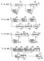
- the modulated chrominance signal component is applied to a second motion detecting circuit 44, various embodiments of which are illustrated in Figs. 10A, 10B, 10C, and 10D.
- the output of the second motion detecting circuit 44 is applied to an adder 46 through an absolute circuit 47 and added to the output of the first motion detecting circuit 45 in the adder 46.
- the output of the adder 46 is produced through an output terminal 42 as the general motion information as to a picture.
- the second motion detecting circuit 44 includes a momory having a capacity capable of storing at least three fields of pictures, whereby the motion information as to a picture can be extracted in accordance with the value of an inter-frame difference signal as to inter-field difference signal (or absolute value signals thereof) between two fields in which the respective subcarriers are in phase. That is, in an NTSC color television signal, the polarity of the subcarrier is inverted every horizontal scanning period H, so that no difference signal appears ' in a stationary picture portion except at an edge portion at which picture changes abruptly, when a difference is to be obtained between a present signal and a previous field signal delayed 262H.
- this inter-field difference signal may include the picture motion information as well as a high frequency vertical component of a stationary picture. If an inter-frame difference signal is calculated from the inter-field difference signal, the high frequency vertical component of a stationary picture can be cancelled and correct motion information can be derived.
- a composite color television signal applied to an input terminal 51 is subtracted in a subtracter circuit 55 from the output signal of a field memory 53 having a capacity of 262H. That is, the subtracter circuit 55 produces an inter-field difference signal.
- the polarity of the modulated chrominance signal is inverted every horizontal period H, and the present scanning line and the scanning line delayed 262H are the same in polarity.
- the output of the subtracter 55 is zero in a stationary picture portion where no abrupt level change in the vertical direction appears, while a significant difference signal appears at the output of the subtracter 55 in a moving picture and in a stationary picture portion where an abrupt change in the vertical direction exists.
- This difference signal is delayed in a frame memory 54 and an inter-frame difference signal between the respective outputs of the subtracter circuit 55 and the frame memory 54 is calculated in a subtracter circuit 56. Being the same in every frame, the component of the vertical level change of a stationary picture is cancelled in the inter-frame difference signal, so that only the moving picture component appears at an output terminal 52.
- the motion detecting circuit of Fig. 10B is for obtaining the inter-frame difference signal as to an inter-field difference signal, similarly to the circuit of Fig. 10A.
- the circuit of Fig. 10B includes field memories 58, 59, and 60 connected in cascade to an input terminal 51 and having capacities of 262H, 263H, and 262H respectively, a subtracter circuit 61 for obtaining the difference signal between the input and output of the field memory 58, a subtracter circuit 62 for obtaining the difference signal between the respective outputs of the subtracter circuit 61 and the field momory 59, an adder 63 for adding the respective outputs of the subtracter circuit 62 and the field memory 60.
- the circuit of Fig. 10C is a modification of the circuit of Fig. 10A in which an absolute circuit 57 is added to the output portion of the subtracter 55.
- an absolute value of the inter-field difference signal is calculated and if the thus obtained absolute values are equal between frames, it is judged that there exists no picture movement. In this manner, such a misjudge that a stationary picture is misjudged as a moving picture at a portion of the stationary picture where an abrupt color change exists in the vertical direction can be prevented from occurring.
- the circuit of Fig. 10D is a modification of the circuit of Fig. 10B, and includes field memories 58, 59, and 60 connected in cascade to an input terminal 51, a subtracter circuit 61 for obtaining the difference signal between the input and output of the field memory 58, a subtracter circuit 65 for obtaining the difference signal between the input and output of the field memory 60, absolute circuits 64 and 66 connected to the respective outputs of the subtracter circuits 61 and 65, and a subtracter circuit 67 for obtaining the difference between the respective outputs of the absolute circuits 64 and 66 so as to obtain an inter-frame difference signal as to the inter-field difference signal.
- the function of the absolute circuits 64 and 66 are the same as the absolute circuit 57 of Fig. 10C.
- the motion detecting circuit of each of Figs. 10A, 10B, 10C and 10D is illustrated in the case where the motion detecting circuit is connected to the first motion detecting circuit 45 of Fig. 9, it can detect the picture motion independently of the first motion detecting circuit 45 if deterioration in accuracy is allowed at an extent.
Landscapes
- Engineering & Computer Science (AREA)
- Multimedia (AREA)
- Signal Processing (AREA)
- Computer Vision & Pattern Recognition (AREA)
- Physics & Mathematics (AREA)
- General Physics & Mathematics (AREA)
- Theoretical Computer Science (AREA)
- Television Systems (AREA)
- Color Television Systems (AREA)
- Processing Of Color Television Signals (AREA)
Applications Claiming Priority (4)
| Application Number | Priority Date | Filing Date | Title |
|---|---|---|---|
| JP134326/83 | 1983-07-25 | ||
| JP58134326A JPS6027287A (ja) | 1983-07-25 | 1983-07-25 | 動き検出回路 |
| JP164988/83 | 1983-09-09 | ||
| JP58164988A JPS6057792A (ja) | 1983-09-09 | 1983-09-09 | 動き検出回路 |
Publications (3)
| Publication Number | Publication Date |
|---|---|
| EP0132832A2 true EP0132832A2 (fr) | 1985-02-13 |
| EP0132832A3 EP0132832A3 (en) | 1985-04-03 |
| EP0132832B1 EP0132832B1 (fr) | 1987-11-04 |
Family
ID=26468457
Family Applications (1)
| Application Number | Title | Priority Date | Filing Date |
|---|---|---|---|
| EP84108737A Expired EP0132832B1 (fr) | 1983-07-25 | 1984-07-24 | Circuit détecteur de mouvement d'image dans un signal de télévision interlacé |
Country Status (5)
| Country | Link |
|---|---|
| US (1) | US4626891A (fr) |
| EP (1) | EP0132832B1 (fr) |
| KR (1) | KR910009880B1 (fr) |
| CA (1) | CA1222049A (fr) |
| DE (1) | DE3467281D1 (fr) |
Cited By (9)
| Publication number | Priority date | Publication date | Assignee | Title |
|---|---|---|---|---|
| FR2599204A1 (fr) * | 1986-05-23 | 1987-11-27 | Rca Corp | Processeur de signaux video a balayage progressif |
| FR2604049A1 (fr) * | 1986-09-12 | 1988-03-18 | Labo Electronique Physique | Procede de conversion de signaux video entrelaces en signaux video non entrelaces et convertisseur de signaux video pour la mise en oeuvre de ce procede |
| EP0208990A3 (fr) * | 1985-07-12 | 1988-10-19 | Hitachi, Ltd. | Circuit de détection de mouvement pour des signaux de télévision |
| EP0241854A3 (en) * | 1986-04-09 | 1989-11-23 | Hitachi, Ltd. | Video signal processing circuit of motion adaptive type |
| EP0263375A3 (en) * | 1986-09-30 | 1990-04-11 | Nippon Hoso Kyokai | A method and apparatus for detecting the motion of image in a television signal |
| EP0348207A3 (fr) * | 1988-06-24 | 1991-07-24 | Matsushita Electric Industrial Co., Ltd. | Appareil de détection de vecteur mouvement d'une image |
| EP0376330A3 (fr) * | 1988-12-28 | 1992-05-13 | Nec Home Electronics, Ltd. | Circuit et méthode de détection de mouvement et de séparation Y/C pour la détection de mouvement dans une image d'affichage télévision |
| WO1992021201A1 (fr) * | 1991-05-24 | 1992-11-26 | British Broadcasting Corporation | Traitement d'images video |
| US7652012B2 (en) | 2002-02-08 | 2010-01-26 | Glaxo Group Limited | 2-(R)-(4-fluoro-2-methyl-phenyl)-4-(S)-((8aS)-6-oxo-hexahydro-pyrrolo[1,2-a]-pyrazin-2-yl)-piperidine-1-carboxylic acid [1-(R)-3,5-bis-trifluoromethyl-phenyl)-ethyl]-methylamide maleate and pharmaceutical compositions thereof |
Families Citing this family (35)
| Publication number | Priority date | Publication date | Assignee | Title |
|---|---|---|---|---|
| JPS59171387A (ja) * | 1983-03-18 | 1984-09-27 | Hitachi Ltd | テレビジヨン信号の構成方法 |
| US4823184A (en) * | 1984-04-09 | 1989-04-18 | Corporate Communications Consultants, Inc. | Color correction system and method with scene-change detection |
| DE3502315A1 (de) * | 1985-01-24 | 1986-07-24 | Siemens AG, 1000 Berlin und 8000 München | Verfahren zur bildfehlerkorrektur |
| DE3502317A1 (de) * | 1985-01-24 | 1986-07-24 | Siemens AG, 1000 Berlin und 8000 München | Verfahren zur bildfehlerkorrektur |
| DE3526596C2 (de) * | 1985-07-25 | 1994-05-05 | Nokia Deutschland Gmbh | Schaltungsanordnung zur Detektion einer Bewegung in einem Fernsehbild |
| US4739390A (en) * | 1985-08-30 | 1988-04-19 | Hitachi, Ltd. | Television signal processing circuit |
| US4775888A (en) * | 1985-11-22 | 1988-10-04 | Hitachi, Ltd. | Motion detector for chrominance signal in TV receiver |
| JPH0744689B2 (ja) * | 1985-11-22 | 1995-05-15 | 株式会社日立製作所 | 動き検出回路 |
| JP2718668B2 (ja) * | 1986-10-06 | 1998-02-25 | 株式会社日立製作所 | 動き検出回路 |
| JP2579930B2 (ja) * | 1987-03-17 | 1997-02-12 | 株式会社東芝 | 複合信号分離回路 |
| US4893182A (en) * | 1988-03-18 | 1990-01-09 | Micronyx, Inc. | Video tracking and display system |
| US5101354A (en) * | 1988-04-18 | 1992-03-31 | Brunswick Bowling & Billards Corporation | Multi-lane bowling system with remote operator control |
| US5255185A (en) * | 1988-04-18 | 1993-10-19 | Brunswick Bowling & Billiards Corp. | Bowling center video display system |
| DE68919431T2 (de) * | 1988-04-30 | 1995-03-30 | Victor Company Of Japan | Schaltung zur Verbesserung der Bildqualität. |
| JP2634632B2 (ja) * | 1988-06-15 | 1997-07-30 | 株式会社日立製作所 | 動き検出回路 |
| FR2633137B1 (fr) * | 1988-06-21 | 1990-11-09 | Labo Electronique Physique | Systeme d'emission et reception de television a haute definition a estimateur de vitesses ameliore et a debit de donnees reduit |
| JPH0229178A (ja) * | 1988-07-19 | 1990-01-31 | Sony Corp | 映像信号処理回路 |
| US4953032A (en) * | 1988-11-30 | 1990-08-28 | Hitachi, Ltd. | Motion signal generating circuit for use in a television receiver |
| JP2732650B2 (ja) * | 1989-02-28 | 1998-03-30 | 株式会社東芝 | 垂直エッジ検出回路 |
| US5027201A (en) * | 1989-12-21 | 1991-06-25 | Rca Licensing Corporation | Motion detection apparatus as for an interlace to non-interlace scan converter |
| KR930009881B1 (ko) * | 1989-12-22 | 1993-10-12 | 삼성전자 주식회사 | 패턴검출 및 운동량 검출에 의한 칼라텔레비젼 신호의 엔코딩회로 |
| US5081532A (en) * | 1990-08-30 | 1992-01-14 | Zenith Electronics Corporation | Adaptive progressive scan converter |
| JPH04145777A (ja) * | 1990-10-05 | 1992-05-19 | Sharp Corp | 動きベクトル検出装置 |
| US8352400B2 (en) | 1991-12-23 | 2013-01-08 | Hoffberg Steven M | Adaptive pattern recognition based controller apparatus and method and human-factored interface therefore |
| US10361802B1 (en) | 1999-02-01 | 2019-07-23 | Blanding Hovenweep, Llc | Adaptive pattern recognition based control system and method |
| US5594813A (en) * | 1992-02-19 | 1997-01-14 | Integrated Information Technology, Inc. | Programmable architecture and methods for motion estimation |
| JPH0937298A (ja) * | 1995-07-13 | 1997-02-07 | Philips Japan Ltd | 順次走査変換装置 |
| US6340990B1 (en) * | 1998-03-31 | 2002-01-22 | Applied Intelligent Systems Inc. | System for deinterlacing television signals from camera video or film |
| US7966078B2 (en) | 1999-02-01 | 2011-06-21 | Steven Hoffberg | Network media appliance system and method |
| JP4419210B2 (ja) * | 1999-06-01 | 2010-02-24 | ソニー株式会社 | 画像処理装置および方法、並びに記録媒体 |
| CN1606758A (zh) * | 2000-08-31 | 2005-04-13 | 雷泰克公司 | 传感器和成像系统 |
| US7321699B2 (en) | 2002-09-06 | 2008-01-22 | Rytec Corporation | Signal intensity range transformation apparatus and method |
| CN1279756C (zh) * | 2003-05-23 | 2006-10-11 | 华亚微电子(上海)有限公司 | 应用场景静止检测的视频信号自适应递归降噪方法 |
| TWI220366B (en) * | 2003-08-11 | 2004-08-11 | Mediatek Inc | Scalable video format conversion system |
| SG188546A1 (en) * | 2010-10-20 | 2013-04-30 | Agency Science Tech & Res | A method, an apparatus and a computer program product for deinterlacing an image having a plurality of pixels |
Family Cites Families (7)
| Publication number | Priority date | Publication date | Assignee | Title |
|---|---|---|---|---|
| US3632865A (en) * | 1969-12-23 | 1972-01-04 | Bell Telephone Labor Inc | Predictive video encoding using measured subject velocity |
| DE2432399C3 (de) * | 1974-07-05 | 1980-07-31 | Standard Elektrik Lorenz Ag, 7000 Stuttgart | System zur digitalen Übertragung von Bildsignalen mittels Differenz-Pulscodemodulation (DPCM) |
| US4218703A (en) * | 1979-03-16 | 1980-08-19 | Bell Telephone Laboratories, Incorporated | Technique for estimation of displacement and/or velocity of objects in video scenes |
| GB2045574B (en) * | 1979-03-22 | 1983-04-20 | Quantel Ltd | Video movement detection |
| JPS6360960B2 (fr) * | 1980-10-22 | 1988-11-25 | ||
| US4494140A (en) * | 1981-01-22 | 1985-01-15 | Micro Consultants Limited | T.V. apparatus for movement control |
| JPS58117788A (ja) * | 1982-01-06 | 1983-07-13 | Hitachi Ltd | カラ−テレビジヨン信号処理回路 |
-
1984
- 1984-07-20 KR KR1019840004290A patent/KR910009880B1/ko not_active Expired
- 1984-07-23 US US06/633,273 patent/US4626891A/en not_active Expired - Lifetime
- 1984-07-24 CA CA000459529A patent/CA1222049A/fr not_active Expired
- 1984-07-24 EP EP84108737A patent/EP0132832B1/fr not_active Expired
- 1984-07-24 DE DE8484108737T patent/DE3467281D1/de not_active Expired
Cited By (12)
| Publication number | Priority date | Publication date | Assignee | Title |
|---|---|---|---|---|
| EP0208990A3 (fr) * | 1985-07-12 | 1988-10-19 | Hitachi, Ltd. | Circuit de détection de mouvement pour des signaux de télévision |
| EP0241854A3 (en) * | 1986-04-09 | 1989-11-23 | Hitachi, Ltd. | Video signal processing circuit of motion adaptive type |
| FR2599204A1 (fr) * | 1986-05-23 | 1987-11-27 | Rca Corp | Processeur de signaux video a balayage progressif |
| FR2604049A1 (fr) * | 1986-09-12 | 1988-03-18 | Labo Electronique Physique | Procede de conversion de signaux video entrelaces en signaux video non entrelaces et convertisseur de signaux video pour la mise en oeuvre de ce procede |
| EP0263375A3 (en) * | 1986-09-30 | 1990-04-11 | Nippon Hoso Kyokai | A method and apparatus for detecting the motion of image in a television signal |
| EP0348207A3 (fr) * | 1988-06-24 | 1991-07-24 | Matsushita Electric Industrial Co., Ltd. | Appareil de détection de vecteur mouvement d'une image |
| US5111511A (en) * | 1988-06-24 | 1992-05-05 | Matsushita Electric Industrial Co., Ltd. | Image motion vector detecting apparatus |
| EP0376330A3 (fr) * | 1988-12-28 | 1992-05-13 | Nec Home Electronics, Ltd. | Circuit et méthode de détection de mouvement et de séparation Y/C pour la détection de mouvement dans une image d'affichage télévision |
| WO1992021201A1 (fr) * | 1991-05-24 | 1992-11-26 | British Broadcasting Corporation | Traitement d'images video |
| AU660020B2 (en) * | 1991-05-24 | 1995-06-08 | British Broadcasting Corporation, The | Video image processing |
| US6011596A (en) * | 1991-05-24 | 2000-01-04 | British Broadcasting | Video image motion compensation using an algorithm involving at least two fields |
| US7652012B2 (en) | 2002-02-08 | 2010-01-26 | Glaxo Group Limited | 2-(R)-(4-fluoro-2-methyl-phenyl)-4-(S)-((8aS)-6-oxo-hexahydro-pyrrolo[1,2-a]-pyrazin-2-yl)-piperidine-1-carboxylic acid [1-(R)-3,5-bis-trifluoromethyl-phenyl)-ethyl]-methylamide maleate and pharmaceutical compositions thereof |
Also Published As
| Publication number | Publication date |
|---|---|
| EP0132832B1 (fr) | 1987-11-04 |
| CA1222049A (fr) | 1987-05-19 |
| US4626891A (en) | 1986-12-02 |
| DE3467281D1 (en) | 1987-12-10 |
| KR910009880B1 (ko) | 1991-12-03 |
| EP0132832A3 (en) | 1985-04-03 |
| KR850000862A (ko) | 1985-03-09 |
Similar Documents
| Publication | Publication Date | Title |
|---|---|---|
| US4626891A (en) | Motion detecting circuit utilizing inter-frame difference signals of successive fields | |
| CA2245940C (fr) | Processeur a signaux d'imagerie servant a detecter les images en double | |
| KR920001006B1 (ko) | Tv방식변환장치 | |
| US4811092A (en) | Movement detector for composite color television signals | |
| JPS6390987A (ja) | 動き検出回路 | |
| JPH04234276A (ja) | 動き検出方法 | |
| KR100254960B1 (ko) | 움직임 검출 회로 | |
| US4688084A (en) | Movement detection circuit for television signals | |
| JPS62111586A (ja) | 動き適応型信号処理回路 | |
| EP0364967B1 (fr) | Circuit de séparation des signaux luminance/chrominance pour un signal de télévision en couleurs PAL | |
| JP2600884B2 (ja) | テレビジョン受像機 | |
| JPS6225587A (ja) | 動きベクトル検出回路 | |
| JPH082101B2 (ja) | 動き適応走査線補間回路 | |
| JP3683990B2 (ja) | 動きベクトル検出装置及び方法 | |
| JPS6065681A (ja) | 画像の動き情報検出方式 | |
| JP2519526B2 (ja) | 信号処理装置 | |
| JP3235744B2 (ja) | 画像判別装置及び画像判別方法 | |
| KR930000982B1 (ko) | 텔레비젼 수상기에 있어서 고립점 제거가 부가된 움직임 검출회로 | |
| JPH0530391A (ja) | 動き検出回路 | |
| JPH0724423B2 (ja) | 動き適応型輝度信号色信号分離装置及び動き検出回路 | |
| JPH05300541A (ja) | 動き検出回路 | |
| JPS62172881A (ja) | 映像信号エンコ−ド方式 | |
| JPS62183283A (ja) | テレビジヨン信号処理装置 | |
| JPH06245141A (ja) | テレビジョン回路 | |
| JPH05219531A (ja) | 動き信号発生回路 |
Legal Events
| Date | Code | Title | Description |
|---|---|---|---|
| PUAI | Public reference made under article 153(3) epc to a published international application that has entered the european phase |
Free format text: ORIGINAL CODE: 0009012 |
|
| PUAL | Search report despatched |
Free format text: ORIGINAL CODE: 0009013 |
|
| 17P | Request for examination filed |
Effective date: 19840724 |
|
| AK | Designated contracting states |
Designated state(s): DE FR GB |
|
| AK | Designated contracting states |
Designated state(s): DE FR GB |
|
| 17Q | First examination report despatched |
Effective date: 19860602 |
|
| GRAA | (expected) grant |
Free format text: ORIGINAL CODE: 0009210 |
|
| AK | Designated contracting states |
Kind code of ref document: B1 Designated state(s): DE FR GB |
|
| REF | Corresponds to: |
Ref document number: 3467281 Country of ref document: DE Date of ref document: 19871210 |
|
| ET | Fr: translation filed | ||
| PLBE | No opposition filed within time limit |
Free format text: ORIGINAL CODE: 0009261 |
|
| STAA | Information on the status of an ep patent application or granted ep patent |
Free format text: STATUS: NO OPPOSITION FILED WITHIN TIME LIMIT |
|
| 26N | No opposition filed | ||
| PGFP | Annual fee paid to national office [announced via postgrant information from national office to epo] |
Ref country code: FR Payment date: 19990519 Year of fee payment: 16 |
|
| PGFP | Annual fee paid to national office [announced via postgrant information from national office to epo] |
Ref country code: GB Payment date: 19990625 Year of fee payment: 16 |
|
| PGFP | Annual fee paid to national office [announced via postgrant information from national office to epo] |
Ref country code: DE Payment date: 19990827 Year of fee payment: 16 |
|
| PG25 | Lapsed in a contracting state [announced via postgrant information from national office to epo] |
Ref country code: GB Free format text: LAPSE BECAUSE OF NON-PAYMENT OF DUE FEES Effective date: 20000724 |
|
| GBPC | Gb: european patent ceased through non-payment of renewal fee |
Effective date: 20000724 |
|
| PG25 | Lapsed in a contracting state [announced via postgrant information from national office to epo] |
Ref country code: FR Free format text: LAPSE BECAUSE OF NON-PAYMENT OF DUE FEES Effective date: 20010330 |
|
| REG | Reference to a national code |
Ref country code: FR Ref legal event code: ST |
|
| PG25 | Lapsed in a contracting state [announced via postgrant information from national office to epo] |
Ref country code: DE Free format text: LAPSE BECAUSE OF NON-PAYMENT OF DUE FEES Effective date: 20010501 |