EP0132969B1 - Appareils détecteurs de fumée - Google Patents
Appareils détecteurs de fumée Download PDFInfo
- Publication number
- EP0132969B1 EP0132969B1 EP19840304549 EP84304549A EP0132969B1 EP 0132969 B1 EP0132969 B1 EP 0132969B1 EP 19840304549 EP19840304549 EP 19840304549 EP 84304549 A EP84304549 A EP 84304549A EP 0132969 B1 EP0132969 B1 EP 0132969B1
- Authority
- EP
- European Patent Office
- Prior art keywords
- sampling
- pipe
- smoke
- base
- smoke detection
- Prior art date
- Legal status (The legal status is an assumption and is not a legal conclusion. Google has not performed a legal analysis and makes no representation as to the accuracy of the status listed.)
- Expired
Links
Images


Classifications
-
- G—PHYSICS
- G08—SIGNALLING
- G08B—SIGNALLING SYSTEMS, e.g. PERSONAL CALLING SYSTEMS; ORDER TELEGRAPHS; ALARM SYSTEMS
- G08B17/00—Fire alarms; Alarms responsive to explosion
- G08B17/06—Electric actuation of the alarm, e.g. using a thermally-operated switch
Definitions
- This invention relates to smoke detection apparatus.
- Said smoke transport system may take the form of a pipe or network thereof, configured to draw a continuous small sample of air from the areas within which fire detection is required. The aggregate of all said areas constitutes one fire zone. Said continuous sample of air from said zone is drawn by means of a fan, downstream from said sampling chamber. Each location where an opening is made to allow the passage of air into said smoke transport system, constitutes a sampling point.
- the atmosphere may be relatively clear of smoke depending upon the use of the premises.
- Dormitories in a school, or partitioned offce blocks for example would have a relatively clear atmosphere.
- the kitchen in each House Master's quarters of that school could have a smokey atmosphere at cooking times, while bathrooms would regularly become steamed.
- certain areas of a factory such as a main workshop may have a polluted atmosphere whereas other areas in the factor are relatively clear.
- the use of sensitive smoke detection apparatus in said areas would certainly lead to false alarms.
- EP-A-0040342 discloses the concept of controlling sampling apertures in a smoke detection system by providing manually adjustable devices.
- US-A-4,241,282 discloses a radiation sensitive smoke detector wherein a bimetallic element is provided in the radiation region to compensate for decrease in the sensitivity of the detector to smoke with temperature increase.
- US-A-4,170,189 discloses a heat sensitive assembly incorporating eutectic metal.
- US-A-3,765,842 discloses a switchable air sampling system for withdrawing air samples sequentially from a supervised space and testing them for carbon monoxide.
- the most effective, economical and versatile solution is embodied in the present invention by providing an improved smoke detection system which is independent of normal or ambient foggy and smokey conditions not associated with a dangerous rise in temperature.
- a smoke detector system including a sampling pipe which is connected to an associated smoke detection device characterised by an apertured housing adapted for connection to said pipe at a point on said pipe remote from the connection of said pipe to said associated smoke detection device; plug means in said housing for controlling flow of ambient gaseous atmosphere to said sampling pipe such that under normal ambient conditions ambient gaseous atmosphere is blocked from said sampling pipe; said plug means consisting of or being retained by a low melting point substance such that when the ambient temperature exceeds the melting temperature of said substance, said plug means becomes ineffective to block the flow of ambient gaseous atmosphere, and ambient gaseous atmosphere is admitted to said sampling pipe for exposure to said associated smoke detection device.
- the present invention utilises a housing, a suitable wax or low melting point metal such as "Woods metal” and a heat-collector plug, the wax or metal acting as an adhesive to retain said plug in such a manner that the sampling pipe is normally blocked.
- Said plug is configured, and is of suitable composition, to act as an efficient collector of heat from the surrounding atmosphere.
- said plug collects and conducting sufficient heat to melt said wax or metal adhesive, said plug falls away from said housing, to expose the sampling pipe.
- wax or metal of melting point 67 degrees Celsius results in exposure of the sampling pipe in fifteen seconds to four minutes, depending upon the design of the heat activated sampling point (H.A.S.P.) components.
- the variation in delay times result from variations in design parameters such as surface area of the plug, its mass conductivity and various other factors. However, factors such as ruggedness and appearance in use may be adversely affected in achieving extremely short reaction times.
- the present invention is seen as an effective compromise taking into account these parameters. Considerations of cost and aesthetics may dominate the design choice.
- said fire zone may utilize the heat activated sampling point (H.A.S.P.) technique in every area, whilst a building may contain several said zones.
- H.A.S.P. heat activated sampling point
- the H.A.S.P. technique would be appropriate in highly dusty areas, such as a joinery factory. Waxes of various melting points could be chosen in accordance with the maximum ambient temperatures prevailing. Thus, application in relatively hot and smokey environments such as boiler rooms or standby generator rooms would be possible.
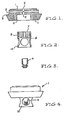
- Figure 1 is a sectional view of a sampling point mounting base
- a convenient circular mounting base (1) is provided.
- Said base is adapted to be mounted to the ceiling in various possible ways to suit circumstances. Accordingly said base is sized to match a standard circular electrical junction box of a type which may be surface-mounted or may have been pre-cast into a concrete floor slab. Said base is also configured for direct surface- mounting.
- Push-fit airtight coupling to the pipe network is facilitated by tapered holes (2) into said base, permitting top entry, side entry, or tee-junction- ing.
- An annular rim (3) is provided for aesthetic appeal and where appropriate, to provide a ledge to hide the end of a run of surface-mounted rectangular conduit.
- the underneath of said base has a deep, tapered cylindrical recess (4), in the centre of which is the actual orifice (5) of said sampling point.
- a cylindrical cartridge assembly (6) consisting of said housing (7) with an integral well to contain said wax adhesive (8) and said heat-collecting plug (9), is adapted to be held by wax adhesion in said recess, to block said sampling point.
- a ventilated protective guard means 10 to prevent damage from thrown objects, which might otherwise cause the seal of said wax to be broken and said heat collecting plug to fall away.
- Said mounting base is provided with counter bored holes (11) positioned at right-angles to the cross- section shown, to facilitate attachment to the ceiling or junction box by means of two screws.
- the heat collecting plug should be of high heat conducting material such as copper, aluminium or ceramic.
- the curve indicates a thermal profile of temperature against time in a test chamber housing various test heads.
- a conventional quartz bulb sprinkler head has a delay time of approximately 13 minutes whereas a conventional thermal detector is in excess of 100 seconds.
- the sampling point assembly of the present invention is a little less than 80 seconds in the arrangement shown.
- a removable cartridge assembly 6 which may be a press fit or threaded.
- the fire brigade may conduct testing of every sampling point at any time, simply be removing said cartridge and introducing test smoke.
- said bases may have said cartridges inserted or removed at will.
- said cartridges are made available with and without said heat-collecting plug installed, such that a cartridge of either type is inserted into every said base.
- FIGS. 6(a), 6(b), 6(c), 6(d), 6(e) and 6(f) show schematically various examples of heat collecting plug or blocking means 9 housed in a recess 8 to shroud and block aperture 5.
- the blocking member 9 is secured into the well by a wax adhesive for example TECHNIWAX 9210 which is an adhesive consisting of a long chain hydrocarbon wax having a melting point in the range of 64 to 68°C.
- a wax adhesive for example TECHNIWAX 9210 which is an adhesive consisting of a long chain hydrocarbon wax having a melting point in the range of 64 to 68°C.
- the material may be thin and have a large surface area such as in Figures 6(a) and 6(f) resulting in relatively short delay times after 67°C is exceeded under test.
- locking members of thin material and relatively small surface area such as Figures 6(b) and 6(d) take longer to break the seal.
- Blocking members having greater mass and relatively high surface area such as Figures 6(c) and 6(e) also exhibited long delay times before breaking away from the wax seal.
- the latent heat of the wax, its mass and the surface area and geometry of the plug all become factors affecting the reaction time of the unit.
- the delay resulting from said reaction time may be of benefit in avoiding false alarms caused by transient but safe rises in temperature.
- the delay time for each example in Figures 6(a) to 6(f) is shown on each Figure.
- FIG. 7 there is shown schematically a reticulation smoke transport system of sampling pipes 23 and 24 leading to various sampling areas to detect the presence of smoke in those areas.
- the transport system leads back to a sampling chamber or tube 22 of the type initially referred to.
- the blocking means may include a temperature responsive bimetallic strip (not shown) blocking the opening to the air sampling pipe.
- the strip may be of various dissimilar metals, such as copper and steel, rivetted or welded together and arranged to distort upon the surrounding temperature level exceeding a predetermined level which is usually indicative of fire.
Landscapes
- Business, Economics & Management (AREA)
- Emergency Management (AREA)
- Physics & Mathematics (AREA)
- General Physics & Mathematics (AREA)
- Fire-Detection Mechanisms (AREA)
Claims (5)
Priority Applications (1)
| Application Number | Priority Date | Filing Date | Title |
|---|---|---|---|
| AT84304549T ATE38444T1 (de) | 1983-07-04 | 1984-07-03 | Rauch-detektor-geraet. |
Applications Claiming Priority (3)
| Application Number | Priority Date | Filing Date | Title |
|---|---|---|---|
| AU116/83 | 1983-07-04 | ||
| AUPG011683 | 1983-07-04 | ||
| AU30236/84A AU573594B2 (en) | 1983-07-04 | 1984-07-03 | Smoke detection apparatus |
Publications (2)
| Publication Number | Publication Date |
|---|---|
| EP0132969A1 EP0132969A1 (fr) | 1985-02-13 |
| EP0132969B1 true EP0132969B1 (fr) | 1988-11-02 |
Family
ID=25621357
Family Applications (1)
| Application Number | Title | Priority Date | Filing Date |
|---|---|---|---|
| EP19840304549 Expired EP0132969B1 (fr) | 1983-07-04 | 1984-07-03 | Appareils détecteurs de fumée |
Country Status (1)
| Country | Link |
|---|---|
| EP (1) | EP0132969B1 (fr) |
Families Citing this family (1)
| Publication number | Priority date | Publication date | Assignee | Title |
|---|---|---|---|---|
| TWI681179B (zh) * | 2013-10-16 | 2020-01-01 | 巴哈馬商愛克斯崔里斯科技有限公司 | 粒子偵測之可定址性技術及其相關方法 |
Family Cites Families (5)
| Publication number | Priority date | Publication date | Assignee | Title |
|---|---|---|---|---|
| CH521649A (de) * | 1970-07-31 | 1972-04-15 | Cerberus Ag | Feuermeldeeinrichtung |
| US4170189A (en) * | 1976-12-27 | 1979-10-09 | Falcon Safety Products, Inc. | Sensor element and assembly for thermally responsive apparatus |
| CH621640A5 (fr) * | 1977-11-21 | 1981-02-13 | Cerberus Ag | |
| CH648943A5 (de) * | 1980-05-09 | 1985-04-15 | Cerberus Ag | Rauchmelder. |
| NL187595C (nl) * | 1981-10-08 | 1991-11-18 | Westinghouse Electrotechniek E | Inrichting voor het detecteren van gas- of rookdeeltjes. |
-
1984
- 1984-07-03 EP EP19840304549 patent/EP0132969B1/fr not_active Expired
Also Published As
| Publication number | Publication date |
|---|---|
| EP0132969A1 (fr) | 1985-02-13 |
Similar Documents
| Publication | Publication Date | Title |
|---|---|---|
| US4608556A (en) | Smoke detection apparatus | |
| CN100390827C (zh) | 火灾及烟雾检测与控制方法 | |
| EP0078442B1 (fr) | Système de détection d'incendie avec détecteur de rapport IR et UV | |
| EP0877995B1 (fr) | Procede d'adaptation dynamique des criteres de detection d'incendie | |
| US5767776A (en) | Fire detector | |
| JP2542306B2 (ja) | 簡単な火災検出器 | |
| US5263543A (en) | External fire prevention system | |
| AU2016204476A1 (en) | Supervision and control method for preventing poor air quality and fire as well as issuing an alarm of a dangerous condition | |
| US5611620A (en) | Method and apparatus for testing heat detectors | |
| US3938115A (en) | Combination smoke and heat detector alarm | |
| KR102523594B1 (ko) | 주방용 화재 감지장치 및 방법 | |
| EP0132969A1 (fr) | Appareils détecteurs de fumée | |
| CN114333222A (zh) | 一种智能消防安全装置的控制方法及系统 | |
| US4833458A (en) | Smoke and fire detector for remote sensing | |
| US3984826A (en) | Condition detector, especially for detecting atmospheric conditions | |
| DK1339476T3 (da) | Fremgangsmåde ved overvågning af filteranlæg | |
| JP3924114B2 (ja) | 滞在限界状態検出方法 | |
| ES465281A1 (es) | Perfeccionamientos en dispositivos de seguridad contra fugasde gas en instalaciones de alimentacion de gas combustible. | |
| CN221327159U (zh) | 一种消防检测用报警装置 | |
| JPS638995A (ja) | クリ−ンル−ムにおける防災用多段階警報設備 | |
| JPH04105665A (ja) | ボンベストッカー等の防災設備 | |
| SU454029A1 (ru) | Тепловой пожарный извещатель | |
| JPH0317801Y2 (fr) | ||
| Bukowski | Techniques for fire detection | |
| JPH02173896A (ja) | 火災警報装置 |
Legal Events
| Date | Code | Title | Description |
|---|---|---|---|
| PUAI | Public reference made under article 153(3) epc to a published international application that has entered the european phase |
Free format text: ORIGINAL CODE: 0009012 |
|
| AK | Designated contracting states |
Designated state(s): AT BE CH DE FR GB IT LI LU NL SE |
|
| 17P | Request for examination filed |
Effective date: 19850810 |
|
| 17Q | First examination report despatched |
Effective date: 19861030 |
|
| D17Q | First examination report despatched (deleted) | ||
| GRAA | (expected) grant |
Free format text: ORIGINAL CODE: 0009210 |
|
| RAP1 | Party data changed (applicant data changed or rights of an application transferred) |
Owner name: COLE, MARTIN TERENCE |
|
| AK | Designated contracting states |
Kind code of ref document: B1 Designated state(s): AT BE CH DE FR GB IT LI LU NL SE |
|
| PG25 | Lapsed in a contracting state [announced via postgrant information from national office to epo] |
Ref country code: SE Effective date: 19881102 Ref country code: NL Effective date: 19881102 Ref country code: IT Free format text: LAPSE BECAUSE OF FAILURE TO SUBMIT A TRANSLATION OF THE DESCRIPTION OR TO PAY THE FEE WITHIN THE PRESCRIBED TIME-LIMIT;WARNING: LAPSES OF ITALIAN PATENTS WITH EFFECTIVE DATE BEFORE 2007 MAY HAVE OCCURRED AT ANY TIME BEFORE 2007. THE CORRECT EFFECTIVE DATE MAY BE DIFFERENT FROM THE ONE RECORDED. Effective date: 19881102 Ref country code: BE Effective date: 19881102 Ref country code: AT Effective date: 19881102 |
|
| REF | Corresponds to: |
Ref document number: 38444 Country of ref document: AT Date of ref document: 19881115 Kind code of ref document: T |
|
| REF | Corresponds to: |
Ref document number: 3475018 Country of ref document: DE Date of ref document: 19881208 |
|
| ET | Fr: translation filed | ||
| NLV1 | Nl: lapsed or annulled due to failure to fulfill the requirements of art. 29p and 29m of the patents act | ||
| PG25 | Lapsed in a contracting state [announced via postgrant information from national office to epo] |
Ref country code: LU Free format text: LAPSE BECAUSE OF NON-PAYMENT OF DUE FEES Effective date: 19890731 |
|
| PLBE | No opposition filed within time limit |
Free format text: ORIGINAL CODE: 0009261 |
|
| STAA | Information on the status of an ep patent application or granted ep patent |
Free format text: STATUS: NO OPPOSITION FILED WITHIN TIME LIMIT |
|
| 26N | No opposition filed | ||
| REG | Reference to a national code |
Ref country code: GB Ref legal event code: 732E |
|
| PGFP | Annual fee paid to national office [announced via postgrant information from national office to epo] |
Ref country code: CH Payment date: 19940608 Year of fee payment: 11 |
|
| PG25 | Lapsed in a contracting state [announced via postgrant information from national office to epo] |
Ref country code: LI Effective date: 19950731 Ref country code: CH Effective date: 19950731 |
|
| PGFP | Annual fee paid to national office [announced via postgrant information from national office to epo] |
Ref country code: DE Payment date: 19951128 Year of fee payment: 12 |
|
| PGFP | Annual fee paid to national office [announced via postgrant information from national office to epo] |
Ref country code: FR Payment date: 19960105 Year of fee payment: 13 |
|
| REG | Reference to a national code |
Ref country code: CH Ref legal event code: PL |
|
| PGFP | Annual fee paid to national office [announced via postgrant information from national office to epo] |
Ref country code: GB Payment date: 19960702 Year of fee payment: 13 |
|
| PG25 | Lapsed in a contracting state [announced via postgrant information from national office to epo] |
Ref country code: DE Effective date: 19970402 |
|
| REG | Reference to a national code |
Ref country code: GB Ref legal event code: 732E |
|
| PG25 | Lapsed in a contracting state [announced via postgrant information from national office to epo] |
Ref country code: GB Free format text: LAPSE BECAUSE OF NON-PAYMENT OF DUE FEES Effective date: 19970703 |
|
| GBPC | Gb: european patent ceased through non-payment of renewal fee |
Effective date: 19970703 |
|
| PG25 | Lapsed in a contracting state [announced via postgrant information from national office to epo] |
Ref country code: FR Free format text: LAPSE BECAUSE OF NON-PAYMENT OF DUE FEES Effective date: 19980331 |
|
| REG | Reference to a national code |
Ref country code: FR Ref legal event code: ST |