EP0133077A1 - Trainingsgerät, insbesondere für Kletterer - Google Patents
Trainingsgerät, insbesondere für Kletterer Download PDFInfo
- Publication number
- EP0133077A1 EP0133077A1 EP84401393A EP84401393A EP0133077A1 EP 0133077 A1 EP0133077 A1 EP 0133077A1 EP 84401393 A EP84401393 A EP 84401393A EP 84401393 A EP84401393 A EP 84401393A EP 0133077 A1 EP0133077 A1 EP 0133077A1
- Authority
- EP
- European Patent Office
- Prior art keywords
- bar
- suspension
- accessories
- zone
- straps
- Prior art date
- Legal status (The legal status is an assumption and is not a legal conclusion. Google has not performed a legal analysis and makes no representation as to the accuracy of the status listed.)
- Withdrawn
Links
- 241001503987 Clematis vitalba Species 0.000 title 1
- 239000000725 suspension Substances 0.000 claims description 42
- 239000006261 foam material Substances 0.000 claims description 3
- 230000003387 muscular Effects 0.000 claims 1
- 238000000034 method Methods 0.000 description 4
- 241001573881 Corolla Species 0.000 description 2
- 230000003100 immobilizing effect Effects 0.000 description 2
- 238000009434 installation Methods 0.000 description 2
- 238000002955 isolation Methods 0.000 description 2
- 239000000463 material Substances 0.000 description 2
- 230000000149 penetrating effect Effects 0.000 description 2
- 230000009194 climbing Effects 0.000 description 1
- 230000000295 complement effect Effects 0.000 description 1
- 230000006835 compression Effects 0.000 description 1
- 238000007906 compression Methods 0.000 description 1
- 238000009432 framing Methods 0.000 description 1
- 210000002976 pectoralis muscle Anatomy 0.000 description 1
- 230000000717 retained effect Effects 0.000 description 1
- 239000011435 rock Substances 0.000 description 1
- 238000000926 separation method Methods 0.000 description 1
- 239000007787 solid Substances 0.000 description 1
Images


Classifications
-
- A—HUMAN NECESSITIES
- A63—SPORTS; GAMES; AMUSEMENTS
- A63B—APPARATUS FOR PHYSICAL TRAINING, GYMNASTICS, SWIMMING, CLIMBING, OR FENCING; BALL GAMES; TRAINING EQUIPMENT
- A63B23/00—Exercising apparatus specially adapted for particular parts of the body
- A63B23/035—Exercising apparatus specially adapted for particular parts of the body for limbs, i.e. upper or lower limbs, e.g. simultaneously
- A63B23/12—Exercising apparatus specially adapted for particular parts of the body for limbs, i.e. upper or lower limbs, e.g. simultaneously for upper limbs or related muscles, e.g. chest, upper back or shoulder muscles
- A63B23/16—Exercising apparatus specially adapted for particular parts of the body for limbs, i.e. upper or lower limbs, e.g. simultaneously for upper limbs or related muscles, e.g. chest, upper back or shoulder muscles for hands or fingers
-
- A—HUMAN NECESSITIES
- A63—SPORTS; GAMES; AMUSEMENTS
- A63B—APPARATUS FOR PHYSICAL TRAINING, GYMNASTICS, SWIMMING, CLIMBING, OR FENCING; BALL GAMES; TRAINING EQUIPMENT
- A63B21/00—Exercising apparatus for developing or strengthening the muscles or joints of the body by working against a counterforce, with or without measuring devices
- A63B21/16—Supports for anchoring force-resisters
- A63B21/1618—Supports for anchoring force-resisters on a door or a door frame
- A63B21/1663—Supports for anchoring force-resisters on a door or a door frame for anchoring between a door and the door frame
-
- A—HUMAN NECESSITIES
- A63—SPORTS; GAMES; AMUSEMENTS
- A63B—APPARATUS FOR PHYSICAL TRAINING, GYMNASTICS, SWIMMING, CLIMBING, OR FENCING; BALL GAMES; TRAINING EQUIPMENT
- A63B2208/00—Characteristics or parameters related to the user or player
- A63B2208/12—Characteristics or parameters related to the user or player specially adapted for children
Definitions
- the subject of the present invention is an apparatus for bodybuilding exercises, more especially intended for mountaineers, comprising a cylindrical bar and means making it possible to immobilize said bar at a determined height above the ground.
- the present invention aims to remedy this situation and, for this purpose, it provides an apparatus of the aforementioned type in which the bar has, along one of its generators, at least one flat or curved digital suspension zone. , or supports one or more accessories with such an area.
- this area consists of the surface of a strip fixed on the periphery of the bar.
- the suspension zone is formed by the suitably deformed surface of the bar itself.
- the bar can be flat or curved.
- the bar is cylindrical and the suspension zone is formed either in a rigid or semi-rigid sheath surrounding the bar, or in one or more accessories capable of equipping said bar.
- the device according to the invention thus allows the user to hang by the fingertips by taking hold of the digital suspension zone (s).
- This zone can occupy the center of the bar or two ranges symmetrical with respect to the middle of the bar.
- the device according to the invention can be used for other purposes and that it is thus versatile.
- the device according to the invention comprises a removable envelope capable of surrounding the bar, with the interposition of a removable sleeve made of foam material, to form a cylindrical bar with rigid core and flexible periphery.
- the means making it possible to immobilize the bar at a determined height above the ground can be constituted by jacks, which makes it possible to adapt the bar exactly to the frame of a door, or by separate means permanently fixed , such as a couple of pitons.
- the means making it possible to immobilize the bar at a determined height above the ground are constituted by an elongated element forming a stop capable of being joined parallel to the bar by a pair of straps.
- This structure it is possible to suspend the bar by placing the straps astride the top of a door, the element forming a stop immobilizing the bar once the door is closed.
- This suspension method which is similar to the method of immobilizing the toe clip described in the aforementioned patent application No. 83 06599, has the advantage, on the one hand, of being able to leave the device in place on top of the door without affecting its closing and, on the other hand, to use the vertical surface of the closed door as support for the back of the user. It is clear that the flat bars with jacks have none of these advantages since their installation prohibits the closing of the door and - that the user necessarily works with the door open, without back support.
- the latter comprises a pair of deep grooves adapted to receive the straps and each emerging, on the surface of the element forming a stop, in a surface groove of lesser depth but of greater width, adapted to receive a semi-circular clamp of a width substantially equal to that of the surface groove and coming to be embedded in the latter.
- the clamp maintains, without touching it, the strap in the deep throat which avoids an unfortunate separation, while allowing the strap to slide around the element forming a stop.
- the straps are adjustable in length which allows the bar to be suspended at the desired height and / or to modify this height according to the user. This is particularly advantageous if the device according to the invention is used by a small person or by a child because it is possible, when the device is left straddling the top of a door, to " lower the bar at the time of use and then raise it. Thus, leaving the device in place does not hinder passage even if the device is used by a small person.
- the bar is preferably telescopic and it comprises, on the one hand, elastic means tending to expand it and, on the other hand, removable handles mounted at the two ends of the bar. In this way it is possible, after removal of the means for suspending it, using the bar as a bicep weight training device by working in compression.
- the device also comprises at least one cable joining the handles together on either side of the bar. It is thus possible to use the device in extension (by pulling on the cables) for bodybuilding of the dorsal and pectoral muscles.
- the bar may also have lights suitable for the temporary installation of suspension accessories.
- the useful part of the suspension accessories may be integral with a tube, or portions of aligned tubes, or rings or hooks, adapted to be threaded onto the bar.
- Figure 1 shows a cylindrical bar 1 provided with a strip 2.
- the exposed face 3 of this strip is flat while its opposite face 3 'is of a curvature which matches that of the bar 1.
- Screws 4 immobilize the strip 2 on the bar 1.
- the strip 2 offers a flat surface 3 adapted to a digital suspension.
- the digital suspension zone can be provided by a flat 5 ( Figure 2) or a hollow deformation 6 ( Figure 3) of the bar 1 itself.
- Another possibility consists in surrounding the bar 1 with a sheath 7 of rigid or semi-rigid material having a flat or, as is the case in FIG. 4, a recess 8.
- the digital suspension zone does not necessarily affect the center of the bar: there can be, for example, two zones or groups of suspension zones symmetrical with respect to the middle of the bar.
- the bar of Figure 5 has two groups of imprints 9 adapted to receive the end of the user's fingers.
- FIG. 6 represents another version of the bar according to the invention.
- sliding tubes 10 are engaged in the bar 1. More specifically, the end of the tubes 10 engaged in the bar 1 has a corolla 11 adapted to come into abutment against a plug 12 traversed by the tubes 10 and closing the bar 1.
- a spring 13 tends to spread the sliding tubes 10 which cannot however be detached from the bar 1, their corolla 11 abutting against the plugs 12.
- the tubes 10 are closed by a plug 14 and are provided with a removable handle 15.
- This handle 15 has a blind hole 16 adapted to temporarily receive the end of the bar 1.
- the handles 15 have a groove 17 and a bore 18.
- a cable 19, of which only the upper strand has been shown in FIG. 6, goes from one handle to another, from on either side of the bar 1.
- the cable 19 forms a loop closed by a knot which is received in the bore 18.
- a handle 15 ′ which has a blind hole 11 ′ adapted to be threaded onto the end of the bar 1 and a pair of slots 20 adapted to receive respectively an upper cable 19 ′ and a lower cable (not shown), these slots 20 being equipped with self-clamping means 21.
- the device of FIG. 6 can also be used as a compressor (the user trying to bring the handles 15 or 15 'apart) or as an expander (the user trying to separate the strands of the cable 19 from each other).
- the sliding tubes 10 can have elongated 22 and circular 23 holes adapted to the fitting of a suspension accessory 24.
- This accessory which of course has its symmetry not shown, can be used for hanging bungee cords or other articles as well as for a digital suspension, if the loops 25 of the accessory are large enough to allow the passage of the phalanges of the user.
- Figure 9 shows an embodiment of the bar according to the invention provided with jacks whose bearing faces 27 are capable of abutting against the frame of a door.
- a lever 28 capable of penetrating a bore 29 makes it possible to perfect the expansion of the jacks and to properly block the bearing faces 27 on the door frame.
- the digital suspension zone is constituted, on the one hand, by the loops 25 of the accessories 24 and, on the other hand. as in FIG. 2, by a flat 5 provided on the bar 1.
- the flat 5 could be extended all along the bar 1.
- the flat could occupy two symmetrical ranges with respect to the middle of the bar 1, such as the imprints 9 in FIG. 5.
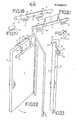
- Figures 10, 11 and 12 show the device according to the invention provided with means for wedging it above or below a door and to use it, respectively as a suspension bar or as toe clips.
- the strip has an upper face 3 "curved.
- the central area of the bar is partially surrounded by an open sleeve 31 of foam material whose thickness is very slightly .superior to that of the strip 2.
- a rectangular envelope 32 made of a flexible material closes on itself by surrounding the sleeve 31. To do this, the opposite ends of the envelope 32 are provided with complementary elements ( loops 33 and hooks 34) of a self-gripping tape, of the type which is marketed under the brand Velcro.
- the assembly formed by the bar 1, the sleeve 31 and the casing 32 thus constitutes a bar with rigid core and flexible periphery
- the bar 1 is connected parallel to a solid cylinder 35, forming a stop, by a pair of straps 36.
- the straps 36 form a loop 37 closed at d emeure and whose diameter is such that the bar 1 can be slid there without difficulty.
- Each strap 36 then passes around a groove 38 provided in the cylinder 35 and is brought back around the bar 1.
- the groove 38 opens at the surface of the cylinder 35 in a wider groove 39.
- a clamp 40 which fits into the groove 39 makes it possible to hold the strap 36 in the groove 38 without preventing this strap from sliding around the cylinder 35.
- the free end 41 of the strap 36 which surrounds the bar 1 is folded over the upper strand 42 of the strap and immobilized against this strand, on the one hand, by a self-gripping tape 43 and, on the other hand, by a loop 44. It is important that the upper and lower strands 42 and 42 'of the straps 36 are as close together as possible for the reasons that we will see later, this approximation being provided on the one hand by passers-by 44 and, on the other hand, by the narrowness of the opening 45 of the clamp 40.
- FIGS. 22 and 23 show the apparatus in the stripped of its envelope 32 and of its sleeve 31.
- the straps 36 are placed astride the top of a door P.
- the thickness of the straps 36 is such that they do not hinder the closing of the door.
- Figure 23 also shows the door in the closed state provided with the device according to the invention.
- the bar 1 is coated with its sleeve 31 and its casing 32.
- the same device could be used as a footrest. Indeed, instead of being placed astride the top of door P, the device could be slid under the door. Once the door is closed, the bar 1 is immobilized by the stop formed by the cylinder 35 at a distance from the door which is determined by the length of the straps 36. In the case of use as toe clips, the bar 1 must obviously be coated with the sleeve 31 and the casing 32 so that the contact between the kick of the user and the device is painless. A toe clip of similar design is described in the aforementioned patent application 83 06599.
- Hooks 46 secured to the door P can allow the device to be left permanently in position on the top of the door without risk of the device falling when the door is opened.
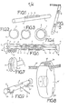
- FIG. 13 shows different accessories that can equip the device according to the invention.
- a suspension block formed by a cylinder 47 and a plate having holes 48 is threaded on the end of the bar 1.
- the diameter of the holes is chosen so that it allows the user to insert and hang their fingers on it.
- the accessory shown in FIG. 14 essentially differs from the previous one in that the cylinder 47 is in two parts 47a, 47b spaced from one another, which makes it possible to mount it on either side of the strap 36
- This arrangement has the advantage of avoiding that, during the use of the device, the accessory inadvertently slides towards the extreme edge of the bar 1.
- FIG. 15 shows an embodiment of the device according to the invention in which the cylinder 35 and the bar 1 are not joined by an adjustable strap but by a strap of fixed length 36 'and a bungee cord 49.
- the strap 36 'and the bungee cords 49 are connected by means of a ring 50.
- the end 51 of the bungee cords surrounds the ring 50 and is closed in a loop by an appropriate link.
- the opposite end 51 ′ of the bungee cord surrounds the bar 1 and forms a loop closed by a link.
- a tubular roller 52 (shown in isolation in Figure 16) is interposed between the bar 1 and the loop formed by the end 51 'of the bungee cord to facilitate the sliding of this loop on the bar 1 and therefore the establishment or removal of the cylinder 35 / strap 36 '/ bungee 49 assembly.
- FIG. 18 On the end of the bar 1 is slid a suspension accessory 53 shown in isolation in Figure 17. Again this accessory 53 can be used for a digital suspension or the attachment of another accessory.
- Figures 18 to 21 show other types of accessories that can be used with the bar according to the invention. tion.
- the bar has a series of annular slots 23 and elongated slots 22 making it possible to install suspension accessories 24 ending in lugs 52 adapted to penetrate and to be temporarily retained in a pair of slots 22, 23.
- the distribution of the circular lights 23 and the elongated lights 22 on the bar 1 makes it possible to mount the suspension accessories 24 both at the ends of the bar and in the central zone of the latter.
- the legs 52 of the suspension accessories 24 do not necessarily project outward. They can be re-entrant like the legs 52 ′ in FIG. 19.
- the accessories 24 ′ can be provided at their opposite ends with open rings 54 in which the ends of the bar 1 can be slid.
- the suspension accessory can consist, not of a single row of loops as shown in FIGS. 18 to 20, but of a double row of loops 55 joined between them by a semi-circular bridge 56 which can. be threaded on the ends of the bar 1.
- the invention is not limited neither to the embodiments described and shown, nor to the applications given by way of examples.
- the device according to the invention could also be provided with accessories such as those mentioned above, for fixing, for example, bungee cords for carrying out other exercises. strength training for arms or legs.
Landscapes
- Health & Medical Sciences (AREA)
- Orthopedic Medicine & Surgery (AREA)
- General Health & Medical Sciences (AREA)
- Physical Education & Sports Medicine (AREA)
- Life Sciences & Earth Sciences (AREA)
- Biophysics (AREA)
- Medicines Containing Material From Animals Or Micro-Organisms (AREA)
- Walking Sticks, Umbrellas, And Fans (AREA)
- Mutual Connection Of Rods And Tubes (AREA)
Applications Claiming Priority (2)
| Application Number | Priority Date | Filing Date | Title |
|---|---|---|---|
| FR8311679 | 1983-07-13 | ||
| FR8311679A FR2548912B1 (fr) | 1983-07-13 | 1983-07-13 | Appareil de musculation destine notamment aux alpinistes |
Publications (1)
| Publication Number | Publication Date |
|---|---|
| EP0133077A1 true EP0133077A1 (de) | 1985-02-13 |
Family
ID=9290794
Family Applications (1)
| Application Number | Title | Priority Date | Filing Date |
|---|---|---|---|
| EP84401393A Withdrawn EP0133077A1 (de) | 1983-07-13 | 1984-06-29 | Trainingsgerät, insbesondere für Kletterer |
Country Status (3)
| Country | Link |
|---|---|
| EP (1) | EP0133077A1 (de) |
| JP (1) | JPS6075068A (de) |
| FR (1) | FR2548912B1 (de) |
Cited By (2)
| Publication number | Priority date | Publication date | Assignee | Title |
|---|---|---|---|---|
| FR2605521A1 (fr) * | 1986-10-27 | 1988-04-29 | Moreno Gilbert | Perfectionnement aux engins de gymnastique dits espaliers |
| CN1326340C (zh) * | 2003-10-21 | 2007-07-11 | 华为技术有限公司 | 无源光网络的动态带宽分配装置及方法 |
Citations (3)
| Publication number | Priority date | Publication date | Assignee | Title |
|---|---|---|---|---|
| GB819360A (en) * | 1956-03-07 | 1959-09-02 | David William Cadwaladr | Bar device for remedial exercises |
| FR1290499A (fr) * | 1961-05-03 | 1962-04-13 | Appareil de gymnastique | |
| CH393160A (de) * | 1961-04-07 | 1965-05-31 | Abplanalp Arthur | Turngerät zum Stärken der Körpermuskulatur |
Family Cites Families (2)
| Publication number | Priority date | Publication date | Assignee | Title |
|---|---|---|---|---|
| US4048062A (en) * | 1976-04-22 | 1977-09-13 | Uop Inc. | Aromatic extraction with solvent recovery and regeneration |
| PH17150A (en) * | 1980-02-14 | 1984-06-13 | Texaco Development Corp | Recovery of solvent in hydrocarbon extraction system |
-
1983
- 1983-07-13 FR FR8311679A patent/FR2548912B1/fr not_active Expired
-
1984
- 1984-06-29 EP EP84401393A patent/EP0133077A1/de not_active Withdrawn
- 1984-07-13 JP JP14587984A patent/JPS6075068A/ja active Pending
Patent Citations (3)
| Publication number | Priority date | Publication date | Assignee | Title |
|---|---|---|---|---|
| GB819360A (en) * | 1956-03-07 | 1959-09-02 | David William Cadwaladr | Bar device for remedial exercises |
| CH393160A (de) * | 1961-04-07 | 1965-05-31 | Abplanalp Arthur | Turngerät zum Stärken der Körpermuskulatur |
| FR1290499A (fr) * | 1961-05-03 | 1962-04-13 | Appareil de gymnastique |
Cited By (2)
| Publication number | Priority date | Publication date | Assignee | Title |
|---|---|---|---|---|
| FR2605521A1 (fr) * | 1986-10-27 | 1988-04-29 | Moreno Gilbert | Perfectionnement aux engins de gymnastique dits espaliers |
| CN1326340C (zh) * | 2003-10-21 | 2007-07-11 | 华为技术有限公司 | 无源光网络的动态带宽分配装置及方法 |
Also Published As
| Publication number | Publication date |
|---|---|
| FR2548912B1 (fr) | 1985-12-13 |
| FR2548912A1 (fr) | 1985-01-18 |
| JPS6075068A (ja) | 1985-04-27 |
Similar Documents
| Publication | Publication Date | Title |
|---|---|---|
| CA2340076C (fr) | Baton de ski | |
| CH665777A5 (fr) | Appareil de mecanotherapie. | |
| CA2003596A1 (fr) | Dispositif de liaison d'une poignee notamment de d'un baton de ski a la main d'un utilisateur | |
| FR2777467A3 (fr) | Structure de poignee pour extenseur de poitrine | |
| FR2570945A1 (fr) | Sangle de levage | |
| EP0133077A1 (de) | Trainingsgerät, insbesondere für Kletterer | |
| EP0256072A1 (de) | Vorrichtung zum muskeltraining, insbesondere einsetzbar für heilgymnastische behandlungen. | |
| FR2785783A1 (fr) | Dispositif enfile-bas a poignees articulees | |
| FR2657022A1 (fr) | Appareil pour gravir un poteau. | |
| WO1997017569A1 (fr) | Ensemble de support d'une perche de prise de son | |
| FR2544617A1 (fr) | Cale-pieds adapte pour l'entrainement musculaire des abdominaux | |
| EP1557198A1 (de) | Schutzgürtel | |
| FR2797435A1 (fr) | Dispositif destine a tenir et a transporter en suspension avec reduction d'effort les bagages et paquets d'une seule main | |
| CH162766A (fr) | Appareil de culture physique. | |
| FR2776172A1 (fr) | Dispositif de suspension d'un verre pour degustation et cocktail | |
| FR2903320A3 (fr) | Tapis roulant d'excercice | |
| WO2003000349A2 (fr) | Appareil portatif de culture physique a reglage rapide | |
| FR2764963A1 (fr) | Dispositif pour maintenir une canne debout | |
| FR2761608A3 (fr) | Dispositif de sauvetage permettant de faire descendre une personne d'un immeuble en feu | |
| FR2755599A1 (fr) | Dispositif pour enfiler un vetement sur au moins un membre inferieur d'un etre humain | |
| FR2598066A1 (fr) | Dispositif porte-parapluie | |
| EP3181205B1 (de) | Tragemethode für skier | |
| FR2764962A1 (fr) | Dispositif pour maintenir une canne debout | |
| FR2889814A1 (fr) | Dispositif pour la descente en rappel | |
| FR2842118A1 (fr) | Sac de frappe comprenant des moyens de rembourrage susceptibles de faire office de tapis d'exercice au sol |
Legal Events
| Date | Code | Title | Description |
|---|---|---|---|
| PUAI | Public reference made under article 153(3) epc to a published international application that has entered the european phase |
Free format text: ORIGINAL CODE: 0009012 |
|
| AK | Designated contracting states |
Designated state(s): BE CH DE GB IT LI |
|
| STAA | Information on the status of an ep patent application or granted ep patent |
Free format text: STATUS: THE APPLICATION IS DEEMED TO BE WITHDRAWN |
|
| 18D | Application deemed to be withdrawn |
Effective date: 19851014 |