EP0133128A1 - Dispositif de protection à surintensité de courant - Google Patents
Dispositif de protection à surintensité de courant Download PDFInfo
- Publication number
- EP0133128A1 EP0133128A1 EP84401561A EP84401561A EP0133128A1 EP 0133128 A1 EP0133128 A1 EP 0133128A1 EP 84401561 A EP84401561 A EP 84401561A EP 84401561 A EP84401561 A EP 84401561A EP 0133128 A1 EP0133128 A1 EP 0133128A1
- Authority
- EP
- European Patent Office
- Prior art keywords
- circuit
- timer
- current
- memory
- output
- Prior art date
- Legal status (The legal status is an assumption and is not a legal conclusion. Google has not performed a legal analysis and makes no representation as to the accuracy of the status listed.)
- Granted
Links
- 229920006395 saturated elastomer Polymers 0.000 claims description 3
- 230000003068 static effect Effects 0.000 claims description 2
- 238000009434 installation Methods 0.000 abstract description 3
- 230000001052 transient effect Effects 0.000 description 9
- 239000003990 capacitor Substances 0.000 description 6
- 238000010586 diagram Methods 0.000 description 6
- 230000006870 function Effects 0.000 description 5
- 239000004020 conductor Substances 0.000 description 4
- 238000001514 detection method Methods 0.000 description 4
- 230000004044 response Effects 0.000 description 3
- 230000004913 activation Effects 0.000 description 2
- 238000013459 approach Methods 0.000 description 2
- 230000000903 blocking effect Effects 0.000 description 1
- 230000000295 complement effect Effects 0.000 description 1
- 230000007423 decrease Effects 0.000 description 1
- 230000003111 delayed effect Effects 0.000 description 1
- 230000000694 effects Effects 0.000 description 1
- 230000008030 elimination Effects 0.000 description 1
- 238000003379 elimination reaction Methods 0.000 description 1
- 230000002349 favourable effect Effects 0.000 description 1
- 230000010355 oscillation Effects 0.000 description 1
- 230000002028 premature Effects 0.000 description 1
- 230000001681 protective effect Effects 0.000 description 1
Images


Classifications
-
- H—ELECTRICITY
- H02—GENERATION; CONVERSION OR DISTRIBUTION OF ELECTRIC POWER
- H02H—EMERGENCY PROTECTIVE CIRCUIT ARRANGEMENTS
- H02H1/00—Details of emergency protective circuit arrangements
- H02H1/04—Arrangements for preventing response to transient abnormal conditions, e.g. to lightning or to short duration over voltage or oscillations; Damping the influence of DC component by short circuits in AC networks
-
- H—ELECTRICITY
- H02—GENERATION; CONVERSION OR DISTRIBUTION OF ELECTRIC POWER
- H02H—EMERGENCY PROTECTIVE CIRCUIT ARRANGEMENTS
- H02H3/00—Emergency protective circuit arrangements for automatic disconnection directly responsive to an undesired change from normal electric working condition with or without subsequent reconnection ; integrated protection
- H02H3/08—Emergency protective circuit arrangements for automatic disconnection directly responsive to an undesired change from normal electric working condition with or without subsequent reconnection ; integrated protection responsive to excess current
Definitions
- the subject of the invention is a selective overcurrent amperometric protection device, intended to operate on alternating current, of the type comprising means for rectifying the two half-waves and means for comparing the instantaneous value of the rectified current and a value of threshold (s). It finds a particularly important application in the protection of very high voltage installations (in particular at the 400 kV voltage of the French national network) against short circuits.
- a protection device of the type defined above is known (DE-A-1815 200).
- the overcurrent protection relay of this device is controlled in response to the result of a comparison between the peak value of a positive half-wave, then of the negative half-wave which follows it.
- the two peak values are stored for this purpose.
- This solution does not allow a satisfactory distinction to be made between transient currents and short-circuit currents.
- DE-A-24 46 447 describes a similar approach. If a threshold is exceeded, there is activation of a first monostable then, if the new threshold is exceeded during the next alternation, there is activation of an actuating member.
- the invention aims to provide a selective protection device, rapidly discriminating between the two types of current likely to appear and, consequently, making it possible to adopt a low level of protection without the risk of numerous trips. untimely.
- the invention uses the fact that the magnetizing currents in transient conditions exhibit a variation as a function of time very different from the shape of the short-circuit currents in permanent and transient conditions.
- the curve representative of the intensity of a magnetizing current in transient regime as a function of time t, consists of alternations of high amplitude separated by alternations of opposite sign, practically zero.
- the envelope of the vertices of the half-waves decreases and tends towards zero when one approaches the steady state.
- the short-circuit current in steady state corresponds to a sinusoidal function, so that the same amplitude is found, in absolute value, at intervals T / 2 (T being the period, from 20 ms in the case of an alternating current at 50 Hz).
- the problem is however much less simple than it appears at first sight, because there can be establishment of the short-circuit current with a transient mode.
- the maximum asymmetry corresponds to a variation of the current as a function of time of the form:
- the second term is only important when switching on the current.
- the function becomes comparable to that representing the fault current in steady state as soon as t exceeds approximately 5 T ( Figure 3).
- a protection device making it possible to ensure good discrimination despite the possibility of such a situation, comprises in order to carry out, in the event of an overshoot, a new comparison after a time equal to 1 / 2T + ⁇ T (T being the nominal period of the alternating current and ⁇ T a fraction of T on the order of a tenth) after the overshoot and for actuating means for triggering the device in the event of renewal of the overshoot during the new comparison.
- the device detects, at time t 0 , the exceeding of the threshold or setpoint value s by the intensity of the current.
- This instant t 0 marks the start of a time delay 1/2 (T + ⁇ T), T being the nominal period and AT a time interval which will usually be chosen at a value equal to approximately 10% of the period.
- the duration of the time delay will be 11 ms for a network at 50 Hz where, in steady state, the same amplitude is found in absolute value every 10 ms.
- a short-circuit current of the kind shown in Figure 2 where the alternations are symmetrical, we are in ideal conditions for switching on and the device will operate 11 ms after having detected a first crossing of the threshold.
- the device If the relationship between the fault current and the va their threshold current efficiency is high enough (> 2), the device also works quickly. On the other hand, if this ratio is less than 2, its operation may be delayed by a few periods and will also depend on the time constant of the installation (a low L / R results in faster operation. In practice, it can be seen that the extension of the response time only becomes noticeable when the effective value of the fault current is very little greater than the threshold value, which represents a minor drawback, the level of protection being low. As soon as the ratio between the value rms of the fault current and the rms value of the threshold current exceeds 1.5, the response time drops to a value of the order of 15 ms for a current at 50 Hz.
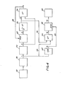
- the device shown in Figure 4 in the form of a block diagram and an embodiment of which, consisting of static elements supplied with voltages of +15 V and -15 V, is given in Figure 5, comprises an input element constituted by a circuit of detection and rectification 12 which receives an input current from a current transformer mounted on the line to be monitored.
- This detector 12 includes an operational amplifier 13 mounted as a differential and designed to provide an output signal during the time intervals when the current in the line to be monitored exceeds an adjustable threshold value using a potentiometer 14 ( Figure 6A ).
- the voltage threshold chosen will generally be very low, typically between 0 and 1 V. Consequently, the associated rectifying circuit must be sufficiently developed so that the forward voltage of the rectifying diodes does not introduce any error.
- the rectifier and detector circuit 12 drives a detection circuit supplemented in logic form 18 alternately supplying an output voltage zero or equal to the supply voltage (+15 V in the case illustrated), but complementary.
- An inverter circuit 20 located at the output comprising like the previous one transistor alternately blocked and saturated, makes it possible to supply at its output a logic signal of polarity adapted to the attack on a memory circuit 22.
- This circuit is also produced using transistors working alternately at blocking and saturation, by example of NPN transistors of type 2N 2221A mounted in rocker.
- This locking memory 22 in turn attacks a timer 24 of duration 1 / 2T + AT.
- This timer 24 can have the constitution shown in FIG.
- a transistor 18 which, depending on whether it is conductive or blocked, short-circuits the capacitor 20 or allows its charging at constant current via a second transistor 22
- a resistor 24 in the load circuit of 120 kOhm
- a potentiometer 26 will generally be placed in the discharge circuit of the capacitor 20, to avoid the charge transfer oscillation.
- the timer 24 and the detector 20 attack an AND circuit 34 constituted by two circuits similar to those adopted for circuits 18 and 20.
- the transistor 36 output of this AND circuit is alternately blocked and saturated.
- the output of the AND circuit 36 is brought back by a conductor 38 to the reset input of the memory 22.
- the part of the device made up of circuits 20, 22, 24 and 34 can be regarded as intended to ensure discrimination.
- the electromagnetic output relay 40 intended to effect tripping is controlled by a second branch which includes an input delay circuit 42 identical to circuit 24 but with a T / 2 delay, and a test circuit 44 formed by a AND circuit having the same constitution as circuit 34.
- This AND circuit 44 receives the direct signal from circuit 18, before delay, by a conductor 46, and the output signal of the timer 24, by a conductor 50.
- the role of the timed circuit 42 is to control the resetting of a memory 52, identical to memory 22, by a conductor 54
- the output of the memory drives the relay 40 via a switching transistor 56.
- the outputs of the detectors 18 and 20 are inverted (lines 1 and 2).
- the change in logic level at point 2 is written to memory 22 at time t 0 (line 3).
- the charging time of the capacitor 20 of this circuit 42 is limited to the time interval during which the current is below the threshold (line 7). Consequently, the circuit 42 cannot at any time supply a reset signal to the memory 52 and it will be the same during the following half-cycles.
- the AND circuit 44 receives signals on its two inputs, coming from points 1 and 5 (line 9) and excites relay 40. The trip occurs and is maintained until elimination of the fault + T / 2.
Landscapes
- Engineering & Computer Science (AREA)
- Power Engineering (AREA)
- Emergency Protection Circuit Devices (AREA)
- Protection Of Transformers (AREA)
Abstract
Description
- L'invention a pour objet un dispositif de protection ampéremé- trique sélectif à surintensité de courant, destiné à fonctionner en courant alternatif, du type comprenant des moyens de redressement des deux alternances et des moyens pour comparer la valeur instantanée du courant redressé et une valeur de seuil (s). Elle trouve une application particulièrement importante dans la protection des installations à très haute tension (notamment à la tension de 400 kV du réseau national français) contre les court-circuits.
- L'un des inconvénients des dispositifs de protection existants est qu'ils risquent d'être sollicités aussi bien par l'appel de courant magnétisant intense en régime transitoire lors de la mise en tension de grosses machines, notamment de transformateurs de grande puissance, que par un courant de court-circuit.En conséquence, ces dispositifs existants entraînent des déclenchements intempestifs à la mise sous tension des transformateurs si l'on recherche un niveau de protection relativement bas, c'est-à-dire correspondant à un courant de court-circuit faible. Ces déclenchements intempestifs imposent aux transformateurs des contraintes supplémentaires du fait d'un nombre de mises sous tension supérieur à la normale et provoquent une usure prématurée des disjoncteurs de protection, du fait des manoeuvres inutiles.
- On connaît un dispositif de protection du type défini ci-dessus (DE-A-1815 200). Le relais de protection à surintensité de ce dispositif est commandé en réponse au résultat d'une comparaison entre la valeur de crête d'une alternance positive, puis de l'alternance négative qui la suit. Les deux valeurs de crête sont à cet effet mémorisées. Cette solution ne permet pas de différencier de façon satisfaisante courants transitoires et courants de court-circuit. Le document DE-A-24 46 447 décrit une approche similaire. En cas de dépassement d'un seuil, il y a activation d'un premier monostable puis, en cas de dépassement du seuil nouveau au cours de l'alternance suivante, il y a activation d'un organe d'actionnement.
- L'invention vise à fournir un dispositif de protection sélectif, effectuant une discrimination rapide entre les deux types de courants susceptibles d'apparaître et, par voie de conséquence, permettant d'adopter un niveau bas de protection sans risque de nombreux déclenchements. intempestifs.
- Pour atteindre ce résultat, l'invention utilise le fait que les courants magnétisants en régime transitoire présentent une variation en fonction du temps très différente de l'allure des courants de court-circuit en régimes permanent et transitoire. Comme le montre la Figure 1, la courbe représentative de l'intensité d'un courant magnétisant en régime transitoire, en fonction du temps t, se compose d'alternances d'amplitude élevée séparées par des alternances de signe opposé, pratiquement nulles. L'enveloppe des sommets des alternances décroît et tend vers zéro lorsqu'on se rapproche du régime permanent.
- Au contraire, le courant de court-circuit en régime établi (Figure 2) correspond à une fonction sinusoïdale, de sorte que l'on retrouve la même amplitude, en valeur absolue, à intervalles T/2 (T étant la période, de 20 ms dans le cas d'un courant alternatif à 50 Hz).
- Le problème est toutefois beaucoup moins simple qu'il n'apparaît au premier abord, car il peut y avoir établissement du courant de court-circuit avec un régime transitoire. L'asymétrie maximum correspond à une variation du courant en fonction du temps de la forme :

- Le second terme n'est important qu'à l'enclenchement du courant. La fonction devient assimilable à celle représentant le courant de défaut en régime établi dès que t dépasse 5 T environ (Figure 3).
- A priori, il pouvait sembler que la possible existence d'un régime totalement asymétrique lors de l'enclenchement écartait la possibilité de discrimination basée sur la différence d'allure des courants de court-circuit en régime permanent et du courant magnétisant. Un dispositif de protection suivant l'invention, permettant d'assurer une bonne discrimination en dépit de la possibilité d'une telle situation, comprend pour effectuer, en cas de dépassement, une nouvelle comparaison au bout d'un temps égal à 1/2T + Δ T (T étant la période nominale du courant alternatif et ΔT une fraction de T de l'ordre du dixième) après le dépassement et pour actionner des moyens de déclenchement du dispositif en cas de renouvellement du dépassement lors de la nouvelle comparaison.
- L'invention sera mieux comprise à la lecture de la description qui suit d'un dispositif qui en constitue un mode particulier de réalisation, donné à titre d'exemple non limitatif. La description se réfère aux dessins qui l'accompagnent, dans lesquels :
- - les Figures 1, 2 et 3, déjà mentionnées, sont des courbes représentatives de l'allure de la variation du courant magnétisant en régime transitoire, du courant de court-circuit en régime permanent et du courant de court-circuit en régime asymétrique lors de l'enclenchement ;
- - la Figure 4 est un synoptique de principe du dispositif ;
- - la Figure 5 est un schéma montrant une constitution possible des blocs du synoptique de la Figure 4 ;
- - les Figures 6 sont des schémas du détecteur et des temporisateurs de la Figure 5 ;
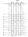
- - les Figures 7, 8 et 9 sont des chronogrammes montrant l'évolution en fonction du temps des tensions qui apparaissent aux points identifiés par les chiffres 1 à 10 sur les Figures 4, 5 et 6, respectivement en cas de détection d'un courant magnétisant en régime transitoire, d'un courant de court-circuit en régime permanent et d'un courant de court-circuit en régime asymétrique.
- Avant de décrire le dispositif, on rappellera son principe de fonctionnement en se reportant à la Figure 2. Le dispositif détecte, à l'instant t0, le dépassement de la valeur de seuil ou de consigne s par l'intensité du courant. Cet instant t0 marque le début d'une temporisation 1/2(T+ Δ T), T étant la période nominale et AT un intervalle de temps qui sera habituellement choisi à une valeur égale à 10% environ de la période. Dans ces conditions, la durée de la temporisation sera de 11 ms pour un réseau à 50 Hz où, en régime établi, on retrouve la même amplitude en valeur absolue toutes les 10 ms. Dans le cas d'un courant de court-circuit du genre montré en Figure 2, où les alternances sont symétriques, on se trouve dans des conditions idéales d'enclenchement et le dispositif fonctionnera 11 ms après avoir détecté un premier dépassement du seuil.
- Si le rapport entre le courant de défaut et la valeur efficace du courant de seuil est suffisamment élevé (>2), le dispositif fonctionne aussi rapidement. Par contre, si ce rapport est inférieur à 2, son fonctionnement pourra être retardé de quelques périodes et dépendra aussi de la constante de temps de l'installation (un L/R faible entraîne un fonctionnement plus rapide. Dans la pratique, on constate que l'allongement du temps de réponse ne devient notable que lorsque la valeur efficace du courant de défaut est très peu supérieure à la valeur de seuil, ce qui représente un inconvénient mineur, le niveau de protection étant bas. Dès que le rapport entre la valeur efficace du courant de défaut et la valeur efficace du courant de seuil dépasse 1,5, le temps de réponse redescend à une valeur de l'ordre de 15 ms pour un courant à 50 Hz.
- Le dispositif montré en Figure 4 sous forme de synoptique et dont un mode de réalisation, constitué en éléments statiques alimentés en tensions de +15 V et -15 V, est donné en Figure 5, comporte un élément d'entrée constitué par un circuit de détection et de redressement 12 qui reçoit un courant d'entrée d'un transformateur de courant monté sur la ligne à surveiller. Ce détecteur 12 comporte un amplificateur opérationnel 13 monté en différentiel et prévu pour fournir un signal de sortie pendant les intervalles de temps où le courant dans la ligne à surveiller dépasse une valeur de seuil ajustable à l'aide d'un potentiomètre 14 (Figure 6A). Le seuil de tension choisi sera généralement très faible, typiquement compris entre 0 et 1 V. En conséquence, le circuit de redressement associé doit être suffisamment élaboré pour que la tension directe des diodes redresseuses n'introduise pas d'erreur.
- On peut en particulier utiliser le montage montré en Figure 6A, à deux branches comprenant chacune une diode 16.
- Le circuit 12 redresseur et détecteur attaque un circuit de détection complémenté sous forme logique 18 fournissant alternativement une tension de sortie nulle ou égale à la tension d'alimentation (+15 V dans le cas illustré), mais complémentaire. Un circuit inverseur 20 situé à la sortie, comportant comme le précédent un transistor alternativement bloqué et saturé, permet de fournir sur sa sortie un signal logique de polarité adaptée à l'attaque d'un circuit mémoire 22. Ce circuit est encore réalisé à l'aide de transistors travaillant alternativement au blocage et à la saturation, par exemple des transistors NPN de type 2N 2221A montés en bascule. Cette mémoire de verrouillage 22 attaque à son tour un temporisateur 24 de durée 1/2T+AT. Ce temporisateur 24 peut avoir la constitution montrée en Figure 6B et comporter un transistor 18 qui, selon qu'il est conducteur ou bloqué, court- circuite le condensateur 20 ou permet sa charge à courant constant par l'intermédiaire d'un second transistor 22. Pour avoir par exemple une tension de 4 V aux bornes du condensateur 20, on adoptera une résistance 24 dans le circuit de charge, de 120 kOhm. Un potentiomètre 26 sera généralement placé dans le circuit de décharge du condensateur 20, pour éviter l'oscillation de transfert des charges. L'amplificateur opérationnel de sortie 30, ayant une tension Zener de 5,1 V'par exemple, passe de l'état -15 V à l'état +15 V dès que la tension aux bornes du condensateur 20 prend une valeur supérieure à une tension de référence ajustable à l'aide d'un potentiomètre 32.
- Le temporisateur 24 et le détecteur 20 attaquent un circuit ET 34 constitué par deux montages similaires à ceux adoptés pour les circuits 18 et 20. Le transistor 36 de sortie de ce circuit ET est alternativement bloqué et saturé. La sortie du circuit ET 36 est ramenée par un conducteur 38 à l'entrée de remise à zéro de la mémoire 22.
- La partie du dispositif constituée des circuits 20, 22, 24 et 34 peut être regardée comme destinée à assurer la discrimination. Le relais électromagnétique de sortie 40 destiné à effectuer le déclenchement est commandé par une seconde branche qui comprend un circuit de temporisation d'entrée 42 identique au circuit 24 mais avec une temporisation T/2, et d'un circuit de test 44 formé par un circuit ET ayant la même constitution que le circuit 34. Ce circuit ET 44 reçoit le signal direct provenant du circuit 18, avant temporisation, par un conducteur 46, et le signal de sortie du temporisateur 24, par un conducteur 50. Le circuit temporisé 42 a pour rôle de commander la remise à zéro d'une mémoire 52, identique à la mémoire 22, par un conducteur 54. Enfin, la sortie de la mémoire attaque le relais 40 par l'intermédiaire d'un transistor de commutation 56.
- Le fonctionnement du dispositif lors d'un courant de court-circuit en régime permanent, c'est-à-dire dans le cas le plus favorable, est illustré sur la Figure 8. Les lignes situées de part et d'autre de l'origine de la trace déterminent le point de consigne de la protection.
- A l'instant to où le courant dépasse pour la première fois le seuil s, il y a inversion des sorties des détecteurs 18 et 20 (lignes 1 et 2). Le changement de niveau logique au point 2 s'inscrit en mémoire 22 à l'instant t0 (ligne 3). Le changement de niveau à la sortie de la mémoire 3 provoque la charge à courant constant du condensateur 20 du temporisateur 24, dont le seuil de basculement est choisi pour correspondre à une durée de temporisation 1/2 T+ AT = 11 ms. En conséquence, la sortie du temporisateur 24 change de niveau logique à l'instant t0+ 11 ms. Entre temps, la sortie des circuits 18 et 20 est revenue dans son état initial pendant le laps de temps au cours duquel la valeur du courant est inférieure au seuil, puis s'est à nouveau inversée, de sorte qu'à aucun moment la porte ET 34 n'a vu ses deux entrées excitées. Elle ne fournit donc pas de sortie de retour à zéro sur la ligne 38.
- Parallèlement, le temporisateur 42, de durée T/2 = 10 ms s'est trouvé mis en route à l'instant t0. Mais la durée de charge du condensateur 20 de ce circuit 42 se limite à l'intervalle de temps pendant lequel le courant est inférieur au seuil (ligne 7). En conséquence, le circuit 42 ne peut à aucun moment fournir un signal de remise à zéro à la mémoire 52 et il en sera de même lors des alternances suivantes. A la première alternance qui suit celle au cours de laquelle le courant a dépassé le seuil, à l'instant t01/2T + ΔT, le circuit ET 44 reçoit des signaux sur ses deux entrées, en provenance des points 1 et 5 (ligne 9) et excite le relais 40. Le déclenchement intervient et est maintenu jusqu'à l'élimination du défaut +T/2.
- Dans le cas, au contraire, d'un courant magnétisant en régime transitoire, ayant l'allure montrée sur la ligne du haut de la Figuré 7, il y a remise à zéro de la mémoire 22 à l'instant t0+1/2T+ ΔT, comme le montre la ligne 3, à 1'apparition d'une impulsion de sortie du circuit ET 34 (ligne 6). A aucun moment il n'y a inscription dans la mémoire 52, le circuti ET 44 ne fournissant pas de sortie (ligne 9) du fait que ses deux entrées ne sont jamais simultanément excitées. En effet, un signal de détection n'apparaît à la sortie du détecteur (ligne 1) qu'à chaque alternance de courant magnétisant et le signal de sortie du temporisateur 24 (ligne 5) n'apparaft qu'après la fin de cette alternance.
- Enfin, en cas de courant de court-circuit en régime asymétrique, on voit que, même pour une forte asymétrie, il y a encore inscription en mémoire 52 sans remise à zéro même pour une forte composante de courant magnétisant.
Claims (5)
Applications Claiming Priority (2)
| Application Number | Priority Date | Filing Date | Title |
|---|---|---|---|
| FR8312264 | 1983-07-25 | ||
| FR8312264A FR2550024B1 (fr) | 1983-07-25 | 1983-07-25 | Dispositif de protection a surintensite de courant |
Publications (2)
| Publication Number | Publication Date |
|---|---|
| EP0133128A1 true EP0133128A1 (fr) | 1985-02-13 |
| EP0133128B1 EP0133128B1 (fr) | 1987-04-15 |
Family
ID=9291087
Family Applications (1)
| Application Number | Title | Priority Date | Filing Date |
|---|---|---|---|
| EP84401561A Expired EP0133128B1 (fr) | 1983-07-25 | 1984-07-25 | Dispositif de protection à surintensité de courant |
Country Status (6)
| Country | Link |
|---|---|
| US (1) | US4697218A (fr) |
| EP (1) | EP0133128B1 (fr) |
| JP (1) | JPS6070924A (fr) |
| CA (1) | CA1211199A (fr) |
| DE (1) | DE3463204D1 (fr) |
| FR (1) | FR2550024B1 (fr) |
Cited By (3)
| Publication number | Priority date | Publication date | Assignee | Title |
|---|---|---|---|---|
| AU588402B2 (en) * | 1986-11-26 | 1989-09-14 | Gosudarstvenny Nauchno-Issledovatelsky Energetichesky Institut Imeni G.M. Krzhizhanovskogo | Device for surge directional protection of transmission line employing carrier-current relaying |
| EP0455314A3 (en) * | 1986-09-30 | 1992-01-08 | Electricity Association Services Limited | Remote protection of three phase distribution transformers |
| EP0453196A3 (en) * | 1990-04-19 | 1993-03-03 | General Electric Company | Transformer differential relay |
Families Citing this family (38)
| Publication number | Priority date | Publication date | Assignee | Title |
|---|---|---|---|---|
| US5208542A (en) * | 1991-03-28 | 1993-05-04 | Eaton Corporation | Timing window arc detection |
| US5185685A (en) * | 1991-03-28 | 1993-02-09 | Eaton Corporation | Field sensing arc detection |
| US5185686A (en) * | 1991-03-28 | 1993-02-09 | Eaton Corporation | Direction sensing arc detection |
| US5185687A (en) * | 1991-03-28 | 1993-02-09 | Eaton Corporation | Chaos sensing arc detection |
| US5185684A (en) * | 1991-03-28 | 1993-02-09 | Eaton Corporation | Frequency selective arc detection |
| US5173848A (en) * | 1991-09-06 | 1992-12-22 | Roof Richard W | Motor controller with bi-modal turnoff circuits |
| US5434509A (en) * | 1992-07-30 | 1995-07-18 | Blades; Frederick K. | Method and apparatus for detecting arcing in alternating-current power systems by monitoring high-frequency noise |
| US5432455A (en) * | 1992-07-30 | 1995-07-11 | Blades; Frederick K. | Method and apparatus for detecting arcing in alternating current power systems by monitoring high-frequency noise |
| US5729145A (en) * | 1992-07-30 | 1998-03-17 | Siemens Energy & Automation, Inc. | Method and apparatus for detecting arcing in AC power systems by monitoring high frequency noise |
| US5452223A (en) * | 1993-08-20 | 1995-09-19 | Eaton Corporation | Arc detection using current variation |
| US6377427B1 (en) | 1995-03-13 | 2002-04-23 | Square D Company | Arc fault protected electrical receptacle |
| US5825598A (en) * | 1997-02-11 | 1998-10-20 | Square D Company | Arcing fault detection system installed in a panelboard |
| US6313641B1 (en) | 1995-03-13 | 2001-11-06 | Square D Company | Method and system for detecting arcing faults and testing such system |
| US6313642B1 (en) | 1995-03-13 | 2001-11-06 | Square D Company | Apparatus and method for testing an arcing fault detection system |
| US6259996B1 (en) | 1998-02-19 | 2001-07-10 | Square D Company | Arc fault detection system |
| US6452767B1 (en) | 1995-03-13 | 2002-09-17 | Square D Company | Arcing fault detection system for a secondary line of a current transformer |
| US6246556B1 (en) | 1995-03-13 | 2001-06-12 | Square D Company | Electrical fault detection system |
| US6242993B1 (en) | 1995-03-13 | 2001-06-05 | Square D Company | Apparatus for use in arcing fault detection systems |
| US6034611A (en) * | 1997-02-04 | 2000-03-07 | Square D Company | Electrical isolation device |
| US6532424B1 (en) | 1995-03-13 | 2003-03-11 | Square D Company | Electrical fault detection circuit with dual-mode power supply |
| US5682101A (en) | 1995-03-13 | 1997-10-28 | Square D Company | Arcing fault detection system |
| US5590012A (en) * | 1995-03-30 | 1996-12-31 | Siemens Energy & Automation, Inc. | Electric arc detector sensor circuit |
| US5834940A (en) * | 1996-09-24 | 1998-11-10 | Brooks; Stanley J. | Arcing fault detector testing and demonstration system |
| US5847913A (en) * | 1997-02-21 | 1998-12-08 | Square D Company | Trip indicators for circuit protection devices |
| US5946179A (en) * | 1997-03-25 | 1999-08-31 | Square D Company | Electronically controlled circuit breaker with integrated latch tripping |
| US5839092A (en) * | 1997-03-26 | 1998-11-17 | Square D Company | Arcing fault detection system using fluctuations in current peaks and waveforms |
| US6621669B1 (en) | 1998-02-19 | 2003-09-16 | Square D Company | Arc fault receptacle with a feed-through connection |
| US6567250B1 (en) | 1998-02-19 | 2003-05-20 | Square D Company | Arc fault protected device |
| US6477021B1 (en) | 1998-02-19 | 2002-11-05 | Square D Company | Blocking/inhibiting operation in an arc fault detection system |
| US6625550B1 (en) | 1998-02-19 | 2003-09-23 | Square D Company | Arc fault detection for aircraft |
| US6782329B2 (en) | 1998-02-19 | 2004-08-24 | Square D Company | Detection of arcing faults using bifurcated wiring system |
| US6275044B1 (en) | 1998-07-15 | 2001-08-14 | Square D Company | Arcing fault detection system |
| DE10117372B4 (de) * | 2001-04-06 | 2006-11-09 | Siemens Ag | Schutzeinrichtung, Schutzanordnung und Schutzverfahren für eine elektrische Leitung |
| US7151656B2 (en) | 2001-10-17 | 2006-12-19 | Square D Company | Arc fault circuit interrupter system |
| US7068480B2 (en) | 2001-10-17 | 2006-06-27 | Square D Company | Arc detection using load recognition, harmonic content and broadband noise |
| US7136265B2 (en) | 2001-10-17 | 2006-11-14 | Square D Company | Load recognition and series arc detection using bandpass filter signatures |
| US7253637B2 (en) | 2005-09-13 | 2007-08-07 | Square D Company | Arc fault circuit interrupter system |
| US9551751B2 (en) | 2011-06-15 | 2017-01-24 | Ul Llc | High speed controllable load |
Citations (4)
| Publication number | Priority date | Publication date | Assignee | Title |
|---|---|---|---|---|
| DE1815200A1 (de) * | 1967-12-22 | 1969-07-24 | Elin Union Ag | Induktive Einschaltstroeme von sonstigen UEberstroemen unterscheidende Schutzeinrichtung |
| DE2334165A1 (de) * | 1973-07-05 | 1975-01-23 | Hartmann & Braun Ag | Schaltungsanordnung zur unterscheidung von kurzschluss- und einschaltstroemen |
| FR2239791A1 (en) * | 1973-08-03 | 1975-02-28 | Siemens Ag | Determination of faults in electrical power transmission links - by monitoring during selected intervals in each half cycle |
| DE2446447A1 (de) * | 1974-09-28 | 1976-04-08 | Deutsche Bundesbahn | Verfahren zur erfassung und auswertung der scheitelwertzunahme eines wechselstromes |
Family Cites Families (4)
| Publication number | Priority date | Publication date | Assignee | Title |
|---|---|---|---|---|
| CH619569A5 (fr) * | 1976-12-02 | 1980-09-30 | Bbc Brown Boveri & Cie | |
| US4255774A (en) * | 1979-03-16 | 1981-03-10 | General Electric Company | Static instantaneous overcurrent relay with low transient overreach |
| US4423458A (en) * | 1982-04-05 | 1983-12-27 | Siemens-Allis, Inc. | Signal processing system for overload relay or the like |
| US4432031A (en) * | 1982-05-03 | 1984-02-14 | General Electric Company | Method for overcurrent protection |
-
1983
- 1983-07-25 FR FR8312264A patent/FR2550024B1/fr not_active Expired
-
1984
- 1984-07-24 US US06/633,882 patent/US4697218A/en not_active Expired - Fee Related
- 1984-07-25 DE DE8484401561T patent/DE3463204D1/de not_active Expired
- 1984-07-25 JP JP59155130A patent/JPS6070924A/ja active Pending
- 1984-07-25 EP EP84401561A patent/EP0133128B1/fr not_active Expired
- 1984-07-25 CA CA000459699A patent/CA1211199A/fr not_active Expired
Patent Citations (4)
| Publication number | Priority date | Publication date | Assignee | Title |
|---|---|---|---|---|
| DE1815200A1 (de) * | 1967-12-22 | 1969-07-24 | Elin Union Ag | Induktive Einschaltstroeme von sonstigen UEberstroemen unterscheidende Schutzeinrichtung |
| DE2334165A1 (de) * | 1973-07-05 | 1975-01-23 | Hartmann & Braun Ag | Schaltungsanordnung zur unterscheidung von kurzschluss- und einschaltstroemen |
| FR2239791A1 (en) * | 1973-08-03 | 1975-02-28 | Siemens Ag | Determination of faults in electrical power transmission links - by monitoring during selected intervals in each half cycle |
| DE2446447A1 (de) * | 1974-09-28 | 1976-04-08 | Deutsche Bundesbahn | Verfahren zur erfassung und auswertung der scheitelwertzunahme eines wechselstromes |
Cited By (4)
| Publication number | Priority date | Publication date | Assignee | Title |
|---|---|---|---|---|
| EP0455314A3 (en) * | 1986-09-30 | 1992-01-08 | Electricity Association Services Limited | Remote protection of three phase distribution transformers |
| AU588402B2 (en) * | 1986-11-26 | 1989-09-14 | Gosudarstvenny Nauchno-Issledovatelsky Energetichesky Institut Imeni G.M. Krzhizhanovskogo | Device for surge directional protection of transmission line employing carrier-current relaying |
| EP0453196A3 (en) * | 1990-04-19 | 1993-03-03 | General Electric Company | Transformer differential relay |
| US5627712A (en) * | 1990-04-19 | 1997-05-06 | General Electric Company | Transformer differential relay |
Also Published As
| Publication number | Publication date |
|---|---|
| DE3463204D1 (en) | 1987-05-21 |
| FR2550024B1 (fr) | 1986-03-14 |
| FR2550024A1 (fr) | 1985-02-01 |
| JPS6070924A (ja) | 1985-04-22 |
| US4697218A (en) | 1987-09-29 |
| EP0133128B1 (fr) | 1987-04-15 |
| CA1211199A (fr) | 1986-09-09 |
Similar Documents
| Publication | Publication Date | Title |
|---|---|---|
| EP0133128B1 (fr) | Dispositif de protection à surintensité de courant | |
| EP0014757B1 (fr) | Circuit détecteur de défauts survenant sur une ligne d'alimentation | |
| EP0407310B1 (fr) | Déclencheur statique comportant un système de désensibilisation de la protection terre | |
| EP0326459B1 (fr) | Déclencheur statique comportant un circuit de déclenchement instantané indépendant de la tension d'alimentation | |
| EP0396477B1 (fr) | Déclencheur statique pour un disjoncteur de protection d'un réseau triphase, permettant la détection du type de défaut | |
| EP0037751B1 (fr) | Déclencheur statique perfectionné pour disjoncteur électrique | |
| EP0019507B1 (fr) | Perfectionnement aux transformateurs capacitifs de tension à sortie électronique | |
| FR2598266A1 (fr) | Declencheur statique instantane pour un disjoncteur limiteur | |
| FR2599870A1 (fr) | Circuit de coupure de surintensite | |
| FR2748611A1 (fr) | Dispositif de coupure a tec de puissance et detection de court-circuit | |
| FR3004019A1 (fr) | Composant de protection contre des surtensions | |
| EP1155488A1 (fr) | Declencheur electronique selectif | |
| EP0060790B1 (fr) | Perfectionnements aux disjoncteurs sensibles aux courants de fuite | |
| FR2547133A1 (fr) | Circuit destine a prevenir une dissipation excessive d'energie dans les dispositifs commutateurs de puissance | |
| CH634182A5 (fr) | Circuit de commande de grille pour convertisseur a thyristors. | |
| EP0466619B1 (fr) | Dispostif de protection contre des surtensions | |
| EP1376843A2 (fr) | Commande d'un thyristor d'un pont redresseur | |
| EP0895671B1 (fr) | Relais statique avec detection d'etat | |
| EP0180487A1 (fr) | Circuit de puissance et dispositif de déclenchement le comportant | |
| FR2823380A1 (fr) | Installation de protection, dispositif de protection et procede de protection pour une ligne electrique | |
| FR2535551A1 (fr) | Dispositif de commutation electronique a faible dissipation de puissance | |
| EP0813283B1 (fr) | Dispositif de protection différentielle immunisé contre les déclenchements intempestifs | |
| EP1083644B1 (fr) | Dispositif de protection terre sensible à des courants d'arc, declencheur et disjoncteur comportant un tel dispositif | |
| EP3627164B1 (fr) | Systeme comprenant un dispositif de commande d'un disjoncteur ultra-rapide d'une installation electrique et procede de test d'un tel systeme | |
| EP0349445B1 (fr) | Dispositif de protection contre les effets des impulsions électromagnétiques nucléaires |
Legal Events
| Date | Code | Title | Description |
|---|---|---|---|
| PUAI | Public reference made under article 153(3) epc to a published international application that has entered the european phase |
Free format text: ORIGINAL CODE: 0009012 |
|
| AK | Designated contracting states |
Designated state(s): BE CH DE GB IT LI |
|
| 17P | Request for examination filed |
Effective date: 19841224 |
|
| 17Q | First examination report despatched |
Effective date: 19860124 |
|
| GRAA | (expected) grant |
Free format text: ORIGINAL CODE: 0009210 |
|
| AK | Designated contracting states |
Kind code of ref document: B1 Designated state(s): BE CH DE GB IT LI |
|
| REF | Corresponds to: |
Ref document number: 3463204 Country of ref document: DE Date of ref document: 19870521 |
|
| ITF | It: translation for a ep patent filed | ||
| PLBE | No opposition filed within time limit |
Free format text: ORIGINAL CODE: 0009261 |
|
| STAA | Information on the status of an ep patent application or granted ep patent |
Free format text: STATUS: NO OPPOSITION FILED WITHIN TIME LIMIT |
|
| 26N | No opposition filed | ||
| PGFP | Annual fee paid to national office [announced via postgrant information from national office to epo] |
Ref country code: CH Payment date: 19910708 Year of fee payment: 8 |
|
| PGFP | Annual fee paid to national office [announced via postgrant information from national office to epo] |
Ref country code: GB Payment date: 19910718 Year of fee payment: 8 |
|
| ITTA | It: last paid annual fee | ||
| PGFP | Annual fee paid to national office [announced via postgrant information from national office to epo] |
Ref country code: BE Payment date: 19910809 Year of fee payment: 8 |
|
| PGFP | Annual fee paid to national office [announced via postgrant information from national office to epo] |
Ref country code: DE Payment date: 19910916 Year of fee payment: 8 |
|
| PG25 | Lapsed in a contracting state [announced via postgrant information from national office to epo] |
Ref country code: GB Effective date: 19920725 |
|
| PG25 | Lapsed in a contracting state [announced via postgrant information from national office to epo] |
Ref country code: LI Effective date: 19920731 Ref country code: CH Effective date: 19920731 Ref country code: BE Effective date: 19920731 |
|
| BERE | Be: lapsed |
Owner name: ELECTRICITE DE FRANCE SERVICE NATIONAL Effective date: 19920731 |
|
| GBPC | Gb: european patent ceased through non-payment of renewal fee |
Effective date: 19920725 |
|
| REG | Reference to a national code |
Ref country code: CH Ref legal event code: PL |
|
| PG25 | Lapsed in a contracting state [announced via postgrant information from national office to epo] |
Ref country code: DE Effective date: 19930401 |