EP0133304B1 - Dispositif pour traiter un substrat mince avec du liquide dans le procédé de passage continu - Google Patents
Dispositif pour traiter un substrat mince avec du liquide dans le procédé de passage continu Download PDFInfo
- Publication number
- EP0133304B1 EP0133304B1 EP19840108901 EP84108901A EP0133304B1 EP 0133304 B1 EP0133304 B1 EP 0133304B1 EP 19840108901 EP19840108901 EP 19840108901 EP 84108901 A EP84108901 A EP 84108901A EP 0133304 B1 EP0133304 B1 EP 0133304B1
- Authority
- EP
- European Patent Office
- Prior art keywords
- substrate
- container
- liquid
- line
- slots
- Prior art date
- Legal status (The legal status is an assumption and is not a legal conclusion. Google has not performed a legal analysis and makes no representation as to the accuracy of the status listed.)
- Expired
Links
- 239000000758 substrate Substances 0.000 title claims description 95
- 238000005112 continuous flow technique Methods 0.000 title 1
- 239000012530 fluid Substances 0.000 title 1
- 239000007788 liquid Substances 0.000 claims description 58
- 238000000034 method Methods 0.000 claims description 15
- 239000000126 substance Substances 0.000 claims description 10
- 238000005530 etching Methods 0.000 claims description 7
- 238000006243 chemical reaction Methods 0.000 claims description 4
- 239000011248 coating agent Substances 0.000 claims description 3
- 238000000576 coating method Methods 0.000 claims description 3
- 238000005238 degreasing Methods 0.000 claims description 3
- 230000002706 hydrostatic effect Effects 0.000 claims description 3
- 239000011261 inert gas Substances 0.000 claims description 3
- 238000009736 wetting Methods 0.000 claims description 3
- 238000007599 discharging Methods 0.000 claims 2
- 238000005086 pumping Methods 0.000 claims 2
- 238000002791 soaking Methods 0.000 claims 1
- WUPHOULIZUERAE-UHFFFAOYSA-N 3-(oxolan-2-yl)propanoic acid Chemical compound OC(=O)CCC1CCCO1 WUPHOULIZUERAE-UHFFFAOYSA-N 0.000 description 10
- 229910052980 cadmium sulfide Inorganic materials 0.000 description 10
- VEXZGXHMUGYJMC-UHFFFAOYSA-N Hydrochloric acid Chemical compound Cl VEXZGXHMUGYJMC-UHFFFAOYSA-N 0.000 description 6
- 239000004065 semiconductor Substances 0.000 description 5
- 238000010924 continuous production Methods 0.000 description 3
- 230000006378 damage Effects 0.000 description 3
- 239000011521 glass Substances 0.000 description 3
- 238000004519 manufacturing process Methods 0.000 description 3
- JPVYNHNXODAKFH-UHFFFAOYSA-N Cu2+ Chemical compound [Cu+2] JPVYNHNXODAKFH-UHFFFAOYSA-N 0.000 description 2
- WLZRMCYVCSSEQC-UHFFFAOYSA-N cadmium(2+) Chemical compound [Cd+2] WLZRMCYVCSSEQC-UHFFFAOYSA-N 0.000 description 2
- 229910001431 copper ion Inorganic materials 0.000 description 2
- OMZSGWSJDCOLKM-UHFFFAOYSA-N copper(II) sulfide Chemical compound [S-2].[Cu+2] OMZSGWSJDCOLKM-UHFFFAOYSA-N 0.000 description 2
- 239000008367 deionised water Substances 0.000 description 2
- 229910021641 deionized water Inorganic materials 0.000 description 2
- 239000010408 film Substances 0.000 description 2
- 239000007789 gas Substances 0.000 description 2
- 238000007654 immersion Methods 0.000 description 2
- 229910052751 metal Inorganic materials 0.000 description 2
- 239000002184 metal Substances 0.000 description 2
- 230000035484 reaction time Effects 0.000 description 2
- XLYOFNOQVPJJNP-UHFFFAOYSA-N water Chemical compound O XLYOFNOQVPJJNP-UHFFFAOYSA-N 0.000 description 2
- GJCXHYNLSNVSQZ-UHFFFAOYSA-L [Cu](Cl)Cl.Cl Chemical compound [Cu](Cl)Cl.Cl GJCXHYNLSNVSQZ-UHFFFAOYSA-L 0.000 description 1
- 239000002253 acid Substances 0.000 description 1
- 230000003247 decreasing effect Effects 0.000 description 1
- 238000010586 diagram Methods 0.000 description 1
- 230000009189 diving Effects 0.000 description 1
- 230000000694 effects Effects 0.000 description 1
- 238000005516 engineering process Methods 0.000 description 1
- 239000000463 material Substances 0.000 description 1
- 238000005554 pickling Methods 0.000 description 1
- 230000001105 regulatory effect Effects 0.000 description 1
- 229910052709 silver Inorganic materials 0.000 description 1
- 239000004332 silver Substances 0.000 description 1
- 230000000087 stabilizing effect Effects 0.000 description 1
- 238000004381 surface treatment Methods 0.000 description 1
- 239000010409 thin film Substances 0.000 description 1
- 238000009827 uniform distribution Methods 0.000 description 1
Images
Classifications
-
- C—CHEMISTRY; METALLURGY
- C23—COATING METALLIC MATERIAL; COATING MATERIAL WITH METALLIC MATERIAL; CHEMICAL SURFACE TREATMENT; DIFFUSION TREATMENT OF METALLIC MATERIAL; COATING BY VACUUM EVAPORATION, BY SPUTTERING, BY ION IMPLANTATION OR BY CHEMICAL VAPOUR DEPOSITION, IN GENERAL; INHIBITING CORROSION OF METALLIC MATERIAL OR INCRUSTATION IN GENERAL
- C23G—CLEANING OR DE-GREASING OF METALLIC MATERIAL BY CHEMICAL METHODS OTHER THAN ELECTROLYSIS
- C23G3/00—Apparatus for cleaning or pickling metallic material
- C23G3/02—Apparatus for cleaning or pickling metallic material for cleaning wires, strips, filaments continuously
-
- B—PERFORMING OPERATIONS; TRANSPORTING
- B05—SPRAYING OR ATOMISING IN GENERAL; APPLYING FLUENT MATERIALS TO SURFACES, IN GENERAL
- B05C—APPARATUS FOR APPLYING FLUENT MATERIALS TO SURFACES, IN GENERAL
- B05C3/00—Apparatus in which the work is brought into contact with a bulk quantity of liquid or other fluent material
- B05C3/02—Apparatus in which the work is brought into contact with a bulk quantity of liquid or other fluent material the work being immersed in the liquid or other fluent material
- B05C3/09—Apparatus in which the work is brought into contact with a bulk quantity of liquid or other fluent material the work being immersed in the liquid or other fluent material for treating separate articles
- B05C3/10—Apparatus in which the work is brought into contact with a bulk quantity of liquid or other fluent material the work being immersed in the liquid or other fluent material for treating separate articles the articles being moved through the liquid or other fluent material
-
- B—PERFORMING OPERATIONS; TRANSPORTING
- B08—CLEANING
- B08B—CLEANING IN GENERAL; PREVENTION OF FOULING IN GENERAL
- B08B11/00—Cleaning flexible or delicate articles by methods or apparatus specially adapted thereto
-
- C—CHEMISTRY; METALLURGY
- C23—COATING METALLIC MATERIAL; COATING MATERIAL WITH METALLIC MATERIAL; CHEMICAL SURFACE TREATMENT; DIFFUSION TREATMENT OF METALLIC MATERIAL; COATING BY VACUUM EVAPORATION, BY SPUTTERING, BY ION IMPLANTATION OR BY CHEMICAL VAPOUR DEPOSITION, IN GENERAL; INHIBITING CORROSION OF METALLIC MATERIAL OR INCRUSTATION IN GENERAL
- C23F—NON-MECHANICAL REMOVAL OF METALLIC MATERIAL FROM SURFACE; INHIBITING CORROSION OF METALLIC MATERIAL OR INCRUSTATION IN GENERAL; MULTI-STEP PROCESSES FOR SURFACE TREATMENT OF METALLIC MATERIAL INVOLVING AT LEAST ONE PROCESS PROVIDED FOR IN CLASS C23 AND AT LEAST ONE PROCESS COVERED BY SUBCLASS C21D OR C22F OR CLASS C25
- C23F1/00—Etching metallic material by chemical means
- C23F1/08—Apparatus, e.g. for photomechanical printing surfaces
Definitions
- the invention relates to a method and a device for treating thin substrates with liquid according to the preambles of claims 1 and 7.
- EP-A-0 032 530 describes a device for treating plate-shaped objects, such as printed circuit boards, which are guided horizontally through a container filled with liquid. Wipers interact with the objects like rollers. A system for pickling wires, strips or the like in an acid bath can be found in DE-A-17 71 934.
- the object of the present invention is to provide a method and a device for treating substrates with liquid in a continuous process, which ensures that a uniform treatment of the surface takes place even with short treatment times, without the risk that the substrate during the treatment is in particular mechanically deformed, which would damage the substrate and thus render it unusable.
- a device for treating thin substrate with liquid comprising a container which is preferably rectangular in section, open at the top and closed at the bottom and which has passage slits on two opposite walls for the horizontal or almost horizontal guidance of the substrate in the liquid and is arranged in an overflow vessel, from which a first conduit having a delivery unit emerges, the free end of which opens into the container below the substrate, which is characterized in that the free end is used to adjust the pressure acting on the substrate through the liquid the line is aligned with the underside of the substrate so that there is a second connection between the overflow vessel and the container for the controlled dispensing of liquid into the area of the container above the substrate, that a riser line extends from the container below the substrate eht, which is connected to the container above the substrate and that an overflow line determining the liquid level starts from the container above the substrate.
- a device in which the substrate is subjected to a uniform pressure load during the treatment, which ensures that mechanical deformations cannot occur.
- treating the substrate with the liquid can be referred to as floating with liquid.
- This buoyancy comprises various processes in a continuous process such as wetting, rinsing, degreasing, coating, etching or chemical conversion. Particularly in the case of processes such as rinsing (detachment effects), etching and chemical conversion, contact times that can be precisely observed, which can be in the range of seconds, are required.
- the second line can be branched off from the first line after the conveying unit and have a throttle in the section leading to the container in order to introduce liquid into the container above the substrate in a controlled manner.
- the container is connected via an overflow line which determines the liquid level, into which the riser line opens, to a liquid reservoir which in turn is connected to an overflow vessel on the bottom side.
- a corresponding device ensures that the pressure conditions around the substrate passed through the container are set in such a way that mechanical deformation cannot occur, so that damage to the substrate is excluded.
- gas nozzles are arranged both before the inlet slot and after the outlet slot, above and below the transport plane of the substrate. Inert gas can then be emitted from these gas nozzles over the entire width of the inlet or outlet slot, so that liquid emerging from the slots is pushed back, so that the substrate is essentially no longer exposed to the liquid after leaving the container.
- the through slots of the container are dimensioned so that they are only slightly wider than the substrate thickness.
- the aforementioned guide device which preferably consist of two V-rails, which hold the substrates on both sides and which in turn run in two rails, which lead through the entry and exit slots, the respective slot should only be about 2 mm thicker than the substrates itself.
- the slot length itself results from the depth of the substrates to be treated.
- the liquid portion to be dispensed onto the substrate could also be conducted at an angle deviating from 90 ° to the underside of the substrate, it has proven to be advantageous for the supply line for the surge material to be guided vertically upward into the container, so that the Exit of the liquid portion is also oriented perpendicular or almost perpendicular to the underside of the substrate to be treated.
- the line the free end of which can be provided with slot nozzles for the uniform distribution of the liquid portion on the substrate, can preferably be brought up to 7.5 cm to 4 cm to the transport plane of the substrate.
- the surge intensity itself can be set by the delivery unit arranged in the line, for example a pump.
- the treatment times for thin, fragile substrates can be set such that times in the seconds range as well as in the minutes range result. This essentially depends on the transport speed of the substrate through the container and the dimensioning of the container itself.
- the method is characterized in that the hydrostatic pressure caused by the liquid column above the substrate is equal to or approximately the same as the pressure acting on the underside of the substrate, which is also determined by the proportion of liquid impinging on the underside of the substrate in a controlled manner .
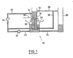
- the device 10 comprises a preferably rectangular section 12 with diametrically arranged inlet and outlet slots 14 and 16 through which the substrate 18 can be guided through the container 12.
- the container 12 is arranged in an overflow vessel 20, from which in turn lines 22 and 24 extend from the bottom.
- the line 24 is connected to a liquid reservoir 26, which in turn is connected to the container 12 via a line 28, the line 28 opening into the container above the slots 14 and 16.
- the line 22 leads back into the container 12 and has a delivery unit such as a pump 30.
- a further line 32 then branches off from the line 22 to the conveying unit 30, which likewise opens into the container 12, likewise above the passage slots 14 and 16.
- a throttle 34 can optionally be arranged in the line 32, around which the line 32 is connected to be able to adjust the liquid to be dispensed into the container 12 to the desired extent.
- a riser 36 extends from the bottom region of the container 12 and opens into the line 28.
- the line 22 is introduced into the container 12 such that the section 38 guided in the container 12 is guided approximately in the longitudinal direction of the container 12 and thus the liquid emerging from the line 22 or 38 vertically or in strikes the substrate 18 guided through the slots 14 and 16 approximately perpendicularly.
- liquid originating from the liquid 26 or the overflow vessel 20 is pumped into the container 12 by means of the delivery unit 30 to such an extent that a liquid level is reached which extends to the connection 28 which specifies the height of the liquid level.
- the line 32 and the riser 36 are filled at the same time.
- the liquid emerging from the passage slots 14 and 16 is taken up by the collecting vessel 20 and fed back to the circuit described above via the line 22 and the conveying unit 30. If a substrate 18 is now passed through the passage slots 14 and 16, the passage gaps 14 and 16 narrow, so that the proportion of the liquid entering the collecting container 20 is reduced.
- the delivery unit 30 can continue to operate with the same delivery rate, there is no one-sided pressure build-up from below the substrate 18 is caused because excess liquid can flow back into the liquid reservoir 26 via the riser pipe 36 and the overflow line 28.
- the liquid level and thus the hydrostatic pressure above the substrate 18 cannot drop due to leakage losses at the slots, since liquid 32 is continuously replenished via the line 32. In this case, however, an impermissible pressure rise cannot occur either, since the liquid level is predetermined by the overflow line 28. If necessary, the inflow into the region of the container 12 above the substrate 18 can be regulated to the required extent by means of the throttle 34.
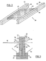
- the substrate 18 does not have to be held mechanically by any transport rollers or by stabilizing or guiding rollers and must be guided through the container 12, in a particularly noteworthy embodiment of the invention, the substrate 18 is received by a holding device 36, as shown in FIG. 2.
- the holding device consists of two rails 42 and 44 which receive the side edges 38 and 40 of the substrate 18 and which have mutually facing concave, preferably V-shaped recesses 46 and 48.
- the side edges 38, 40 are received by these recesses 46, 48, so that now only the rails 42, 44 themselves have to be transported, that is to say in particular through the slots 14 and 16 of the container 12, in order to hold the substrate 18 in the Container 12 to treat existing liquid.
- the slots 14 and 16 are preferably slot nozzles 50, 52, 54 and 56, from which an inert gas can flow out in the direction of the passage slots 14, 16 in order to be able to retain the liquid entrained by the substrate 18.
- the nozzles 50 to 56 are preferably arranged or designed with regard to their outlet opening in such a way that the entire width of the slots 14 and 16 is detected both below and above the substrate 18.
- a corresponding solar cell comprises a substrate support, for example in the form of a glass plate of size 30 x 30 cm 2 with a thickness of approximately 1.5 mm.
- a metal film made of silver, for example, is vapor-deposited onto this glass plate and serves as the first electrical contact.
- a cadmium sulfide layer is then evaporated onto this metal film.
- the surface of the cadmium sulfide layer must be roughened with an aqueous hydrochloric acid.
- the device 10 Since this must be done briefly and very evenly, the device 10 according to the invention is to be used.
- An 18% hydrochloric acid with a temperature of 50 ° C is used as the liquid.
- a container 12 For the substrate having the total thickness of 1.5 mm, a container 12 is used, the through-slots 14 and 16 of which are approximately 3 mm thick.
- the cadmium sulfide layer is then transported through the container 12 in such a way that it points in the direction of the bottom of the container 12.
- the distance between the slots 14 and 16 is chosen to be 4 cm.
- the substrate 18 is then received by a holding device 36, as shown in FIG. 2. With the aid of this holding device 36, the substrate 18 is guided through the slots 14 and 16 and through the liquid.
- the plate is transported through the liquid in about 15 seconds.
- section 38 of line 22 ends approximately 2 cm below the transport plane of substrate 18.
- Section 38 has an approximately 30 cm wide slot nozzle at its end, the slots being approximately 1 mm long are. This selection of the slit nozzle ensures that the surface of the cadmium sulfide is evenly swollen by the aqueous hydrochloric acid. Subsequently, the substrate 18 is transported further in the same way by a corresponding device 10, but in which, instead of the etching solution, deionized water is present for rinsing.
- the cadmium ions in the upper boundary layer of the cadmium sulfide must be exchanged for copper ions in a wet chemical exchange process.
- the substrate with a structured cadmium sulfide surface specified in Example 1 can be transported through a device 10 in which there is a hydrochloric acid-copper chloride solution.
- the dimensions in terms of slot width, slot length, liquid level and distance between the slot nozzle and the lower surface of the substrate can have the same values as in Example 1.
- the device for chemical conversion is located behind the device in which the cadmium sulfide surface has been rinsed with deionized water, so that the treatment of the substrate can be carried out continuously by passing through devices in accordance with the teaching of the invention arranged in a line.
- the speed of the substrate itself does not need to be changed if the reaction time is to be increased or decreased. Rather, in this case it is only necessary to change the distance within the respective container.
- the longer reaction time required for the exchange of cadmium ions by copper ions can be achieved by choosing the depth of the container 12 in the transport direction 6 cm, whereas this was 4 cm in the example 1.
Landscapes
- Chemical & Material Sciences (AREA)
- Chemical Kinetics & Catalysis (AREA)
- General Chemical & Material Sciences (AREA)
- Engineering & Computer Science (AREA)
- Materials Engineering (AREA)
- Mechanical Engineering (AREA)
- Metallurgy (AREA)
- Organic Chemistry (AREA)
- Weting (AREA)
- ing And Chemical Polishing (AREA)
Claims (8)
Applications Claiming Priority (2)
| Application Number | Priority Date | Filing Date | Title |
|---|---|---|---|
| DE19833327753 DE3327753C1 (de) | 1983-08-01 | 1983-08-01 | Vorrichtung und Verfahren zum Behandeln von duennem Substrat mit Fluessigkeit im Durchlaufverfahren |
| DE3327753 | 1983-08-01 |
Publications (2)
| Publication Number | Publication Date |
|---|---|
| EP0133304A1 EP0133304A1 (fr) | 1985-02-20 |
| EP0133304B1 true EP0133304B1 (fr) | 1987-04-29 |
Family
ID=6205492
Family Applications (1)
| Application Number | Title | Priority Date | Filing Date |
|---|---|---|---|
| EP19840108901 Expired EP0133304B1 (fr) | 1983-08-01 | 1984-07-27 | Dispositif pour traiter un substrat mince avec du liquide dans le procédé de passage continu |
Country Status (2)
| Country | Link |
|---|---|
| EP (1) | EP0133304B1 (fr) |
| DE (1) | DE3327753C1 (fr) |
Cited By (1)
| Publication number | Priority date | Publication date | Assignee | Title |
|---|---|---|---|---|
| DE4121079A1 (de) * | 1991-06-26 | 1993-01-07 | Schmid Gmbh & Co Geb | Vorrichtung zum behandeln von plattenfoermigen gegenstaenden |
Families Citing this family (2)
| Publication number | Priority date | Publication date | Assignee | Title |
|---|---|---|---|---|
| FR2629272B1 (fr) * | 1988-03-22 | 1990-11-09 | Bull Sa | Support de circuit integre de haute densite et appareil d'etamage selectif des conducteurs du support |
| WO1996026052A1 (fr) * | 1995-02-24 | 1996-08-29 | New Zealand Forest Research Institute Limited | Appareil pour le traitement d'un materiau |
Family Cites Families (5)
| Publication number | Priority date | Publication date | Assignee | Title |
|---|---|---|---|---|
| DE1771934A1 (de) * | 1968-08-01 | 1972-01-05 | Moehl & Co Kg | Anlage zum Beizen von Draehten,Baendern od.dgl. |
| DE2102678C3 (de) * | 1971-01-21 | 1975-05-15 | Robert Bosch Gmbh, 7000 Stuttgart | Einrichtung zum Aufbringen von feinen Teilchen aus einem Aerosol |
| DE2337280A1 (de) * | 1973-07-23 | 1975-02-13 | Gogas Goch & Co | Reinigungsbad fuer plattenfoermige erzeugnisse |
| CA1114770A (fr) * | 1979-07-18 | 1981-12-22 | Anthony J. Last | Traitement des tissus aux ultrasons |
| DE3001726C2 (de) * | 1980-01-18 | 1984-08-09 | Gebr. Schmid GmbH & Co, 7290 Freudenstadt | Vorrichtung zum Behandeln einer Leiterplatte |
-
1983
- 1983-08-01 DE DE19833327753 patent/DE3327753C1/de not_active Expired
-
1984
- 1984-07-27 EP EP19840108901 patent/EP0133304B1/fr not_active Expired
Cited By (1)
| Publication number | Priority date | Publication date | Assignee | Title |
|---|---|---|---|---|
| DE4121079A1 (de) * | 1991-06-26 | 1993-01-07 | Schmid Gmbh & Co Geb | Vorrichtung zum behandeln von plattenfoermigen gegenstaenden |
Also Published As
| Publication number | Publication date |
|---|---|
| DE3327753C1 (de) | 1985-05-09 |
| EP0133304A1 (fr) | 1985-02-20 |
Similar Documents
| Publication | Publication Date | Title |
|---|---|---|
| DE2455629C3 (de) | Verfahren zum Aufbringen einer Lötmittelschicht auf eine Fläche einer gedruckten Schaltungsplatte oder eines ähnlichen Körpers und Anordnung zur Durchführung des Verfahrens | |
| DE69317703T2 (de) | Vorrichtung und Verfahren zur Behandlung mit Flüssigkeit | |
| EP1733418B1 (fr) | Procede de traitement de surfaces de substrats | |
| DE60036925T2 (de) | Vorrichtung zur Oberflächenbehandlung von Blattmaterial | |
| EP0059787B1 (fr) | Appareil pour couvrir d'une couche mince des pièces électroconductrices composées de bandes, de rubans ou analogues pour un procédé éléctrolytrique en continu | |
| DE2411854B2 (de) | Vorrichtung zum Aufbringen von geschmolzenem Lötmittel auf gedruckte Schaltungsplatten | |
| EP1051886A2 (fr) | Dispositif de traitement electrolytique de carte de circuits et de feuilles conductrices | |
| DE69328328T2 (de) | Verfahren und Gerät zur Flüssigbehandlung | |
| EP0039876A1 (fr) | Dispositif pour le traitement liquide de couches photographiques | |
| DE1652329A1 (de) | Verfahren und Vorrichtung zur Aufbringung einer Fluessigkeit auf einer Oberflaeche | |
| DE3141250A1 (de) | Verfahren und vorrichtung zur fortlaufenden bearbeitung von gedruckten leiterplatten | |
| DE69408490T2 (de) | Vorrichtung zur Behandlung von Gegenständen mit Flüssigkeiten | |
| EP0133304B1 (fr) | Dispositif pour traiter un substrat mince avec du liquide dans le procédé de passage continu | |
| DE3924263A1 (de) | Verfahren und vorrichtung zum elektrolytischen entfernen von schutzschichten von einem metallagensubstrat | |
| DE102014117276A1 (de) | Verfahren und Vorrichtung zur unterseitigen Behandlung eines Substrats | |
| DE3040503C2 (fr) | ||
| EP0196420B1 (fr) | Cellule électrolytique pour le traitement des bandes métalliques à grande vitesse | |
| DE19633797B4 (de) | Vorrichtung zum Galvanisieren von elektronischen Leiterplatten oder dergleichen | |
| WO2020157229A1 (fr) | Dispositif et procédé de traitement de plaquettes | |
| DE3935831A1 (de) | Anlage zur herstellung von durchkontaktierten leiterplatten und multilayern | |
| DE1621626B1 (de) | Verfahren und vorrichtung zur kontinuierlichen oberflaechenbehandlung der kantenbereiche von metallblech | |
| WO2012113364A1 (fr) | Procédé de traitement d'un objet, notamment d'un substrat de cellule solaire, et dispositif permettant de réaliser ce procédé | |
| EP0142010A1 (fr) | Procédé et appareil pour le dépôt électrolytique de métaux | |
| DE3320787C2 (fr) | ||
| DE4223542A1 (de) | Vorrichtung zur Behandlung von Leiterplatten mit einer Behandlungsflüssigkeit |
Legal Events
| Date | Code | Title | Description |
|---|---|---|---|
| PUAI | Public reference made under article 153(3) epc to a published international application that has entered the european phase |
Free format text: ORIGINAL CODE: 0009012 |
|
| 17P | Request for examination filed |
Effective date: 19841210 |
|
| AK | Designated contracting states |
Designated state(s): BE FR GB IT NL |
|
| 17Q | First examination report despatched |
Effective date: 19860314 |
|
| GRAA | (expected) grant |
Free format text: ORIGINAL CODE: 0009210 |
|
| AK | Designated contracting states |
Kind code of ref document: B1 Designated state(s): BE FR GB IT NL |
|
| ITF | It: translation for a ep patent filed | ||
| ET | Fr: translation filed | ||
| PLBE | No opposition filed within time limit |
Free format text: ORIGINAL CODE: 0009261 |
|
| STAA | Information on the status of an ep patent application or granted ep patent |
Free format text: STATUS: NO OPPOSITION FILED WITHIN TIME LIMIT |
|
| 26N | No opposition filed | ||
| PGFP | Annual fee paid to national office [announced via postgrant information from national office to epo] |
Ref country code: BE Payment date: 19890727 Year of fee payment: 6 |
|
| PGFP | Annual fee paid to national office [announced via postgrant information from national office to epo] |
Ref country code: NL Payment date: 19890731 Year of fee payment: 6 |
|
| PG25 | Lapsed in a contracting state [announced via postgrant information from national office to epo] |
Ref country code: BE Effective date: 19900731 |
|
| BERE | Be: lapsed |
Owner name: NUKEM G.M.B.H. Effective date: 19900731 |
|
| PG25 | Lapsed in a contracting state [announced via postgrant information from national office to epo] |
Ref country code: NL Effective date: 19910201 |
|
| NLV4 | Nl: lapsed or anulled due to non-payment of the annual fee | ||
| PGFP | Annual fee paid to national office [announced via postgrant information from national office to epo] |
Ref country code: GB Payment date: 19930716 Year of fee payment: 10 |
|
| PGFP | Annual fee paid to national office [announced via postgrant information from national office to epo] |
Ref country code: FR Payment date: 19930729 Year of fee payment: 10 |
|
| ITTA | It: last paid annual fee | ||
| PG25 | Lapsed in a contracting state [announced via postgrant information from national office to epo] |
Ref country code: GB Effective date: 19940727 |
|
| GBPC | Gb: european patent ceased through non-payment of renewal fee |
Effective date: 19940727 |
|
| PG25 | Lapsed in a contracting state [announced via postgrant information from national office to epo] |
Ref country code: FR Effective date: 19950331 |
|
| REG | Reference to a national code |
Ref country code: FR Ref legal event code: ST |