EP0133397A1 - Datenendstation für die Programmherstellung für eine speicherprogrammierbare Steuerung - Google Patents
Datenendstation für die Programmherstellung für eine speicherprogrammierbare Steuerung Download PDFInfo
- Publication number
- EP0133397A1 EP0133397A1 EP84401531A EP84401531A EP0133397A1 EP 0133397 A1 EP0133397 A1 EP 0133397A1 EP 84401531 A EP84401531 A EP 84401531A EP 84401531 A EP84401531 A EP 84401531A EP 0133397 A1 EP0133397 A1 EP 0133397A1
- Authority
- EP
- European Patent Office
- Prior art keywords
- keys
- screen
- terminal
- keyboard
- mode
- Prior art date
- Legal status (The legal status is an assumption and is not a legal conclusion. Google has not performed a legal analysis and makes no representation as to the accuracy of the status listed.)
- Granted
Links
Images






Classifications
-
- G—PHYSICS
- G05—CONTROLLING; REGULATING
- G05B—CONTROL OR REGULATING SYSTEMS IN GENERAL; FUNCTIONAL ELEMENTS OF SUCH SYSTEMS; MONITORING OR TESTING ARRANGEMENTS FOR SUCH SYSTEMS OR ELEMENTS
- G05B19/00—Program-control systems
- G05B19/02—Program-control systems electric
- G05B19/04—Program control other than numerical control, i.e. in sequence controllers or logic controllers
- G05B19/05—Programmable logic controllers, e.g. simulating logic interconnections of signals according to ladder diagrams or function charts
- G05B19/056—Programming the PLC
-
- G—PHYSICS
- G05—CONTROLLING; REGULATING
- G05B—CONTROL OR REGULATING SYSTEMS IN GENERAL; FUNCTIONAL ELEMENTS OF SUCH SYSTEMS; MONITORING OR TESTING ARRANGEMENTS FOR SUCH SYSTEMS OR ELEMENTS
- G05B2219/00—Program-control systems
- G05B2219/10—Plc systems
- G05B2219/13—Plc programming
- G05B2219/13041—Display ladder or logic diagram, mnemonics, switch between two display
-
- Y—GENERAL TAGGING OF NEW TECHNOLOGICAL DEVELOPMENTS; GENERAL TAGGING OF CROSS-SECTIONAL TECHNOLOGIES SPANNING OVER SEVERAL SECTIONS OF THE IPC; TECHNICAL SUBJECTS COVERED BY FORMER USPC CROSS-REFERENCE ART COLLECTIONS [XRACs] AND DIGESTS
- Y10—TECHNICAL SUBJECTS COVERED BY FORMER USPC
- Y10S—TECHNICAL SUBJECTS COVERED BY FORMER USPC CROSS-REFERENCE ART COLLECTIONS [XRACs] AND DIGESTS
- Y10S715/00—Data processing: presentation processing of document, operator interface processing, and screen saver display processing
- Y10S715/961—Operator interface with visual structure or function dictated by intended use
- Y10S715/965—Operator interface with visual structure or function dictated by intended use for process control and configuration
- Y10S715/97—Instrumentation and component modelling, e.g. interactive control panel
Definitions
- the present invention relates to a terminal for the design, programming, start-up and / or maintenance of an automation using a programmable controller.
- a programmable controller usually comprises a determined number of inputs which can be connected to the detection elements (sensors) of the process, a determined number of control outputs intended to be respectively connected to each of the actuators of the process, and a processor to ensure the sequential flow of operations (actuator control) that the process must perform, taking into account the information provided by the detectors.
- This processor therefore involves, to ensure the scheduling of these operations, a specific program of the process that we want to control.
- This program is generally developed on a computer or the like in an appropriate advanced language, then, after processing by the computer (compilation), transcribed in a machine language to obtain an object program directly usable by the automaton.
- This object program can then be transmitted to the PLC directly by a connection provided for this purpose between the computer and the PLC. It can also be stored on a peripheral memory such as, for example a magnetic tape, a floppy disk, or even on a user programmable memory (PROM), for example a programmable erasure memory (EPROM).
- PROM user programmable memory
- EPROM programmable erasure memory
- the automaton must necessarily be equipped with a corresponding reading unit, for example a magnetic tape reader or a floppy disk reader, or even a connector allowing the connection of the programmable memory.
- terminals have already been made comprising a keyboard, a screen and a processor making it possible to define automations by means of diagrams produced on the screen according to a mode of graphic representation identifiable by the processor.
- programming the controller no longer requires extensive computer knowledge.
- the operator is content to draw the diagrams of the automation on the screen, while the processor is responsible for developing the program directly from these diagrams.
- the invention therefore aims to eliminate this drawback. It therefore proposes a terminal which makes it possible to carry out the programming of an automaton by using a graphical representation mode which consists of the combination of the "contact" representation mode and a so-called “sequential" representation mode which is derived from '' an analysis method consisting in breaking down the operation of the machine or process to be automated into a succession of steps and transitions, all linked together. Each step is associated with a list of actions which are executed when this step is active.
- graphic keys can be divided into two separate keyboards, namely a keyboard for the graphical representation mode with contact and a keyboard for sequential graphing.
- these graphic keys are dynamic keys, that is to say keys associated with configurations, symbols and functions which vary according to the context of use of the terminal .
- the processor is designed so as to display on the screen, preferably at the level of its lower line, an area (display line) which makes it possible to identify the functions of each key for a given context of use.
- this display line which is used to represent the graphic symbols assigned to the dynamic keys for the two graphic representation modes previously mentioned, can also be used to display the different "menus” or "submenus” which allow change the terminal from one type of operation to another or from one menu to another.
- the display line displays, for each of the configurations proposed by a specific "menu", a memotechnical preference symbol corresponding to a key.
- the processor can also be designed to divide the terminal screen into five zones, namely, a display zone, an address display strip, an event zone, an automation status zone and the display line previously mentioned.
- the viewing area can be used to display multiple information. It is used in particular for the graphic representation of the automation.
- the status area of the PLC can include the following three indications: RUN (on), STOP (stop), TEST.
- the terminal processor is designed so as to recognize and use the symbols of the "contact" graphical representation mode which are used in particular in the input combinatorial, in the output combinatorial and in the representation receptivity associated with transitions of the graphical representation mode of sequential type. Consequently, the processor can also be designed, without implying significant transformations of the terminal, to allow the realization of automation only using the "contact" representation mode.
- This mode of use can be selected using the "menu" functions assigned to the above dynamic keys.
- the above installation comprises first of all a terminal 1 incorporating in a single housing, a keyboard 2 and a screen with liquid crystal display (LC D.) 3, the contrast of which can be adjusted by a wheel. 4.
- the screen 3 could be independent of the terminal box and could consist of a cathode-ray tube monitor.
- the controller 5 is connected by its inputs to the process detection elements 7 and, by its outputs, to the various controlled elements (actuators) of the process 7. It also includes a connection device for connecting a memory cartridge dead containing the specific program of the automation which ensures the control of the process.
- This cartridge can include one or more memories programmable by the user, for example of the PROM or EPROM type.
- a programmable memory programmer is also incorporated in the terminal so as to allow the transfer of the contents of the terminal's RAM memory into the read-only memory cartridge (programmable) connected to the terminal.
- the display zone 15 comprises, in the "contact" representation mode, four lines of nine input contacts and an output coil.
- the processor of terminal 1 comprises a microprocessor 20, for example an NSC 800 from the National Semiconductor Company or an 8085 from the INTEL Company, from which a data bus 21 and an address bus 22 leave.
- a microprocessor 20 for example an NSC 800 from the National Semiconductor Company or an 8085 from the INTEL Company, from which a data bus 21 and an address bus 22 leave.
- the graphical representation of the contact type uses symbols representative of the input contacts (reference of the inputs I x y, z of the controller) and of the output coils (reference of the outputs O x y, z of the controller).
- the graphical contact representation mode also involves symbols representative of elements having particular functions such as timers, counters, programmers, shift registers, arithmetic or logical operators, etc.
- the parameters relating to these special functions are entered in the terminal immediately after the block, but are not written to the network.
- the process to be automated consists of a machine used for drilling and cutting metal bars.
- the first stage for the development of the automation consists of the assignment of the inputs / outputs of the controller 5 using the addressing mode described above (I xy, z for the inputs, O xy, z for outputs).
- the following table I shows an example of assignment:
- FIG. 6 shows the graphical representation of the contact type of the automation, this representation being executed in manuscript on a form specially designed for this purpose.
- This representation includes four groups of contact lines called networks, which are numbered (001, 002, 003, 004) to the left of the figure.
- a network is a set of one with four parallel contact lines with or without vertical connections between them.
- the control input devices pushbuttons, switches, etc.
- They are all grouped on the left side of the contact lines (test area) and can be a maximum of nine in series per line. They are referenced 1 0.0 to 1 2.0 in this example.
- the control elements are represented in the form of coils, necessarily represented in the right column of the relay diagram, which constitutes the action area. These coils are referenced 0 1.0 to 0 3.1 in this example.
- the timer function (network 003) is represented by a function block with two lines at input and at output.
- a source program is designed in the terminal designed to develop the program of the automaton from the graphical representation mode with contacts. This can for example be achieved by inserting a programming cartridge (ROM, EPROM) in the connection system provided for this purpose. The terminal is then connected to the PLC for online use.
- the third network of the automation shown in Figure 6 includes a block representative of the timer function.
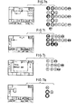
- To create this network first create the circuit located before the block, as shown in Figure 7i. Beforehand, the network label is entered using the (LAB) (0) (0) (3) (ENT) keys; the first contact and its reference are entered using the (%) ( ⁇ ⁇ ) (0) (1) keys (,) (6) (ENT) then call the timer block using the (%) (BLO) (TMN) keys.
- connection of the 2nd input of the timer block is obtained by positioning the cursor, key ( ⁇ ), by introducing the vertical connection, keys (/) ( ⁇ ) and by making the horizontal connection, key (-) (figure 7k ). It then only remains to enter the outputs.
- the terminal has the PLC source program in dynamic memory.
- a bet should be made. to the point of this program in particular by detecting and correcting the errors which may have occurred during the seizure of the networks.
- we return to the first network using the dynamic keys (SCH) (TOP) then we verify that this first network is correct.
- the downstream network is then displayed using the ( ⁇ ) key and so on ... If, for example, an error exists in the 2nd network: a normally open contact has been introduced instead of the normally closed contact 1 0.1 .
- the cursor is then displayed by pressing the ZOOM (ZM) key.
- the tasks are generally carried out in a determined order and are grouped in stages represented by blocks. Each end of operation generally conditions the passage to the next step. This condition is called transition.
- the transitions indicate the possibilities of evolution between stages, a stage can only become active if the previous stage is active. Activating a step deactivates the previous step.
- a stage can succeed several stages in parallel. If these steps are to be triggered simultaneously, there is a divergence in AND ( Figure 8b). If each has its own activation transition, then there is a divergence in OR ( Figure 8c). Likewise, several parallel steps can converge towards a single step. In the case of convergence in AND ( Figure 8d), there is only one common transition between the parallel steps and the next step. For an OR convergence ( Figure 8e) each parallel step has its own transition to the next step. In a complex automation, several sequences or groups of actions can be simultaneous and have independent evolutions. In this case, the sequential diagram will be broken down into several branches.
- the terminal allows the development of programs usable by an automaton by using a graphical representation mode which combines the contact type representation mode with a sequential type graphical representation mode.
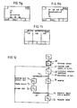
- This mode of graphical representation hereinafter called functional mode, comprises three phases, namely, the combinatorial input (CBI), the sequential phase (SEQ) and the combinatorial output (CBO) ( Figure 9).
- the combinatorial input 60 consists of the phase during which all the safety features of the program are processed such as power cut, watchdog ... and the safety related to the operating modes: manual, automatic etc ... Certain steps may be directly initialized or activated in the event of specific events.
- This phase is programmed in contact graphical representation mode as described above.
- the sequential phase is an essential phase which makes it possible to define the sequence of stages-transitions.
- the graphic representation 61 of this sequential phase is carried out in two stages.
- the stages can be chained, either in linear sequences, or in parallel branches.
- a divergence can initiate a limited number of parallel branches, for example 6.
- the number of divergences and convergences in AND can be limited for example to 16.
- the number of divergences and convergences in OR may not be the subject of a limitation.
- the output combinatorial 64 is a phase during which the actions linked to each step are defined according to the graphical contact representation mode.
- Each step Xi of the sequential graph 62 is associated with one or more contact networks representative of all the actions to be executed during the activity of this step.
- connection screen (fig. 10a) of the type is obtained.
- the display line assigns to the dynamic keys the symbols PRG (program) EXC (Execution) REG (adjustment) TRF (Transfer) DGN (diagnosis) and% (Second function of the dynamic keys (Shift)).
- PRG program
- EXC Execution
- REG adjustment
- TRF Transfer
- DGN diagnosis
- % Second function of the dynamic keys
- the rest of the functional diagram is obtained by moving the cursor down by means of the key (j) which makes it possible to obtain the screen represented in FIG. 11c which makes it possible to define the step and the downstream transition.
- the cursor is then positioned on the downstream step to enter its number using the numeric keys and the validation key (ENT).
- FIG. 11d An example of receptivity has been shown, in broken lines in FIG. 11d.
- the display of the downstream step is obtained by moving the cursor down which causes the appearance of a screen. similar to that shown in Figure llb.
- the capture of linear sequences is thus done by a succession of steps and transitions.
- the user can, according to his preferences, either define the conditions of receptivity of each transition immediately after each step, or define the whole of the automation in sequential representation then make reappear each transition on the screen and then define it in representation contact after pressing the (REC) key.
- a time delay of value "Xi, V" is automatically associated with each step “Xi” when it is active.
- the time base for this time delay is fixed, for example at 1 second.
- the value "Xi, V” can be read by the user or the program to check how long the "Xi” step has been active.
- a step “Xi” remains active after a determined period of time, for example 9999 seconds (2 h 47)
- the current value "Xi, V" automatically returns to 0 and is incremented again.
- the divergences and the convergences in OR are carried out on the screen visualizing a stage between two transitions.
- the divergence in OR is obtained by placing the cursor above the downstream transition then by creating the divergence between two parallel branches by means of the dynamic key ( ) (figure lle).
- the terminal can, for example, enter up to 4 parallel branches.
- the dynamic key ( ) therefore creates a divergence or convergence in AND, with the possibility of multiple (for example triple) juxtaposition.
- the numbers of the stages located downstream of a divergence or upstream of a convergence are entered by moving the cursor horizontally and vertically.
- step "Xi" When the step "Xi" is displayed, it is then possible to search for one of the steps upstream or downstream to this transition. To do this, the cursor is displayed with the Zoom key (ZM) then the cursor is moved to bring it to the desired transition.
- ZM Zoom key
- the dynamic key (REC) displays the contact network of the receptivity associated with the transition, which can be modified like any other contact network.
- the new network is validated with the (ENT) key.
- the insertions of steps and transitions are done graphically on the sequential diagram which can be modified step by step.
- the transitions inserted will first be defined graphically and then on the terminal in contact representation mode, with the dynamic key (REC) on the transition screen (figure llc).
- This direct chain is looped upstream of the first transition 67.
- the circuit comprises, downstream of the second transition 69, a divergence in AND 73 from which a parallel circuit starts comprising a step 74 representative of the rotation and of the advance of the saw 51, a transition 75 (detection of the elapsed time by a time delay) and a step 76 representative of the return of the saw 51.
- This parallel circuit is connected to the main chain, upstream of the transition 71, by means of convergence in AND 77.
- the input combinatorial programming is then called up using the CBI key. We can then enter, in contact representation mode, the networks dealing with all the safety conditions and the operating modes of the program.
- the input combinatorics can comprise only one receptivity (contact) and one action (coil) allowing for example to carry out an emergency stop (coil) in the event of alarm on a detector (contact).
- the first stage XO will be designated by the numbers ⁇ (figure 13a) and is declared stage "initial" with the dynamic key ( ). As previously mentioned, this initial step XO is the step on which the program remains stopped when the PLC is powered up.
- Pressing the dynamic key (REC) displays the symbols used in the "contact" graphic representation mode on the display line of the screen.
- the receptivity associated with the transition Xo / Xl can, for example involve an output coil and two contacts arranged in series, namely, a contact I 0,0 which is conducting when the drill is in the high position and a contact 1 0 , 2 which is on when the saw is in the rear position.
- step X2 The divergence in AND between step X2 and steps X3 and X4 is entered using the key ( ) ( Figure 13e).
- step X5 (figure 13f)
- step X6 (figure 13g)
- step X2 (figure 13h)
- the next phase consists of entering the output combinatorics, which includes six networks in contact type graphical representation mode which each correspond to the actions relating to the six steps of the sequential diagram.
- FIG. 14 shows, in contact type representation mode, the diagram of the combinatorial output of the automation represented in FIG. 5.
- the network bearing the label 003 comprises a contact X3 corresponding to step 70 of the sequential diagram and a coil 01,0 controlling the rise of the drill 48.
- the network bearing the label 004 comprises a contact X4 corresponding to step 74 of the sequential diagram, a coil 01.6 controlling the rotation of the saw 51 and a coil 01.4 controlling the advance of the saw 51.
- the network bearing the label 005 comprises a contact X5 corresponding to step 76 of the sequential diagram and a coil 01.5 controlling the return of the saw 51.
- the network bearing the label 006 comprises a contact X6 corresponding to step 71 of the functional diagram and a coil 04.0 controlling the thrust of the jack 44.
- Entering the output combinatorial is done by first returning to the screen shown in Figure 10d by pressing the CLEAR key twice and then pressing the dynamic CBO key indicated on this screen. A screen is thus obtained allowing entry according to the "contact" type of representation mode.
- An alternative embodiment of the present invention consists in programming graphically only the sequential parts as shown in FIG. 12, then in using the alphanumeric means of the keyboard and the pointing by zooming to program the logical relations defining the equations of state respectively. of each output according to the inputs and other variables that condition it.
- the operator will enter the receptivity associated with the Xo / Xl transition, after pointing it and selecting it by zooming, by using the following keys:
Landscapes
- Physics & Mathematics (AREA)
- General Physics & Mathematics (AREA)
- Engineering & Computer Science (AREA)
- Automation & Control Theory (AREA)
- Programmable Controllers (AREA)
- Input From Keyboards Or The Like (AREA)
- Testing And Monitoring For Control Systems (AREA)
Applications Claiming Priority (2)
| Application Number | Priority Date | Filing Date | Title |
|---|---|---|---|
| FR8312268 | 1983-07-25 | ||
| FR8312268A FR2549983B1 (fr) | 1983-07-25 | 1983-07-25 | Terminal pour l'elaboration de programmes utilisables par un automate programmable |
Publications (2)
| Publication Number | Publication Date |
|---|---|
| EP0133397A1 true EP0133397A1 (de) | 1985-02-20 |
| EP0133397B1 EP0133397B1 (de) | 1987-09-02 |
Family
ID=9291089
Family Applications (1)
| Application Number | Title | Priority Date | Filing Date |
|---|---|---|---|
| EP84401531A Expired EP0133397B1 (de) | 1983-07-25 | 1984-07-20 | Datenendstation für die Programmherstellung für eine speicherprogrammierbare Steuerung |
Country Status (6)
| Country | Link |
|---|---|
| US (1) | US4736340A (de) |
| EP (1) | EP0133397B1 (de) |
| JP (1) | JPH0782368B2 (de) |
| CA (1) | CA1227883A (de) |
| DE (1) | DE3465803D1 (de) |
| FR (1) | FR2549983B1 (de) |
Cited By (3)
| Publication number | Priority date | Publication date | Assignee | Title |
|---|---|---|---|---|
| EP0251699A3 (en) * | 1986-06-24 | 1989-12-20 | Westinghouse Electric Corporation | A logic diagram compiler executor |
| FR2641878A1 (fr) * | 1988-12-28 | 1990-07-20 | Nicolai Jean Pierre | Systeme de controle et de commande par visualisation de synoptiques sur un terminal graphique intelligent d'un procede automatise |
| WO1990015370A1 (en) * | 1989-06-01 | 1990-12-13 | Paul Jonathan Fray | Process control |
Families Citing this family (20)
| Publication number | Priority date | Publication date | Assignee | Title |
|---|---|---|---|---|
| JPS6225417A (ja) * | 1985-07-25 | 1987-02-03 | Canon Inc | 半導体製造装置 |
| JPS6225418A (ja) * | 1985-07-25 | 1987-02-03 | Canon Inc | 半導体製造装置 |
| US4849880A (en) * | 1985-11-18 | 1989-07-18 | John Fluke Mfg. Co., Inc. | Virtual machine programming system |
| JPH0210454A (ja) * | 1988-06-29 | 1990-01-16 | Canon Inc | 電子機器 |
| US5148516A (en) * | 1988-08-30 | 1992-09-15 | Hewlett-Packard Company | Efficient computer terminal system utilizing a single slave processor |
| JP2927484B2 (ja) * | 1989-01-25 | 1999-07-28 | 株式会社日立製作所 | プログラムの自動生成方法及び装置 |
| JPH0658624B2 (ja) * | 1990-03-30 | 1994-08-03 | インターナショナル・ビシネス・マシーンズ・コーポレーション | グラフィカル・ユーザ・インターフェース管理装置 |
| US5168441A (en) * | 1990-05-30 | 1992-12-01 | Allen-Bradley Company, Inc. | Methods for set up and programming of machine and process controllers |
| FR2681160B1 (fr) * | 1991-09-05 | 1995-03-24 | Telemecanique | Dispositif d'entree ou de sortie, notamment pour automate programmable. |
| DE4229710B4 (de) * | 1991-09-09 | 2008-06-05 | Samsung Electronics Co., Ltd. | Digitales Audiodatenspeicherungssystem und damit ausgerüstetes digitales Audio-System |
| JP3100817B2 (ja) * | 1993-12-10 | 2000-10-23 | 三菱電機株式会社 | 制御プログラム設計支援装置 |
| US5862401A (en) * | 1994-10-11 | 1999-01-19 | Crown International, Inc. | Programmable central intelligence controller and distributed intelligence network for analog/digital control systems |
| AU1115400A (en) * | 1998-10-13 | 2000-05-01 | Scientronix, Inc. | System and method for generating a control program |
| US20060190106A1 (en) * | 2001-07-30 | 2006-08-24 | Rockwell Automation Technologies, Inc. | Method for consistent storage of data in an industrial controller |
| US7065415B2 (en) * | 2001-07-30 | 2006-06-20 | Rockwell Automation Technologies, Inc. | Method for consistent storage of data in an industrial controller |
| DE10147166A1 (de) * | 2001-09-25 | 2003-04-24 | Siemens Ag | System und Verfahren zur Programmierung eines Automatisierungssystems basierend auf Impulsdiagrammen |
| US20030066050A1 (en) * | 2001-09-26 | 2003-04-03 | Wang Douglas W. | Method and system for programming devices using finite state machine descriptions |
| JP2004206550A (ja) * | 2002-12-26 | 2004-07-22 | Fanuc Ltd | 数値制御装置 |
| US20060074499A1 (en) * | 2004-10-01 | 2006-04-06 | Rafie Hamidpour | System and method for industrial process control |
| EP1923755A1 (de) * | 2006-11-20 | 2008-05-21 | Siemens Aktiengesellschaft | Verfahren für die gemeinsame Darstellung von Ablaufdiagrammen |
Citations (5)
| Publication number | Priority date | Publication date | Assignee | Title |
|---|---|---|---|---|
| US3964026A (en) * | 1973-05-22 | 1976-06-15 | Nissan Motor Co., Ltd. | Sequence block display system |
| EP0014047A1 (de) * | 1979-01-09 | 1980-08-06 | Westinghouse Electric Corporation | Programmierbares Rechenwerk mit doppeltem Stapler zur Lösung eines Kettendiagramms und Programmierpult dafür |
| DE3222305A1 (de) * | 1981-06-15 | 1982-12-30 | Hitachi, Ltd., Tokyo | Ablaufprogramm-setzgeraet |
| GB2111266A (en) * | 1981-11-18 | 1983-06-29 | Sharp Kk | Programmable electronic calculator |
| EP0089194A2 (de) * | 1982-03-11 | 1983-09-21 | Fanuc Ltd. | Verfahren und Gerät zum Anzeigen von Leiterdiagrammen |
Family Cites Families (6)
| Publication number | Priority date | Publication date | Assignee | Title |
|---|---|---|---|---|
| JPS5644940A (en) * | 1979-09-19 | 1981-04-24 | Seizaburou Sasaki | Program coding unit |
| JPS5769411A (en) * | 1980-10-16 | 1982-04-28 | Toshiba Mach Co Ltd | Collation system for sequence program |
| JPS57143610A (en) * | 1981-03-03 | 1982-09-04 | Mitsubishi Electric Corp | Programming device |
| JPS5885237U (ja) * | 1981-12-04 | 1983-06-09 | オムロン株式会社 | グラフイツク・プログラミング・コンソ−ルユニツト |
| US4570217A (en) * | 1982-03-29 | 1986-02-11 | Allen Bruce S | Man machine interface |
| US4488258A (en) * | 1982-09-20 | 1984-12-11 | Allen-Bradley | Programmable controller with control program comments |
-
1983
- 1983-07-25 FR FR8312268A patent/FR2549983B1/fr not_active Expired
-
1984
- 1984-07-20 EP EP84401531A patent/EP0133397B1/de not_active Expired
- 1984-07-20 DE DE8484401531T patent/DE3465803D1/de not_active Expired
- 1984-07-25 CA CA000459626A patent/CA1227883A/fr not_active Expired
- 1984-07-25 JP JP59155113A patent/JPH0782368B2/ja not_active Expired - Lifetime
- 1984-07-25 US US06/634,245 patent/US4736340A/en not_active Expired - Lifetime
Patent Citations (5)
| Publication number | Priority date | Publication date | Assignee | Title |
|---|---|---|---|---|
| US3964026A (en) * | 1973-05-22 | 1976-06-15 | Nissan Motor Co., Ltd. | Sequence block display system |
| EP0014047A1 (de) * | 1979-01-09 | 1980-08-06 | Westinghouse Electric Corporation | Programmierbares Rechenwerk mit doppeltem Stapler zur Lösung eines Kettendiagramms und Programmierpult dafür |
| DE3222305A1 (de) * | 1981-06-15 | 1982-12-30 | Hitachi, Ltd., Tokyo | Ablaufprogramm-setzgeraet |
| GB2111266A (en) * | 1981-11-18 | 1983-06-29 | Sharp Kk | Programmable electronic calculator |
| EP0089194A2 (de) * | 1982-03-11 | 1983-09-21 | Fanuc Ltd. | Verfahren und Gerät zum Anzeigen von Leiterdiagrammen |
Non-Patent Citations (2)
| Title |
|---|
| BYTE, vol. 8, no. 6, juin 1983, pages 282-286, Byte Publications Inc., New York, US; S. WSZOLA: "NEC PC-8201 portable computer - A new contender with Tandy's model 100" * |
| PATENTS ABSTRACTS OF JAPAN, vol. 6, no. 148 (P-133)[1026], 7 août 1982, page 1026 P 133; & JP - A - 57 69 411 * |
Cited By (3)
| Publication number | Priority date | Publication date | Assignee | Title |
|---|---|---|---|---|
| EP0251699A3 (en) * | 1986-06-24 | 1989-12-20 | Westinghouse Electric Corporation | A logic diagram compiler executor |
| FR2641878A1 (fr) * | 1988-12-28 | 1990-07-20 | Nicolai Jean Pierre | Systeme de controle et de commande par visualisation de synoptiques sur un terminal graphique intelligent d'un procede automatise |
| WO1990015370A1 (en) * | 1989-06-01 | 1990-12-13 | Paul Jonathan Fray | Process control |
Also Published As
| Publication number | Publication date |
|---|---|
| FR2549983B1 (fr) | 1988-03-18 |
| JPH0782368B2 (ja) | 1995-09-06 |
| CA1227883A (fr) | 1987-10-06 |
| DE3465803D1 (en) | 1987-10-08 |
| US4736340A (en) | 1988-04-05 |
| FR2549983A1 (fr) | 1985-02-01 |
| EP0133397B1 (de) | 1987-09-02 |
| JPS6084605A (ja) | 1985-05-14 |
Similar Documents
| Publication | Publication Date | Title |
|---|---|---|
| EP0133397B1 (de) | Datenendstation für die Programmherstellung für eine speicherprogrammierbare Steuerung | |
| US8589874B2 (en) | Visual interface to represent scripted behaviors | |
| JP4888717B2 (ja) | 安全コントローラのプログラム開発支援装置 | |
| FR2559597A1 (fr) | Systeme informatique a ecran sensible au toucher, programmable et intelligent | |
| JP3258379B2 (ja) | メニュー表示装置 | |
| FR2647239A1 (fr) | Procede de generation d'interfaces pour applications-utilisateurs visualisables sur l'ecran d'un systeme informatique et dispositif pour mettre en oeuvre ledit procede | |
| EP0251699B1 (de) | Logikdiagrammübersetzer-Ausführeinheit | |
| FR2607284A1 (fr) | Systeme d'affichage dynamique interactif pour base de connaissances | |
| FR2783455A1 (fr) | Systeme de gestion de processus base sur un processeur offrant des possibilites de programmation intuitive | |
| JP7824004B2 (ja) | コンピュータプログラム、システムおよび方法(ログファイル内のエラーに関連するコード文のブロックの視覚化の生成) | |
| KR20030019427A (ko) | 프리뷰화상의 표시방법 및 프리뷰화상 표시장치 | |
| WO2000072111A2 (fr) | Outil universel de compilation de graphes | |
| FR2508669A1 (fr) | Dispositif logique programmable de prise, traitement et transmission de donnees | |
| EP0331551B1 (de) | Speicherprogrammierbare Steuerung mit strukturierter Programmiersprache | |
| CN113593364A (zh) | 一种积木编程教学指引方法、装置、系统及介质 | |
| FR2461294A1 (fr) | Dispositif de modification de programme de sequence | |
| US5299114A (en) | Sequence program search method | |
| JPS5826031B2 (ja) | 編集処理方式 | |
| BE1006555A6 (fr) | Une methode de production d'un systeme de commande d'affichage d'interface. | |
| JPH0519817A (ja) | シーケンス・プログラムの編集方式 | |
| FR2826746A1 (fr) | Procede et dispositif d'elaboration de programmes d'automatismes | |
| Koutnik | Build Reactive Websites with RxJS: Master Observables and Wrangle Events | |
| FR2569876A1 (fr) | Procede et dispositif de visualisation graphique pour un systeme de commande numerique de machine-outil | |
| JPH0863218A (ja) | 数値制御装置のプログラム構成表示方式 | |
| EP2610743A1 (de) | Simulationsverfahren der Mensch-Maschinen-Schnittstelle eines Geräts |
Legal Events
| Date | Code | Title | Description |
|---|---|---|---|
| PUAI | Public reference made under article 153(3) epc to a published international application that has entered the european phase |
Free format text: ORIGINAL CODE: 0009012 |
|
| 17P | Request for examination filed |
Effective date: 19840723 |
|
| AK | Designated contracting states |
Designated state(s): BE DE FR GB IT NL SE |
|
| 17Q | First examination report despatched |
Effective date: 19861114 |
|
| GRAA | (expected) grant |
Free format text: ORIGINAL CODE: 0009210 |
|
| AK | Designated contracting states |
Kind code of ref document: B1 Designated state(s): BE DE FR GB IT NL SE |
|
| GBT | Gb: translation of ep patent filed (gb section 77(6)(a)/1977) | ||
| REF | Corresponds to: |
Ref document number: 3465803 Country of ref document: DE Date of ref document: 19871008 |
|
| ITF | It: translation for a ep patent filed | ||
| R20 | Corrections of a patent specification |
Effective date: 19871013 |
|
| PLBI | Opposition filed |
Free format text: ORIGINAL CODE: 0009260 |
|
| PLBI | Opposition filed |
Free format text: ORIGINAL CODE: 0009260 |
|
| 26 | Opposition filed |
Opponent name: AEG AKTIENGESELLSCHAFT, BERLIN UND FRANKFURT Effective date: 19880521 |
|
| 26 | Opposition filed |
Opponent name: SIEMENS AKTIENGESELLSCHAFT, BERLIN UND MUENCHEN Effective date: 19880527 Opponent name: AEG AKTIENGESELLSCHAFT, BERLIN UND FRANKFURT Effective date: 19880521 |
|
| NLR1 | Nl: opposition has been filed with the epo |
Opponent name: SIEMENS AKTIENGESELLSCHAFT Opponent name: AEG AKTIENGESELLSCHAFT |
|
| ITTA | It: last paid annual fee | ||
| EAL | Se: european patent in force in sweden |
Ref document number: 84401531.3 |
|
| PLBN | Opposition rejected |
Free format text: ORIGINAL CODE: 0009273 |
|
| STAA | Information on the status of an ep patent application or granted ep patent |
Free format text: STATUS: OPPOSITION REJECTED |
|
| 27O | Opposition rejected |
Effective date: 19941117 |
|
| NLR2 | Nl: decision of opposition | ||
| PGFP | Annual fee paid to national office [announced via postgrant information from national office to epo] |
Ref country code: NL Payment date: 19970625 Year of fee payment: 14 |
|
| PGFP | Annual fee paid to national office [announced via postgrant information from national office to epo] |
Ref country code: GB Payment date: 19970715 Year of fee payment: 14 |
|
| PGFP | Annual fee paid to national office [announced via postgrant information from national office to epo] |
Ref country code: SE Payment date: 19970716 Year of fee payment: 14 |
|
| PGFP | Annual fee paid to national office [announced via postgrant information from national office to epo] |
Ref country code: BE Payment date: 19970812 Year of fee payment: 14 |
|
| PG25 | Lapsed in a contracting state [announced via postgrant information from national office to epo] |
Ref country code: GB Free format text: LAPSE BECAUSE OF NON-PAYMENT OF DUE FEES Effective date: 19980720 |
|
| PG25 | Lapsed in a contracting state [announced via postgrant information from national office to epo] |
Ref country code: SE Free format text: LAPSE BECAUSE OF NON-PAYMENT OF DUE FEES Effective date: 19980721 |
|
| PG25 | Lapsed in a contracting state [announced via postgrant information from national office to epo] |
Ref country code: BE Free format text: LAPSE BECAUSE OF NON-PAYMENT OF DUE FEES Effective date: 19980731 |
|
| BERE | Be: lapsed |
Owner name: LA TELEMECANIQUE ELECTRIQUE Effective date: 19980731 |
|
| PG25 | Lapsed in a contracting state [announced via postgrant information from national office to epo] |
Ref country code: NL Free format text: LAPSE BECAUSE OF NON-PAYMENT OF DUE FEES Effective date: 19990201 |
|
| GBPC | Gb: european patent ceased through non-payment of renewal fee |
Effective date: 19980720 |
|
| EUG | Se: european patent has lapsed |
Ref document number: 84401531.3 |
|
| NLV4 | Nl: lapsed or anulled due to non-payment of the annual fee |
Effective date: 19990201 |
|
| PGFP | Annual fee paid to national office [announced via postgrant information from national office to epo] |
Ref country code: FR Payment date: 20030610 Year of fee payment: 20 Ref country code: DE Payment date: 20030610 Year of fee payment: 20 |
|
| APAH | Appeal reference modified |
Free format text: ORIGINAL CODE: EPIDOSCREFNO |