EP0133416A2 - Verfahren und Vorrichtung zur Anpassung einer optischen Faser - Google Patents
Verfahren und Vorrichtung zur Anpassung einer optischen Faser Download PDFInfo
- Publication number
- EP0133416A2 EP0133416A2 EP84810299A EP84810299A EP0133416A2 EP 0133416 A2 EP0133416 A2 EP 0133416A2 EP 84810299 A EP84810299 A EP 84810299A EP 84810299 A EP84810299 A EP 84810299A EP 0133416 A2 EP0133416 A2 EP 0133416A2
- Authority
- EP
- European Patent Office
- Prior art keywords
- derivative
- speed
- respect
- excitation function
- excitation
- Prior art date
- Legal status (The legal status is an assumption and is not a legal conclusion. Google has not performed a legal analysis and makes no representation as to the accuracy of the status listed.)
- Granted
Links
- 238000000034 method Methods 0.000 title claims abstract description 22
- 239000013307 optical fiber Substances 0.000 title description 3
- 230000005284 excitation Effects 0.000 claims abstract description 39
- 230000003287 optical effect Effects 0.000 claims abstract description 12
- 238000012360 testing method Methods 0.000 claims abstract description 11
- 230000006870 function Effects 0.000 claims description 39
- 238000013459 approach Methods 0.000 claims description 4
- 238000006073 displacement reaction Methods 0.000 claims description 3
- 230000001419 dependent effect Effects 0.000 claims description 2
- 238000001514 detection method Methods 0.000 claims 1
- 230000007423 decrease Effects 0.000 description 8
- 239000000835 fiber Substances 0.000 description 5
- 230000001133 acceleration Effects 0.000 description 2
- 230000000903 blocking effect Effects 0.000 description 2
- 238000004880 explosion Methods 0.000 description 2
- 230000008878 coupling Effects 0.000 description 1
- 238000010168 coupling process Methods 0.000 description 1
- 238000005859 coupling reaction Methods 0.000 description 1
- 230000006866 deterioration Effects 0.000 description 1
- 230000000694 effects Effects 0.000 description 1
- 238000005538 encapsulation Methods 0.000 description 1
- 238000005259 measurement Methods 0.000 description 1
- 238000010297 mechanical methods and process Methods 0.000 description 1
- 230000005226 mechanical processes and functions Effects 0.000 description 1
- 244000045947 parasite Species 0.000 description 1
- 230000000737 periodic effect Effects 0.000 description 1
- 238000011160 research Methods 0.000 description 1
- 230000000087 stabilizing effect Effects 0.000 description 1
Images
Classifications
-
- G—PHYSICS
- G02—OPTICS
- G02B—OPTICAL ELEMENTS, SYSTEMS OR APPARATUS
- G02B6/00—Light guides; Structural details of arrangements comprising light guides and other optical elements, e.g. couplings
- G02B6/24—Coupling light guides
- G02B6/42—Coupling light guides with opto-electronic elements
- G02B6/4201—Packages, e.g. shape, construction, internal or external details
- G02B6/4219—Mechanical fixtures for holding or positioning the elements relative to each other in the couplings; Alignment methods for the elements, e.g. measuring or observing methods especially used therefor
- G02B6/422—Active alignment, i.e. moving the elements in response to the detected degree of coupling or position of the elements
- G02B6/4227—Active alignment methods, e.g. procedures and algorithms
-
- G—PHYSICS
- G02—OPTICS
- G02B—OPTICAL ELEMENTS, SYSTEMS OR APPARATUS
- G02B6/00—Light guides; Structural details of arrangements comprising light guides and other optical elements, e.g. couplings
- G02B6/24—Coupling light guides
- G02B6/36—Mechanical coupling means
- G02B6/38—Mechanical coupling means having fibre to fibre mating means
- G02B6/3801—Permanent connections, i.e. wherein fibres are kept aligned by mechanical means
- G02B6/3803—Adjustment or alignment devices for alignment prior to splicing
Definitions
- the present invention relates to a method of aligning a waveguide with respect to an optical excitation component, these two elements being in contact with each other in a transverse plane.
- the components to be coupled are generally encapsulated beforehand in a larger room, in which they can be roughly centered or not in a transverse plane, but are generally positioned on the longitudinal axis with respect to the face of the room. 'encapsulation.
- the present invention proposes to make available to industry an alignment method and a device for implementing this method which meets the abovementioned industrial requirements.
- the alignment method according to the invention is characterized in that one moves one of the elements with respect to the other in a first direction of the transverse plane, in that one instantly determines the derivative with respect to time of the excitation function, in that l 'is supplied to mechanical means arranged to move this element in a first direction, a control signal to move this element in this direction at a given speed having a certain functional relationship with this derivative, in that one imposes on mechanical means conditions such that the speed becomes zero only when the maximum of the excitation function is reached and in that the same operations are carried out by moving this element in a second direction of the transverse plane.
- the device for implementing this method is characterized in that it comprises mechanical means for moving the waveguide in a first direction of the transverse plane, a device for determining the derivative with respect to time of the function d excitation and to provide these mechanical means with a speed signal dependent on this derivative, a device for controlling this speed so that it becomes zero only when the derivative in one of these directions becomes zero, mechanical means for moving the waveguide in the second direction of the transverse plane and means for controlling its speed of movement in this direction as a function of the derivative with respect to time of the excitation function.
- the practical aim of the method described consists in carrying out the automatic alignment of the two elements, the optical excitation component on the one hand and the waveguide on the other hand, in the transverse plane defined by two axes X, Y being able to be orthogonal, by looking for the maximum of the function excitation P defined as the light intensity, or a proportional part thereof, measured in the waveguide to be excited, this function being linked to the two position variables X and Y.
- the waveguide to be aligned is moved, mounted on its support, or connector element, by means of high precision mechanics specially designed to perform movements of small amplitude, and comprising direct current motors. speed controlled.
- the search for the maximum is done axis after axis, because it is impossible to make an instantaneous estimate of the two components of the gradient of the excitation function without risking causing deterioration of the contact surfaces of the parts to be assembled. It can be done iteratively, that is to say by successive approaches alternately along the X axis and along the Y axis.
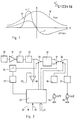
- the variations as a function of X of the excitation function P (X) are represented by the curve 10 illustrated in FIG. 1.
- the variations of the derived function dP / dX are represented by the curve 11 of fig. 1.
- Function f must provide two practical functions: on the one hand, preventing a sudden stop due to mechanical seizure, which guarantees the reliability of the method, and, on the other hand, making it possible to reach the maximum smoothly, which guarantees the precision of the method.
- This condition allows on the one hand an attenuation of the irregularities of the movement and on the other hand a smooth arrival to the maximum of the excitation function.
- this function can be generated by programming a read only memory, but it is necessary that at any time t, the speed v (t) can be assimilated to a local function of the kind: Logic makes it possible to launch the search on an axis, in the right direction by detecting the succession of signs of the derivative dP / dt during an engine command by a periodic signal long of a period when one is at starting point; to stop the search once the relative maximum along this axis has been reached and to switch the entire search circuit to the other axis and so on until the maximum criterion is satisfied.
- the electronic circuit shown in fig. 2 comprises a detector 20 followed by an amplifier 21, a low-pass filter 22 intended to suppress parasites, in particular high frequency disturbances, and a branch block 23 which calculates the derivative dP / dt of the excitation function P.
- a switch 24 controlled by a logic control circuit 25 makes it possible to pass from the "test" phase intended to determine the slope of the derivative to the "control” phase intended to control the speed of movement of one of the components alternately according to the X and Y axes Until the maximum of the excitation function is reached.
- the test circuit consists of a low frequency oscillator 26 which generates a displacement corresponding to a sinisoldal alternation of this component which can be either the optical component or the waveguide, and a rocker 27 which makes it possible to determine and memorize the sign of the test signal at the time of entering the slave state.
- a comparator 28 with threshold 29 makes it possible to determine the zero crossing of the derived signal. This comparator is connected between the branch block 23 and the logic control circuit 25.
- An analog-digital circuit 30 makes it possible to carry out the functional relation linking the speed v to the derivative dP / dt.
- This functional relationship can be programmed by read only memory or obtained by any other appropriate means.
- a switch 31 controlled by the logic control circuit 25 makes it possible to reverse the polarity of the output signal of the circuit 30, as a function of the initial position of the components to be aligned, this polarity being determined during the test.
- Another switch 32 also controlled by the logic control circuit 25 makes it possible to connect the power supply circuits of the motors 35 and 36 alternately to the outputs of the circuit 30, via regulators 37 and 38.
- the motors are of the current type continuous with tachometer and regulators control these motors in speed.
- Two inputs 39, 40 allow respectively to start and stop the process.
- An input 41 makes it possible to fix in advance the number of iterations that one wishes to carry out in order to approach as closely as possible the maximum of the excitation function.
- the mechanical means acting on one of the components in fact comprise the aforementioned motors which act on micrometric displacement members making it possible to perform very precise movements of small amplitude.
Landscapes
- Physics & Mathematics (AREA)
- General Physics & Mathematics (AREA)
- Optics & Photonics (AREA)
- Optical Couplings Of Light Guides (AREA)
- Mechanical Coupling Of Light Guides (AREA)
Priority Applications (1)
| Application Number | Priority Date | Filing Date | Title |
|---|---|---|---|
| AT84810299T ATE39292T1 (de) | 1983-06-24 | 1984-06-21 | Verfahren und vorrichtung zur anpassung einer optischen faser. |
Applications Claiming Priority (2)
| Application Number | Priority Date | Filing Date | Title |
|---|---|---|---|
| CH344583 | 1983-06-24 | ||
| CH3445/83 | 1983-06-24 |
Publications (3)
| Publication Number | Publication Date |
|---|---|
| EP0133416A2 true EP0133416A2 (de) | 1985-02-20 |
| EP0133416A3 EP0133416A3 (en) | 1985-11-21 |
| EP0133416B1 EP0133416B1 (de) | 1988-12-14 |
Family
ID=4256099
Family Applications (1)
| Application Number | Title | Priority Date | Filing Date |
|---|---|---|---|
| EP84810299A Expired EP0133416B1 (de) | 1983-06-24 | 1984-06-21 | Verfahren und Vorrichtung zur Anpassung einer optischen Faser |
Country Status (5)
| Country | Link |
|---|---|
| EP (1) | EP0133416B1 (de) |
| JP (1) | JPS6068305A (de) |
| AT (1) | ATE39292T1 (de) |
| CA (1) | CA1247846A (de) |
| DE (1) | DE3475657D1 (de) |
Families Citing this family (2)
| Publication number | Priority date | Publication date | Assignee | Title |
|---|---|---|---|---|
| JPH0637138B2 (ja) * | 1985-03-30 | 1994-05-18 | マツダ株式会社 | パワ−ユニツトのマウンテイング装置 |
| JPS61226330A (ja) * | 1985-03-30 | 1986-10-08 | Mazda Motor Corp | パワ−ユニツトのマウンテイング装置 |
Family Cites Families (5)
| Publication number | Priority date | Publication date | Assignee | Title |
|---|---|---|---|---|
| CA1066426A (en) * | 1976-11-29 | 1979-11-13 | Frederick D. King | Method and apparatus for alignment of optical fibres with optoelectronic devices |
| JPS606482B2 (ja) * | 1977-06-03 | 1985-02-19 | 日本電気株式会社 | 光フアイバへの光入射自動調整装置 |
| JPS6024921B2 (ja) * | 1978-03-14 | 1985-06-15 | 三菱電機株式会社 | 半導体レ−ザと光伝送路との光軸合せ装置 |
| ATE7965T1 (de) * | 1979-12-03 | 1984-06-15 | The Post Office | Kupplung dielektrischer optischer wellenleiter. |
| JPS5784412A (en) * | 1980-11-14 | 1982-05-26 | Nippon Sheet Glass Co Ltd | Optical axis aligning method of bar-like lens body and optical fiber |
-
1984
- 1984-06-14 CA CA000456609A patent/CA1247846A/fr not_active Expired
- 1984-06-21 AT AT84810299T patent/ATE39292T1/de not_active IP Right Cessation
- 1984-06-21 DE DE8484810299T patent/DE3475657D1/de not_active Expired
- 1984-06-21 EP EP84810299A patent/EP0133416B1/de not_active Expired
- 1984-06-22 JP JP59127729A patent/JPS6068305A/ja active Granted
Also Published As
| Publication number | Publication date |
|---|---|
| EP0133416A3 (en) | 1985-11-21 |
| EP0133416B1 (de) | 1988-12-14 |
| ATE39292T1 (de) | 1988-12-15 |
| CA1247846A (fr) | 1989-01-03 |
| JPS6068305A (ja) | 1985-04-18 |
| JPH0558161B2 (de) | 1993-08-25 |
| DE3475657D1 (en) | 1989-01-19 |
Similar Documents
| Publication | Publication Date | Title |
|---|---|---|
| EP0455530B1 (de) | Faseroptische Messeinrichtung, Gyrometer, Navigations- und Stabilisierungssystem, Stromsensor | |
| EP0605710B1 (de) | System zur interferometrischen Detektion und Lokalisierung von reflektierenden Defekten in Lichtleiterstrukturen | |
| EP0566434B1 (de) | Verfahren zum Justieren einer kontinuierlich abstimmbaren Lichtquelle | |
| FR2662245A1 (fr) | Dispositif de mesure a fibre optique, gyrometre, centrale de stabilisation et capteur de courant ou de champ magnetique. | |
| EP0291394A1 (de) | Bewegungssensor mit zurückgesetzten optischen Fasern | |
| FR2654827A1 (fr) | Dispositif de mesure a fibre optique, gyrometre, centrale de navigation et de stabilisation. | |
| EP0738873A1 (de) | Mehrachsiger faseroptischer Kreisel | |
| EP0027763B1 (de) | Verfahren und Apparat zur Abstandsmessung durch Laserinterferometrie mit zwei Wellenlängen | |
| EP0266249A1 (de) | Dreiachsiges optisches Fiberringinterferometer | |
| EP0133416B1 (de) | Verfahren und Vorrichtung zur Anpassung einer optischen Faser | |
| FR2569841A1 (fr) | Dispositif de mesure opto-electro-mecanique, notamment pour la mesure de valeurs de pression et de force | |
| FR2563623A1 (fr) | Gyroscope a laser a couches minces en boucle ouverte | |
| US4283144A (en) | Method of fiber interferometry zero fringe shift referencing using passive optical couplers | |
| FR2896309A1 (fr) | Dispositif de mesure interferometrique | |
| EP0130944A2 (de) | Verfahren zur Anpassung einer optischen Faser | |
| EP0669525A2 (de) | Interferometrisches System zur Feststellung und Ortung von reflektierenden Fehlern lichtleitender Strukturen | |
| FR2636425A1 (fr) | Dispositif de mesure a fibre optique, gyrometre, centrale de navigation et de stabilisation | |
| FR3083790A1 (fr) | Dispositif de guidage et controle de tension d’un element flexible filiforme tel qu’un cable electrique | |
| FR2612628A1 (fr) | Dispositif de mesure par interferometrie laser | |
| EP0036374A1 (de) | Verfahren und Vorrichtung zum Schweissen mit automatischem Folgen der Schweissnaht | |
| EP0398796B1 (de) | Ringinterferometer | |
| EP0926529B1 (de) | Verfahren und Vorrichtung zur automatischen Positionskorrektur von optischen Elementen in einem optischen Aufbau | |
| EP0048688A2 (de) | Verfahren zur optischen Detektion und/oder zum Messen einer Deformation und/oder einer Versetzung eines Objektes oder eines Objektteiles, Vorrichtung für die Ausführung dieses Verfahrens und Anwendung des Verfahrens | |
| EP0278826B1 (de) | Faseroptische-Vorrichtung zur aus Entfernung Nachweisung des Standes eines physikalischen Parameters gegenüber mindestens einem festgelegten Wert | |
| EP0505233B1 (de) | Einrichtung zum Messen der Winkellage eines schwenkbaren Teils relativ zu einem feststehenden Teil, insbesondere eines Teleskoprahmens relativ zu dessen Halterungsgestell |
Legal Events
| Date | Code | Title | Description |
|---|---|---|---|
| PUAI | Public reference made under article 153(3) epc to a published international application that has entered the european phase |
Free format text: ORIGINAL CODE: 0009012 |
|
| AK | Designated contracting states |
Designated state(s): AT BE CH DE FR GB IT LI LU NL SE |
|
| PUAL | Search report despatched |
Free format text: ORIGINAL CODE: 0009013 |
|
| AK | Designated contracting states |
Designated state(s): AT BE CH DE FR GB IT LI LU NL SE |
|
| 17P | Request for examination filed |
Effective date: 19860502 |
|
| 17Q | First examination report despatched |
Effective date: 19870407 |
|
| GRAA | (expected) grant |
Free format text: ORIGINAL CODE: 0009210 |
|
| AK | Designated contracting states |
Kind code of ref document: B1 Designated state(s): AT BE CH DE FR GB IT LI LU NL SE |
|
| PG25 | Lapsed in a contracting state [announced via postgrant information from national office to epo] |
Ref country code: SE Effective date: 19881214 Ref country code: AT Effective date: 19881214 |
|
| REF | Corresponds to: |
Ref document number: 39292 Country of ref document: AT Date of ref document: 19881215 Kind code of ref document: T |
|
| REF | Corresponds to: |
Ref document number: 3475657 Country of ref document: DE Date of ref document: 19890119 |
|
| ITF | It: translation for a ep patent filed | ||
| GBT | Gb: translation of ep patent filed (gb section 77(6)(a)/1977) | ||
| PG25 | Lapsed in a contracting state [announced via postgrant information from national office to epo] |
Ref country code: LU Free format text: LAPSE BECAUSE OF NON-PAYMENT OF DUE FEES Effective date: 19890630 Ref country code: BE Effective date: 19890630 |
|
| PLBE | No opposition filed within time limit |
Free format text: ORIGINAL CODE: 0009261 |
|
| STAA | Information on the status of an ep patent application or granted ep patent |
Free format text: STATUS: NO OPPOSITION FILED WITHIN TIME LIMIT |
|
| 26N | No opposition filed | ||
| BERE | Be: lapsed |
Owner name: FONDATION SUISSE POUR LA RECHERCHE EN MICROTECHNI Effective date: 19890630 |
|
| ITTA | It: last paid annual fee | ||
| PGFP | Annual fee paid to national office [announced via postgrant information from national office to epo] |
Ref country code: GB Payment date: 19920622 Year of fee payment: 9 |
|
| PGFP | Annual fee paid to national office [announced via postgrant information from national office to epo] |
Ref country code: FR Payment date: 19920626 Year of fee payment: 9 |
|
| PGFP | Annual fee paid to national office [announced via postgrant information from national office to epo] |
Ref country code: DE Payment date: 19920627 Year of fee payment: 9 |
|
| PGFP | Annual fee paid to national office [announced via postgrant information from national office to epo] |
Ref country code: NL Payment date: 19920630 Year of fee payment: 9 |
|
| PGFP | Annual fee paid to national office [announced via postgrant information from national office to epo] |
Ref country code: CH Payment date: 19920811 Year of fee payment: 9 |
|
| PG25 | Lapsed in a contracting state [announced via postgrant information from national office to epo] |
Ref country code: GB Effective date: 19930621 |
|
| PG25 | Lapsed in a contracting state [announced via postgrant information from national office to epo] |
Ref country code: LI Effective date: 19930630 Ref country code: CH Effective date: 19930630 |
|
| PG25 | Lapsed in a contracting state [announced via postgrant information from national office to epo] |
Ref country code: NL Effective date: 19940101 |
|
| GBPC | Gb: european patent ceased through non-payment of renewal fee |
Effective date: 19930621 |
|
| NLV4 | Nl: lapsed or anulled due to non-payment of the annual fee | ||
| PG25 | Lapsed in a contracting state [announced via postgrant information from national office to epo] |
Ref country code: FR Effective date: 19940228 |
|
| REG | Reference to a national code |
Ref country code: CH Ref legal event code: PL |
|
| PG25 | Lapsed in a contracting state [announced via postgrant information from national office to epo] |
Ref country code: DE Effective date: 19940301 |
|
| REG | Reference to a national code |
Ref country code: FR Ref legal event code: ST |