EP0133448B1 - Ausgangsleistungssteuerung einer Kurzschluss-Schweissleistungsquelle - Google Patents
Ausgangsleistungssteuerung einer Kurzschluss-Schweissleistungsquelle Download PDFInfo
- Publication number
- EP0133448B1 EP0133448B1 EP84104601A EP84104601A EP0133448B1 EP 0133448 B1 EP0133448 B1 EP 0133448B1 EP 84104601 A EP84104601 A EP 84104601A EP 84104601 A EP84104601 A EP 84104601A EP 0133448 B1 EP0133448 B1 EP 0133448B1
- Authority
- EP
- European Patent Office
- Prior art keywords
- current
- welding
- short circuit
- voltage
- arc
- Prior art date
- Legal status (The legal status is an assumption and is not a legal conclusion. Google has not performed a legal analysis and makes no representation as to the accuracy of the status listed.)
- Expired
Links
Images


Classifications
-
- B—PERFORMING OPERATIONS; TRANSPORTING
- B23—MACHINE TOOLS; METAL-WORKING NOT OTHERWISE PROVIDED FOR
- B23K—SOLDERING OR UNSOLDERING; WELDING; CLADDING OR PLATING BY SOLDERING OR WELDING; CUTTING BY APPLYING HEAT LOCALLY, e.g. FLAME CUTTING; WORKING BY LASER BEAM
- B23K9/00—Arc welding or cutting
- B23K9/12—Automatic feeding or moving of electrodes or work for spot or seam welding or cutting
- B23K9/124—Circuits or methods for feeding welding wire
- B23K9/125—Feeding of electrodes
-
- B—PERFORMING OPERATIONS; TRANSPORTING
- B23—MACHINE TOOLS; METAL-WORKING NOT OTHERWISE PROVIDED FOR
- B23K—SOLDERING OR UNSOLDERING; WELDING; CLADDING OR PLATING BY SOLDERING OR WELDING; CUTTING BY APPLYING HEAT LOCALLY, e.g. FLAME CUTTING; WORKING BY LASER BEAM
- B23K9/00—Arc welding or cutting
- B23K9/09—Arrangements or circuits for arc welding with pulsed current or voltage
- B23K9/091—Arrangements or circuits for arc welding with pulsed current or voltage characterised by the circuits
Definitions
- This invention relates to a method according to the preamble of claim 1.
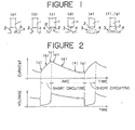
- FIG. 1 Shown in Figure 1 are sequential stages through which a molten drop is formed and transferred in one cycle of a consumable electrode welding process with alternate short circuiting and arcing phases.
- a consumable electrode hereinafter referred to simply as "welding wire” for brevity
- welding wire a consumable electrode
- FIG. 1 shown at (a) is an initial stage of short circuiting in which the molten drop 2 begins to contact the weld pool 4, at (b) a middle stage of the short circuiting in which the molten drop 2 is in full contact with and being transferred to the weld pool 4, at (c) a final stage of the short circuiting in which necking occurs between the welding wire 1 and molten pool 4 as a result of transfer of the molten drop 2 to the weld pool 4, at (d) an instant of restricting an arc 3, at (e) an initial arcing stage in which the tip end of the welding wire 1 is melted, forming a growing molten drop 2 thereat, and at (f) and (g) arcing stages immediately before short circuiting by the molten drop 2 which is about to contact the weld pool 4.
- the stages (a) to (g) are repeated in the welding operation.
- FIG. 2 there are shown waveforms of welding current and voltage of a conventional welding power source which has constant potential characteristics by combined use of a reactor.
- the reference characters (a) to (g) which indicate particular points of the waveforms in Figure 2 correspond to the molten drop forming and transferring stages (a) to (g) of Figure 1, respectively.
- the welding current begins to increase with a certain time constant immediately after short circuiting between the molten drop 2 and weld pool 4, and, if the sectional area of a contact portion A of the molten drop and weld pool 4 is small, that is to say, if the welding current becomes larger before the transfer to the weld pool 4 of the molten drop 2, the short circuit is ruptured and an arc is generated, causing spattering.
- necking occurs to the molten drop 2 and the short circuit is ruptured to generate an arc again.
- the welding current reaches a highest value at this re-arcing time, and a large amount of spatters is produced by repulsive energy of the arc which shakes the weld pool 4.
- the welding current increases when the preceding short circuit period is long and decreases when preceded by a short circuit period. Accordingly, the size of the molten drop 2 which is formed in the stages (d), (e) and (f) becomes irregular, and, if it is too small, an unfused portion of the welding wire 1 is stuck into the weld pool 4 in the stage (g), putting the welding operation in a considerably instable state.
- the welding current should be small in the stage (g) in order to urge the molten drop 2 toward the weld pool to encourage the short circuiting.
- a welding power source has constant potential characteristics, reductions in arc length are reflected by current increases. Consequently, the short circuiting becomes more difficult and the molten drop grows into a large size, resulting not only in irregular short circuit periods but also in spattering of larger droplets.
- the voltage increase dV/dt during the short circuit time is not only dependent on the necking but also on the extension length of the consumable electrode projecting from the terminal and on the duration of the short circuit.
- the projecting consumable electrode is heated which causes an increase in its resistance.
- the increase in resistance causes an increase in voltage and the longer the projecting consumable electrode is, the greater is the increase in voltage.
- the longer the short circuit time or the time till the generation of the necking is the greater is the increase in voltage.
- an alteration of the extension length of the projecting consumable electrode cannot be avoided.
- the short circuit time changes within a broad range between 2 and 5 ms or more.
- the invention is based on the object to develop a method according to the preamble of claim 1 in such a way that the spatter is greatly reduced in a reliable way.
- the minimum voltage V L is stored during the short circuit time and, furthermore, a voltage V N dependent on the duration of the short circuit and the length of the projecting consumable electrode is generated by means of an integrating means. Moreover, a voltage V exclusively due to the necking is generated in that the minimum voltage V L and the voltage V N obtained by integration are subtracted from the measured voltage V M . Thus, the effect on the alteration of the voltage between the terminal of the consumable electrodes and the workpiece resulting from alternations of the length of the projecting consumable electrode is completely eliminated and a change in voltage resulting alone from the necking is detected. Due to this, the reduction of the current of a relatively high current value can be determined very accurately and a spatter can be greatly reduced.
- the short circuit is terminated at the occurrence of the necking so that the molten metal is ruptured by surface tension and gravity. After this the current is increased in the following arcing period, in order to form a next molten drop of desired size.
- the present invention concerns the control of output of a power source in consumable electrode arc welding wherein a welding wire is fed toward a workpiece through a contact tube while blowing a shielding gas from the nozzle thereby to wrap in an arc which is generated across a gap between the welding wire and workpiece, repeating an arcing phase alternately with a short circuiting phase.
- FIG. 3 there are shown output waveforms of current and voltage which have been found to be optimum as a result of an extensive study on the welding current in consumable electrode arc welding processes involving alternate short circuit and arcing phases.
- the reference characters (a) to (g) which indicate particular points on the current and voltage waves correspond to the drop forming and transferring stages (a) to (g) of Fig. 1, respectively.
- the welding current should be at a low level I D for keeping the contact portion A of a molten drop 2 and weld pool 4 from pinching force of the welding current which is hindrous to strong contact between the molten drop 2 and weld pool 4.
- the current is retained at the low level I D for a time period To of 1-4 msec, optimally 1.5-2.5 msec.
- the current is desired to be as low as possible, generally lower than 100A. It has also been confirmed that, with a low feed rate of the welding wire 1, the current l o should be lower than that.
- a high current I s p with suitable Joule energy and pinching force is applied to accelerate the transfer of the molten drop 2 to the weld pool 4.
- This peak current is applied for the purpose of urging the transfer of the molten drop 2 before an unfused portion of the welding wire is stuck into the weld pool 4, and urging necking of the molten metal after the transfer. Unless the peak current I s p is applied, welding condition becomes extremely instable.
- the peak current I s p is applied for a time period extending up to the stage (c) where necking occurs to the molten drop 2, which time period normally varies in the range of 1-5 msec and is difficult to preset at a particular value.
- necking of the molten metal can be detected from a voltage variation over a certain time period (a differentiated value dV/dt) across the welding wire and workpiece, or by various methods which will be described hereinlater.
- the welding current is rapidly decreased to a low level I RA , and in the following stage (d) an arc is generated across the gap.
- the rapid lowering of the welding current in the stage (c) is effected for the purpose of preventing the molten drop 2 from being partly spattered by arcing upon rupture of the neck portion of the molten drop 2 and weakening the arc pressure which is applied to the weld pool at the instant of arc generation. If the arc pressure is strong, the weld pool 4 is pushed toward the outer periphery of a bead, impairing uniformity in the appearance of the bead and in some cases part of the weld pool is spattered.
- the low level current I RA is varied depending upon the wire feed rate but desired to be in the range of 20-200A. If the current I RA is lower than 20A, it will increase probabilities of arc extinction at the time of re-arcing, and, if higher than 200A, it will increase the amount of spatter. Ideally, the current I RA should be at the lowest level which will not cause arc extinction and its lower limit is not restricted to 20A.
- the welding current is raised to a peak arc current I AP in the stage (d), retaining that level for a predetermined time period extending to the stage (e).
- the peak current retention time T AP from the stages (d) to (e) is a duration in which a molten drop is formed at the tip end of the welding wire for transfer to the weld pool at the next short circuiting.
- the peak current retention time T A p and the value of peak arc current I AP are detemined such that the molten drop will grow into a desired size during this time period.
- the current I AP in the time T AP should be at a high level which is sufficient for preventing occurrence of short circuiting.
- the peak arc current l AP which is sufficient for preventing short circuiting during the peak current retention time T A p varies depending upon the welding wire feed rate. For example, it is about 260A when the wire feed speed is 5.2 m/min (mean welding current: 180A), and about 340A when the wire feed speed is 8.4 m/min (mean welding current: 240A).
- the peak arc current I AP must be higher than the value of mean welding current.
- the current increase to a sufficiently high level is useful for preventing short circuiting during the peak current retention time T A p as mentioned above, it is also effective to resort to constant potential characteristics which tend to repress short circuiting by increasing current in response to reductions in arc length. In this case, the current increase will augment the force of arc as well as the burn-up rate of the welding wire to broaden the gap between the molten drop and weld pool.
- the welding current is retained at a low level I AB in order to short-circuit the molten drop into the weld pool as soon as possible.
- the current is increased by reductions in arc length and therefore the force of arc is increased on approach of short circuiting, depressing the weld pool by the increased arc force in a manner to maintain a gap between the molten drop and weld pool, thus creating a state which discourages short circuiting.
- the level of current I AB is too high, the short circuiting is delayed and the molten drop grows into an unnecessarily large size, resulting in irregular short circuit periods and spattering of large molten drops.
- the low arcing current I AB is maintained until the stage (g) at which the short circuiting occurs.
- Welding method 10 minutes bead-on-plate welding with a welding torch supported on a carriage.
- the performance quality was evaluated according to the amount of spattering as measured by way of the weight of spatter deposition on the nozzle during a period of 10 minutes, arc stability as observed from the welding current waveforms on an oscilloscope, and bead appearance.
- the results of evaluation are shown in Table 2 together with the results of evaluation of the conventional examples 1 ho 3.
- FIGs 4 and 5 there are shown waveforms of welding current and voltage in Example 2 as observed by an oscilloscope.
- the waveforms are shown on a time axis of a smaller scale than in Figure 4.
- Figures 6 and 7 show the waveforms of welding current and voltage in Conventional Example 2 as observed on an oscilloscope, using in Figure 7 a time axis of a smaller scale than in Figure 6.
- the amount of spatter is reduced to 1/5 to 1/6 of the amounts marked by the conventional method.
- the welding current in the method of the present invention is regular in period and peak value of the welding current. This means that short circuiting and arcing are repeated regularly with stability in arc force, arc length, molten drop diameter, short circuiting behavior, weld pool condition etc. Namely, according to the method of the present invention, it becomes possible to reduce the amount of spatter and obtain uniform and clean bead apparance, improving the performance quality of welding operation to unnecessitate any post treatment.
- the waveform of welding current in the conventional method is irregular in period and peak value as seen in Figure 6. It follows that short circuiting and arcing occur in a random fashion, with fluctuating variations in arc force, arc length and molten drop diameter.
- the operation according to the conventional method suffers from instability of the arc, disturbances of the weld pool and a large amount of spatter, and the performance quality is impaired by the sporadically varying arc force which sometimes reaches an extraordinary high level, splashing the weld pool and deteriorating the bead appearance by forming a whisker-like projection at the bead edge.
- Fig. 8 and 9 show an output control system which can serve for this purpose.
- Fig. 8 a system for controlling the output of a welding power source, including a welding voltage detector 5 which detects the welding voltage and is connected to input terminals of a short circuit detector 6 and an arc extinction detector 7.
- the output terminal of short circuit detector 6 is connected to a first input terminal of an OR circuit 8, a first inverted input terminal of an AND circuit 9, and a first input terminal of an AND circuit 10.
- the output terminal of arc extinction detector 7 is connected to a second input terminal of OR circuit 8 and a second inverted input terminal of AND circuit 9.
- OR circuit 8 is connected to an input terminal of a switch drive circuit 12 which opens and closes a switch 11, while the output terminal of AND circuit 9 is connected to an input terminal of a switch drive circuit 14 which opens and closes a switch 13.
- the switches 11 and 13 are connected in series between power sources which supply a positive voltage +V and a negative voltage -V, respectively.
- a node P1 between the switches 11 and 13 is connected to a first input terminal of an operational amplifier 16 through a resistor 15, and a capacitor 17 is connected between the first input terminal and an output terminal P2 of the operational amplifier 16.
- the second input terminal of the operational amplifier 16 is grounded. Further, output terminal P2 of the operational amplifier 16 is connected to a first input terminal of a comparator 18.
- the second input terminal of the comparator 18 is grounded, and its output terminal P3 is connected to the second input terminal of AND circuit 10.
- the output terminal of AND circuit 10 is connected to an input terminal of a second stage current l s p setting circuit 19, the output terminal of which is connected to an input terminal of a welding power source 20.
- a timer is constituted by the section which is enclosed by a chain, including the above-mentioned switches 11 and 13, resistor 15, capacitor 17, operational amplifier 16 and comparator 18.
- a short circuit is detected by the short circuit detector 6 which receives from the welding voltage detector 5 signals indicative of welding voltage levels.
- the detector 6 produces an output signal of "high” level, so that OR and AND circuits 8 and 9 produce output signals of "high” and “low” levels, respectively.
- switch 11 is closed by operation of switch drive circuit 12, and switch 13 is opened by operation of switch drive circuit 14. Accordingly, the voltage at the output terminal P2 of the operational amplifier 16 is reduced according to a time constant as determined by resistor 15 and capacitor 17. If the voltage of the output terminal P2 drops to OV or lower, the comparator 18 produces a signal of "high" level at its output terminal P3.
- the signal at the terminal P3 is fed to the second stage current I s p setting circuit 19 through AND circuit 10, and the circuit 19 produces a signal which turns the output of the welding power source 20 to the second stage current I s p of high level.
- the second stage current I s p is fed to the welding wire 1.
- the output signals of the short circuit detector 6 and arc extinction detector 7 are both at "low” level, so that the output signals of OR and AND circuits 8 and 9 are at "low” and “high” levels respectively.
- the switch 11 is therefore opened by operation of the switch drive circuit 12, while the switch 13 is closed by operation of the switch drive circuit 14. Accordingly, the output terminal P2 of the operational amplifier 16 retains a positive voltage, and the output terminal P3 of the comparator J turns to "low” level.
- the output signal of AND circuit 10 is at "low” level, so that a signal commanding output of short circuit current is not fed to the welding power source 20 from the second stage current l s p setting circuit 19.
- the short circuit current setting circuit 19 is actuated to supply the welding power source 20 with a signal commanding output of the second stage peak current l s p. In response to this signal, the welding power source 20 feeds the second stage current to the welding wire.
- the short circuit detector 6 is actuated to produce a signal of "high” level at its output terminal, and the output of AND circuit 10 turns to "high” level, actuating the second stage current I s p setting circuit 19 to supply the welding power source 20 with a signal commanding output of the second stage peak current I SP .
- the welding power source 20 feeds the second stage peak current I s p of high level.
- the second stage peak current I s p of high level is supplied as soon as a welding wire is short-circuited to a workpiece, and a molten drop is formed at the distal end of the welding wire in short time period, starting an arc upon rupture of the molten metal bridge.
- one arc extinction detector 7 is composed of a comparator which has a predetermined comparative level signal and outputs the signal of "high" level receiving the no load voltage signal from the welding voltage detector 5.
- the welding voltage is 20-45 Volt in arc generation, whereas no load voltage is about 65 Volt in arc extinction, so that the detector can detect the arc exctinction by predetermining a comparative level between the welding voltage and no load voltage.
- Another arc extinction detector 7 is composed of a comparator which outputs the signal of "high" level in absence of the current signal from a welding current detector 4 (as shown by broken line in Fig. 8).
- the short circuit current shows a quick rise toward the second stage current level immediately after short circuiting without the first stage at the time of arc start and after a predetermined time of the first stage in an ordinary state of welding operation, in contrast to the low rising rate of short circuit current which is supplied from the conventional power supply.
- V N is the voltage increment due to the increase in resistance of a wire extension upon elapse of time t from the second stage, as expressed by the following equation.
- V(t) is the welding voltage in the second stage
- k is the constant according to welding wire diameter and material.
- the integration starts to calculate V N when the second stage starts.
- the minimum welding voltage V L is stored in a memory after the welding current reaches the second stage level I SP as shown in Fig. 10. Then, a voltage increment for a period of c is calculated with regard to a particular function V(t). After this, the welding voltage V M is being measured continuously, and the welding current is lowered at a time t 1 when reaches a predetermined value, which corresponds to the time point when necking occurs.
- the welding wire diameter is 1.2 mm and the peak current I s p is 400A, AV is 0.3-0.6 V and the voltage V N after 1 millisecond is 0.20-0.25 V.
- FIG. 11 Shown in Fig. 11 is an example of the control system which is-constructed to this effect, wherein an integrating circuit 111 receives at one terminal 111 a the outpout of a voltage detector 112 which detects the voltage across a welding torch 104 and a workpiece 106, and at the other terminal 111 b a signal supplied from a welding current detector 113 which indicates the current flowing through a welding wire 103, to integrate the welding voltage from a time point when the welding current through the wire 103 reaches the second stage peak current I SP , for example, from point b of Fig. 10.
- a minimum voltage memory 114 stores the lowest value of voltage after the welding current reaches the second stage peak current I SP in short circuit condition.
- Indicated at 115 is a subtractor which receives a signal of the welding voltage V M from the voltage detector 112, a signal of the integrated voltage V N from the integrating circuit 111 and a signal of the lowest voltage V L from the minimum voltage memory 114, to calculate The results of calculation AV is fed to one input terminal of a comparator 116, which receives at the other input terminal a signal of a preset value Ev from a necking voltage control 117.
Landscapes
- Engineering & Computer Science (AREA)
- Physics & Mathematics (AREA)
- Plasma & Fusion (AREA)
- Mechanical Engineering (AREA)
- Arc Welding Control (AREA)
Claims (2)

Applications Claiming Priority (12)
| Application Number | Priority Date | Filing Date | Title |
|---|---|---|---|
| JP147632/83 | 1983-08-11 | ||
| JP58147632A JPS6040676A (ja) | 1983-08-11 | 1983-08-11 | 短絡を伴なう溶接電源の出力制御方法 |
| JP147633/83 | 1983-08-11 | ||
| JP58147633A JPS6040677A (ja) | 1983-08-11 | 1983-08-11 | 短絡を伴なう溶接電源の出力制御方法 |
| JP58212872A JPS60106673A (ja) | 1983-11-12 | 1983-11-12 | 溶接電源の出力制御方法 |
| JP212873/83 | 1983-11-12 | ||
| JP21287383A JPS60106674A (ja) | 1983-11-12 | 1983-11-12 | 溶接電源の出力制御方法 |
| JP212872/83 | 1983-11-12 | ||
| JP21728883A JPS60108179A (ja) | 1983-11-17 | 1983-11-17 | 消耗電極式ア−ク溶接方法 |
| JP217288/83 | 1983-11-17 | ||
| JP112884A JPS60145277A (ja) | 1984-01-06 | 1984-01-06 | 溶接電源の出力制御方法 |
| JP1128/84 | 1984-01-06 |
Publications (2)
| Publication Number | Publication Date |
|---|---|
| EP0133448A1 EP0133448A1 (de) | 1985-02-27 |
| EP0133448B1 true EP0133448B1 (de) | 1989-08-09 |
Family
ID=27547584
Family Applications (1)
| Application Number | Title | Priority Date | Filing Date |
|---|---|---|---|
| EP84104601A Expired EP0133448B1 (de) | 1983-08-11 | 1984-04-24 | Ausgangsleistungssteuerung einer Kurzschluss-Schweissleistungsquelle |
Country Status (3)
| Country | Link |
|---|---|
| US (1) | US4546234A (de) |
| EP (1) | EP0133448B1 (de) |
| DE (1) | DE3479303D1 (de) |
Cited By (1)
| Publication number | Priority date | Publication date | Assignee | Title |
|---|---|---|---|---|
| US10500667B2 (en) | 2009-04-08 | 2019-12-10 | Panasonic Intellectual Property Management Co., Ltd. | Arc welding method and arc welding apparatus for adjusting a welding current waveform responsive to a setting voltage adjustment |
Families Citing this family (90)
| Publication number | Priority date | Publication date | Assignee | Title |
|---|---|---|---|---|
| US4954691A (en) * | 1986-12-10 | 1990-09-04 | The Lincoln Electric Company | Method and device for controlling a short circuiting type welding system |
| US4866247A (en) * | 1986-12-11 | 1989-09-12 | The Lincoln Electric Company | Apparatus and method of short circuiting arc welding |
| US4717807A (en) * | 1986-12-11 | 1988-01-05 | The Lincoln Electric Company | Method and device for controlling a short circuiting type welding system |
| US4897523A (en) * | 1986-12-11 | 1990-01-30 | The Lincoln Electric Company | Apparatus and method of short circuiting arc welding |
| US5001326A (en) * | 1986-12-11 | 1991-03-19 | The Lincoln Electric Company | Apparatus and method of controlling a welding cycle |
| US5148001A (en) * | 1986-12-11 | 1992-09-15 | The Lincoln Electric Company | System and method of short circuiting arc welding |
| US4835360A (en) * | 1986-12-11 | 1989-05-30 | The Lincoln Electric Company | Method and device for controlling a short circuiting type welding system |
| US5003154A (en) * | 1986-12-11 | 1991-03-26 | The Lincoln Electric Company | Apparatus and method of short circuiting arc welding |
| AU596761B2 (en) * | 1987-12-21 | 1990-05-10 | Lincoln Electric Company, The | Apparatus and method of short circuiting arc welding |
| US5495091A (en) * | 1989-02-27 | 1996-02-27 | Mitsubishi Denki Kabushiki Kaisha | Pulse welding apparatus |
| GB2268009B (en) * | 1989-02-27 | 1994-09-14 | Mitsubishi Electric Corp | Pulse welding apparatus |
| GB2269495B (en) * | 1989-02-27 | 1994-09-28 | Mitsubishi Electric Corp | Pulse welding apparatus |
| WO1990009856A1 (fr) * | 1989-02-28 | 1990-09-07 | Mitsubishi Denki Kabushiki Kaisha | Appareil de soudage par impulsions |
| US6087626A (en) * | 1998-02-17 | 2000-07-11 | Illinois Tool Works Inc. | Method and apparatus for welding |
| JP3484457B2 (ja) * | 1999-04-23 | 2004-01-06 | ミヤチテクノス株式会社 | 抵抗溶接電源装置 |
| AUPQ528400A0 (en) | 2000-01-27 | 2000-02-17 | Crc For Welded Structures Limited | A welding control system |
| US6501049B2 (en) | 2001-01-23 | 2002-12-31 | Lincoln Global, Inc. | Short circuit arc welder and method of controlling same |
| DE10120744A1 (de) * | 2001-04-20 | 2002-10-24 | Univ Berlin Tech | Verfahren zur Minimierung des Energieeintrags beim Wiederzünden im MSG-Schweißprozess |
| US6794608B2 (en) | 2001-10-30 | 2004-09-21 | Tri Tool Inc. | Welding current control system and method |
| AUPS274002A0 (en) * | 2002-06-03 | 2002-06-20 | University Of Wollongong, The | Control method and system for metal arc welding |
| US6969823B2 (en) * | 2002-07-23 | 2005-11-29 | Illinois Tool Works Inc. | Method and apparatus for controlling a welding system |
| JP4739641B2 (ja) * | 2002-09-26 | 2011-08-03 | 株式会社ダイヘン | 短絡アーク溶接用電源装置及びロボット溶接装置 |
| US7265320B2 (en) * | 2003-09-26 | 2007-09-04 | Tsinghua University | Method and system for reducing spatter in short-circuit transfer gas shielded arc welding |
| US7109439B2 (en) * | 2004-02-23 | 2006-09-19 | Lincoln Global, Inc. | Short circuit arc welder and method of controlling same |
| US20070221643A1 (en) * | 2004-04-29 | 2007-09-27 | Lincoln Global, Inc. | Gas-less process and system for girth welding in high strength applications including liquefied natural gas storage tanks |
| JP3941802B2 (ja) * | 2004-07-08 | 2007-07-04 | 松下電器産業株式会社 | アーク溶接制御方法及びアーク溶接装置 |
| US8785816B2 (en) | 2004-07-13 | 2014-07-22 | Lincoln Global, Inc. | Three stage power source for electric arc welding |
| US8269141B2 (en) | 2004-07-13 | 2012-09-18 | Lincoln Global, Inc. | Power source for electric arc welding |
| US8581147B2 (en) | 2005-03-24 | 2013-11-12 | Lincoln Global, Inc. | Three stage power source for electric ARC welding |
| US9956639B2 (en) | 2005-02-07 | 2018-05-01 | Lincoln Global, Inc | Modular power source for electric ARC welding and output chopper |
| US9855620B2 (en) | 2005-02-07 | 2018-01-02 | Lincoln Global, Inc. | Welding system and method of welding |
| JP4875311B2 (ja) * | 2005-03-11 | 2012-02-15 | 株式会社ダイヘン | 消耗電極アーク溶接のくびれ検出時電流制御方法 |
| US7495193B2 (en) * | 2005-03-15 | 2009-02-24 | Lincoln Global, Inc. | Pipe seam tack welding methods and apparatus using modified series arc welding |
| US9647555B2 (en) | 2005-04-08 | 2017-05-09 | Lincoln Global, Inc. | Chopper output stage for arc welder power source |
| JP4809014B2 (ja) * | 2005-07-29 | 2011-11-02 | 株式会社ダイヘン | ロボット溶接のアークスタート制御方法 |
| FI119923B (fi) * | 2005-09-08 | 2009-05-15 | Kemppi Oy | Menetelmä ja laitteisto lyhytkaarihitsausta varten |
| CA2622134C (en) * | 2005-09-12 | 2013-12-24 | Esab Ab | Control method for mig/mag-welding and welding equipment applying this method |
| US8704131B2 (en) * | 2006-03-31 | 2014-04-22 | Illinois Tool Works Inc. | Method and apparatus for pulse welding |
| US9085041B2 (en) | 2009-01-13 | 2015-07-21 | Lincoln Global, Inc. | Method and system to start and use combination filler wire feed and high intensity energy source for welding |
| US10086461B2 (en) * | 2009-01-13 | 2018-10-02 | Lincoln Global, Inc. | Method and system to start and use combination filler wire feed and high intensity energy source for welding |
| JP4807474B2 (ja) * | 2009-06-19 | 2011-11-02 | パナソニック株式会社 | 消耗電極式アーク溶接方法および消耗電極式アーク溶接装置 |
| AT508146B1 (de) * | 2009-08-10 | 2010-11-15 | Fronius Int Gmbh | Verfahren zum auftrennen eines kurzschlusses beim kurzlichtbogenschweissen und schweissgerät zum kurzlichtbogenschweissen |
| JP5170321B2 (ja) * | 2009-11-25 | 2013-03-27 | パナソニック株式会社 | 溶接方法および溶接装置 |
| US10239146B2 (en) | 2010-02-12 | 2019-03-26 | Illinois Tool Works Inc. | Method and apparatus for welding with short clearing prediction |
| EP2580017B1 (de) * | 2010-06-14 | 2014-04-16 | Esab AB | Verfahren zur automatischen einstellung eines schweissparameters für mig/mag-schweissen und steuerung zur durchführung des verfahrens |
| CN102380691B (zh) * | 2010-08-31 | 2014-11-05 | 株式会社大亨 | 消耗电极电弧焊接的缩颈检测控制方法 |
| JP5801058B2 (ja) * | 2011-02-07 | 2015-10-28 | 株式会社ダイヘン | 溶接装置および炭酸ガスアーク溶接方法 |
| US10065257B2 (en) | 2011-06-23 | 2018-09-04 | Lincoln Global, Inc. | Welding system with controlled wire feed speed during arc initiation |
| US9095921B2 (en) * | 2011-10-14 | 2015-08-04 | Lincoln Global, Inc. | Real time inductance monitoring in welding and cutting power supply |
| US10118243B2 (en) | 2011-10-14 | 2018-11-06 | Lincoln Global, Inc. | Real time inductance monitoring in welding and cutting power supply |
| US10040143B2 (en) | 2012-12-12 | 2018-08-07 | Illinois Tool Works Inc. | Dabbing pulsed welding system and method |
| US10906114B2 (en) | 2012-12-21 | 2021-02-02 | Illinois Tool Works Inc. | System for arc welding with enhanced metal deposition |
| US9950383B2 (en) | 2013-02-05 | 2018-04-24 | Illinois Tool Works Inc. | Welding wire preheating system and method |
| US10835983B2 (en) | 2013-03-14 | 2020-11-17 | Illinois Tool Works Inc. | Electrode negative pulse welding system and method |
| US9808879B2 (en) | 2013-04-12 | 2017-11-07 | Isawe, Llc | Welding diagnostic device for identifying metal transfer modes during a welding process and a method of identifying metal transfer modes of a welding process |
| US11045891B2 (en) | 2013-06-13 | 2021-06-29 | Illinois Tool Works Inc. | Systems and methods for anomalous cathode event control |
| US10828728B2 (en) | 2013-09-26 | 2020-11-10 | Illinois Tool Works Inc. | Hotwire deposition material processing system and method |
| US10464168B2 (en) | 2014-01-24 | 2019-11-05 | Lincoln Global, Inc. | Method and system for additive manufacturing using high energy source and hot-wire |
| EP3020498B1 (de) | 2014-02-14 | 2018-05-09 | Panasonic Intellectual Property Management Co., Ltd. | Lichtbogenschweissverfahren |
| US10406622B2 (en) * | 2014-02-18 | 2019-09-10 | Daihen Corporation | Arc-welding power supply |
| US11154946B2 (en) | 2014-06-30 | 2021-10-26 | Illinois Tool Works Inc. | Systems and methods for the control of welding parameters |
| US11198189B2 (en) | 2014-09-17 | 2021-12-14 | Illinois Tool Works Inc. | Electrode negative pulse welding system and method |
| US11478870B2 (en) | 2014-11-26 | 2022-10-25 | Illinois Tool Works Inc. | Dabbing pulsed welding system and method |
| US10189106B2 (en) | 2014-12-11 | 2019-01-29 | Illinois Tool Works Inc. | Reduced energy welding system and method |
| US11370050B2 (en) | 2015-03-31 | 2022-06-28 | Illinois Tool Works Inc. | Controlled short circuit welding system and method |
| US11285559B2 (en) * | 2015-11-30 | 2022-03-29 | Illinois Tool Works Inc. | Welding system and method for shielded welding wires |
| US10610946B2 (en) | 2015-12-07 | 2020-04-07 | Illinois Tool Works, Inc. | Systems and methods for automated root pass welding |
| US12194579B2 (en) | 2015-12-10 | 2025-01-14 | Illinois Tool Works Inc. | Systems, methods, and apparatus to preheat welding wire |
| US10675699B2 (en) | 2015-12-10 | 2020-06-09 | Illinois Tool Works Inc. | Systems, methods, and apparatus to preheat welding wire |
| US10695856B2 (en) | 2016-10-07 | 2020-06-30 | Illinois Tool Works Inc. | System and method for short arc welding |
| US10766092B2 (en) | 2017-04-18 | 2020-09-08 | Illinois Tool Works Inc. | Systems, methods, and apparatus to provide preheat voltage feedback loss protection |
| US10870164B2 (en) | 2017-05-16 | 2020-12-22 | Illinois Tool Works Inc. | Systems, methods, and apparatus to preheat welding wire |
| EP3634684B1 (de) | 2017-06-09 | 2022-10-05 | Illinois Tool Works Inc. | Schweissbrenner mit erster kontaktspitze zum vorwärmen von schweissdraht und einer zweiten kontaktspitze |
| US11590598B2 (en) | 2017-06-09 | 2023-02-28 | Illinois Tool Works Inc. | Systems, methods, and apparatus to preheat welding wire |
| CN111315524A (zh) | 2017-06-09 | 2020-06-19 | 伊利诺斯工具制品有限公司 | 具有两个触头和用于将电流传导至触头的多个液冷组件的焊接炬 |
| CN111386168A (zh) | 2017-06-09 | 2020-07-07 | 伊利诺斯工具制品有限公司 | 具有两个接触焊嘴和用于冷却并传导电流的制冷主体的用于焊接炬的焊接组装件 |
| US11524354B2 (en) | 2017-06-09 | 2022-12-13 | Illinois Tool Works Inc. | Systems, methods, and apparatus to control weld current in a preheating system |
| CN107214402A (zh) * | 2017-06-21 | 2017-09-29 | 成都华远电器设备有限公司 | 一种短路过渡的熔滴控制电路及方法 |
| US11020813B2 (en) | 2017-09-13 | 2021-06-01 | Illinois Tool Works Inc. | Systems, methods, and apparatus to reduce cast in a welding wire |
| US11027362B2 (en) | 2017-12-19 | 2021-06-08 | Lincoln Global, Inc. | Systems and methods providing location feedback for additive manufacturing |
| CN113165097B (zh) | 2018-08-31 | 2023-11-03 | 伊利诺斯工具制品有限公司 | 用于电阻式地预加热电极丝的埋弧焊系统和埋弧焊焊炬 |
| US11014185B2 (en) | 2018-09-27 | 2021-05-25 | Illinois Tool Works Inc. | Systems, methods, and apparatus for control of wire preheating in welding-type systems |
| EP3898055A2 (de) | 2018-12-19 | 2021-10-27 | Illinois Tool Works, Inc. | Kontaktspitze, drahtvorwärmanordnung, kontaktspitzenanordnung und mit einer abschmelzenden elektrode gespeistes schweisssystem |
| US20200238418A1 (en) * | 2019-01-24 | 2020-07-30 | Illinois Tool Works Inc. | Systems and methods with integrated switch for controlled short circuit welding processes |
| US11623292B2 (en) | 2019-03-29 | 2023-04-11 | Lincoln Global, Inc. | Real time resistance monitoring of an arc welding circuit |
| US12583048B2 (en) | 2019-03-29 | 2026-03-24 | Illinois Tool Works Inc. | Methods and apparatus to convert welding-type power to welding-type power and resistive preheating power |
| US12103121B2 (en) | 2019-04-30 | 2024-10-01 | Illinois Tool Works Inc. | Methods and apparatus to control welding power and preheating power |
| US11772182B2 (en) | 2019-12-20 | 2023-10-03 | Illinois Tool Works Inc. | Systems and methods for gas control during welding wire pretreatments |
| RU2736144C1 (ru) * | 2020-01-10 | 2020-11-11 | Сергей Валентинович Федюкин | Способ дуговой сварки плавящимся электродом в среде защитных газов |
| US20210237189A1 (en) * | 2020-01-30 | 2021-08-05 | Illinois Tool Works Inc. | Systems and methods to control welding processes using a voltage-controlled control loop |
Family Cites Families (9)
| Publication number | Priority date | Publication date | Assignee | Title |
|---|---|---|---|---|
| GB1112511A (en) * | 1965-03-11 | 1968-05-08 | Lincoln Electric Company Ltd | Improvements in or relating to electric arc welding apparatus |
| DE1806648A1 (de) * | 1968-11-02 | 1970-05-21 | Erdmann Jesnitzer Dr Ing Habil | Vorrichtung und Verfahren zur Kontrolle von Elektroschweissverfahren |
| GB1399101A (en) * | 1971-08-24 | 1975-06-25 | Welding Inst | Arc welding apparatus |
| NL7216070A (de) * | 1971-11-30 | 1973-06-04 | ||
| US3809853A (en) * | 1972-08-24 | 1974-05-07 | Union Carbide Corp | Method for short circuit metal transfer arc welding |
| SE425060B (sv) * | 1978-05-30 | 1982-08-30 | Thermal Dynamics Corp | Anordning for kortbagsvetsning |
| SE416625B (sv) * | 1979-03-01 | 1981-01-26 | Thermal Dynamics Corp | Anordning for spraybagsvetsning |
| JPS57142769A (en) * | 1981-02-27 | 1982-09-03 | Mitsubishi Electric Corp | Electric power source for consumable electrode type arc welding |
| DE3213278A1 (de) * | 1981-04-10 | 1982-11-18 | Mitsubishi Denki K.K., Tokyo | Mit kurzschluss arbeitende lichtbogen-uebertragschweissmaschine |
-
1984
- 1984-04-04 US US06/596,686 patent/US4546234A/en not_active Ceased
- 1984-04-24 EP EP84104601A patent/EP0133448B1/de not_active Expired
- 1984-04-24 DE DE8484104601T patent/DE3479303D1/de not_active Expired
Cited By (1)
| Publication number | Priority date | Publication date | Assignee | Title |
|---|---|---|---|---|
| US10500667B2 (en) | 2009-04-08 | 2019-12-10 | Panasonic Intellectual Property Management Co., Ltd. | Arc welding method and arc welding apparatus for adjusting a welding current waveform responsive to a setting voltage adjustment |
Also Published As
| Publication number | Publication date |
|---|---|
| US4546234A (en) | 1985-10-08 |
| DE3479303D1 (en) | 1989-09-14 |
| EP0133448A1 (de) | 1985-02-27 |
Similar Documents
| Publication | Publication Date | Title |
|---|---|---|
| US4546234A (en) | Output control of short circuit welding power source | |
| US4544826A (en) | Method and device for controlling welding power supply to avoid spattering of the weld material | |
| USRE33330E (en) | Output control of short circuit welding power source | |
| US5495091A (en) | Pulse welding apparatus | |
| JP4291257B2 (ja) | 短絡アーク溶接機およびその制御方法 | |
| CN108290240B (zh) | 脉冲电弧焊接控制方法以及脉冲电弧焊接装置 | |
| JP2841217B2 (ja) | 短絡アーク溶接の装置及び方法 | |
| JP2015512342A (ja) | 表面張力移行短絡溶接のための改良されたプロセス | |
| CN102574233A (zh) | 用于gmaw短路高沉积弧焊的方法和设备 | |
| JP2005342789A (ja) | パルス溶接機およびその使用方法 | |
| JPS6352993B2 (de) | ||
| KR102327740B1 (ko) | 가스 실드 아크 용접의 제어 방법 및 제어 장치 | |
| JP2000079479A (ja) | 消耗電極ガスシールドアーク溶接電流波形制御方法及び溶接装置 | |
| JP2023172986A (ja) | パルスアーク溶接制御方法 | |
| JPH0641026B2 (ja) | 溶接電源の出力制御方法 | |
| JPH0342997B2 (de) | ||
| JP3195513B2 (ja) | 消耗電極式ガスシールドパルスアーク溶接用電源の出力制御方法 | |
| KR890002517B1 (ko) | 단락회로 용접전원 출력제어 | |
| JPH08267239A (ja) | 消耗電極式ガスシールドパルスアーク溶接用電源の出力制御方法 | |
| JP3736065B2 (ja) | 消耗電極式アーク溶接機の出力制御装置 | |
| JP2519321B2 (ja) | 消耗電極ア―ク溶接装置 | |
| JPH044074B2 (de) | ||
| JPH0557071B2 (de) | ||
| JPH08229680A (ja) | 消耗電極式パルスアーク溶接機の出力制御装置 | |
| US12629764B2 (en) | Direct current arc welding control method |
Legal Events
| Date | Code | Title | Description |
|---|---|---|---|
| PUAI | Public reference made under article 153(3) epc to a published international application that has entered the european phase |
Free format text: ORIGINAL CODE: 0009012 |
|
| 17P | Request for examination filed |
Effective date: 19840424 |
|
| AK | Designated contracting states |
Designated state(s): DE FR |
|
| 17Q | First examination report despatched |
Effective date: 19870205 |
|
| GRAA | (expected) grant |
Free format text: ORIGINAL CODE: 0009210 |
|
| AK | Designated contracting states |
Kind code of ref document: B1 Designated state(s): DE FR |
|
| REF | Corresponds to: |
Ref document number: 3479303 Country of ref document: DE Date of ref document: 19890914 |
|
| ET | Fr: translation filed | ||
| PLBE | No opposition filed within time limit |
Free format text: ORIGINAL CODE: 0009261 |
|
| STAA | Information on the status of an ep patent application or granted ep patent |
Free format text: STATUS: NO OPPOSITION FILED WITHIN TIME LIMIT |
|
| 26N | No opposition filed | ||
| PGFP | Annual fee paid to national office [announced via postgrant information from national office to epo] |
Ref country code: FR Payment date: 19990409 Year of fee payment: 16 |
|
| PGFP | Annual fee paid to national office [announced via postgrant information from national office to epo] |
Ref country code: DE Payment date: 19990430 Year of fee payment: 16 |
|
| PG25 | Lapsed in a contracting state [announced via postgrant information from national office to epo] |
Ref country code: FR Free format text: LAPSE BECAUSE OF NON-PAYMENT OF DUE FEES Effective date: 20001229 |
|
| PG25 | Lapsed in a contracting state [announced via postgrant information from national office to epo] |
Ref country code: DE Free format text: LAPSE BECAUSE OF NON-PAYMENT OF DUE FEES Effective date: 20010201 |
|
| REG | Reference to a national code |
Ref country code: FR Ref legal event code: ST |