EP0133455A2 - Dispositif de fermeture ou d'accouplement - Google Patents
Dispositif de fermeture ou d'accouplement Download PDFInfo
- Publication number
- EP0133455A2 EP0133455A2 EP84105609A EP84105609A EP0133455A2 EP 0133455 A2 EP0133455 A2 EP 0133455A2 EP 84105609 A EP84105609 A EP 84105609A EP 84105609 A EP84105609 A EP 84105609A EP 0133455 A2 EP0133455 A2 EP 0133455A2
- Authority
- EP
- European Patent Office
- Prior art keywords
- clamping body
- closure
- coupling device
- conical surface
- counter surface
- Prior art date
- Legal status (The legal status is an assumption and is not a legal conclusion. Google has not performed a legal analysis and makes no representation as to the accuracy of the status listed.)
- Granted
Links
Images


Classifications
-
- F—MECHANICAL ENGINEERING; LIGHTING; HEATING; WEAPONS; BLASTING
- F16—ENGINEERING ELEMENTS AND UNITS; GENERAL MEASURES FOR PRODUCING AND MAINTAINING EFFECTIVE FUNCTIONING OF MACHINES OR INSTALLATIONS; THERMAL INSULATION IN GENERAL
- F16L—PIPES; JOINTS OR FITTINGS FOR PIPES; SUPPORTS FOR PIPES, CABLES OR PROTECTIVE TUBING; MEANS FOR THERMAL INSULATION IN GENERAL
- F16L41/00—Branching pipes; Joining pipes to walls
- F16L41/08—Joining pipes to walls or pipes, the joined pipe axis being perpendicular to the plane of a wall or to the axis of another pipe
- F16L41/088—Joining pipes to walls or pipes, the joined pipe axis being perpendicular to the plane of a wall or to the axis of another pipe fixed using an elastic grommet between the extremity of the tube and the wall
-
- B—PERFORMING OPERATIONS; TRANSPORTING
- B65—CONVEYING; PACKING; STORING; HANDLING THIN OR FILAMENTARY MATERIAL
- B65D—CONTAINERS FOR STORAGE OR TRANSPORT OF ARTICLES OR MATERIALS, e.g. BAGS, BARRELS, BOTTLES, BOXES, CANS, CARTONS, CRATES, DRUMS, JARS, TANKS, HOPPERS, FORWARDING CONTAINERS; ACCESSORIES, CLOSURES, OR FITTINGS THEREFOR; PACKAGING ELEMENTS; PACKAGES
- B65D45/00—Clamping or other pressure-applying devices for securing or retaining closure members
-
- F—MECHANICAL ENGINEERING; LIGHTING; HEATING; WEAPONS; BLASTING
- F16—ENGINEERING ELEMENTS AND UNITS; GENERAL MEASURES FOR PRODUCING AND MAINTAINING EFFECTIVE FUNCTIONING OF MACHINES OR INSTALLATIONS; THERMAL INSULATION IN GENERAL
- F16L—PIPES; JOINTS OR FITTINGS FOR PIPES; SUPPORTS FOR PIPES, CABLES OR PROTECTIVE TUBING; MEANS FOR THERMAL INSULATION IN GENERAL
- F16L37/00—Couplings of the quick-acting type
- F16L37/08—Couplings of the quick-acting type in which the connection between abutting or axially overlapping ends is maintained by locking members
- F16L37/084—Couplings of the quick-acting type in which the connection between abutting or axially overlapping ends is maintained by locking members combined with automatic locking
- F16L37/092—Couplings of the quick-acting type in which the connection between abutting or axially overlapping ends is maintained by locking members combined with automatic locking by means of elements wedged between the pipe and the frusto-conical surface of the body of the connector
- F16L37/0927—Couplings of the quick-acting type in which the connection between abutting or axially overlapping ends is maintained by locking members combined with automatic locking by means of elements wedged between the pipe and the frusto-conical surface of the body of the connector the wedge element being axially displaceable for releasing the coupling
Definitions
- the invention relates to a closure or coupling device, comprising a clamping body for the gap between two concentrically enclosing parts, of which at least one is delimited on the side facing the gap by a conical surface which engages behind the clamping body in the joining direction, the clamping body being made of resilient, non-compressible material, the maximum width before installation of the gap has a thickness exceeding in the radial direction and is arranged in the region of the conical surface.
- Such a closure or coupling device is described, for example, in German Patent 916 268.
- the clamping body has a prismatic profile and is axially displaced by rolling against the joining direction when the two parts are joined.
- the resulting elastic deformations of the clamping body are considerable and largely remain after the two parts have been joined together. They can therefore lead to permanent deformations of the clamping body, which is unsatisfactory in view of the desired reusability.
- the tensile strength of the connection obtained leaves much to be desired.
- the invention is based on the object of further developing a closure or coupling device of the aforementioned type in such a way that a substantial improvement in the tensile strength of the connection obtained results while avoiding any noteworthy deformations of the clamping body.
- a support device is provided for the clamping body, which prevents axial displacement in the direction facing away from the conical surface and that the smallest distance between the one in Transversely extending plane projected conical surface and the counter surface is 0.1 to 0.5 times the radial thickness of the clamping body.
- the clamping body is thus defined in the closure or coupling device proposed according to the invention ter way between the conical surface and the counter surface, wherein a very slight deformation is sufficient to achieve the desired fixing and possibly sealing result. Relaxation phenomena and consequent permanent deformations of the sprag are not to be feared.
- the clamping body has an annular, self-contained shape and is arranged on the conical surface of one part before the two parts to be connected are joined together.
- the other part can then be pushed on or in very easily, because the clamping body can dodge to the extent required in the direction of the widening gap between the conical surface and the counter surface. He then touches the two surfaces with an essentially identical bias under friction. A backward movement apart of the two parts is therefore not readily possible, but such a movement only results in an increasing compression of the clamping body between the conical surface and the counter surface.
- the support direction is formed by a the clamping body on the side facing away from the joining direction axially engaging projection of the part having the conical surface.
- such an embodiment is characterized by particularly good operational reliability .
- the support device can also be formed by an annular tension element fixed to the clamping body, which is fixed to the part having the conical surface on the side of the clamping body facing the joining direction.
- the clamping body is thus suspended, as it were, in such an embodiment, which facilitates its deformation when the parts are joined and thus the assembly itself.
- a particularly simple fixing of the clamping body in such an embodiment can be achieved if the tension element is extended to a flange which bears on a holding surface of the part having the conical surface, which extends in the radial direction.
- the flange is therefore visible from the outside, which makes it possible to subsequently check the quality of the connection obtained.
- the tension element, the flange and, if applicable, the clamping body can be formed in one piece and merge into one another and thus consist jointly of rubber-elastic material.
- a corresponding design is not only inexpensive to manufacture, but it also facilitates an axial displacement of the clamping body in the direction of the opening gap between the conical surface and the counter surface when the two to be connected are joined together Parts. The joining process is greatly facilitated without endangering the necessary static friction between the clamping body and the surfaces on both sides.
- a corresponding design allows the connection of the joined parts to be released again later if the clamping body is provided on the side axially opposite the pulling element with a pull tab and if the greatest radial distance between the conical surface and the counter surface is at least as large as that radial extension of the sprag in the unloaded state.
- the clamping body can be moved with the aid of the tear-open tab in the direction of the opening gap between the two parts and finally pulled out of the gap. The pulling apart of the two parts is then no longer an issue, after which the clamping body returns to its previous position on the conical surface due to the elasticity of the tension element. A renewed assembly of the two parts in the sense of the above statements is then possible again.
- the mating surface can also be conical and encompass the clamping body in the joining direction.
- the clamping body is positively fixed on both sides, which can favor the security of the axial fixing of the connected parts in critical cases, in particular if the introduction of vibrations into the connection is to be feared during practical use.
- the conical surface and / or the counter surface and / or the clamping body can in the region of the mutually contacting surfaces with ribs and / or extending in the circumferential direction Grooves should be provided to improve the sealing result if there are certain surface irregularities and / or soiling. In addition, there is an improvement in the definition of the individual parts in the axial direction.
- the clamping body can have any profile in itself, but a circularly limited design is preferred. It can not only be produced inexpensively, but also makes it possible to accept certain angular displacements between the parts to be connected, which are regularly column-shaped.
- the smallest distance between the conical surface and the counter surface is 0.2 to 0.3 times as large as the maximum radial thickness of the clamping body. Without hindering easy joining of the two parts, a particularly tensile connection between them results within the range mentioned.
- the angle that the conical surface encloses with the axis of the closure or coupling device is in general 10 to 30 °. Deviations are possible, but they need to be checked in the experiment.
- the proposed closure or coupling device is excellent for lid closures on containers or for the mutual connection of pipes. It also allows any body of columnar shape to be anchored tensile in a recess.
- the clamping body consists of a conventional elastomeric sealing material, for example of nitrile butadiene rubber, ethylene-propylene terpolymer rubber, vinylidene fluoride-hexafluoropropylene rubber, acrylonitrile-chloroprene rubber or epichlorohydrin rubber, preferably in a non-foamed form.
- the surface of the clamping body made from such materials can be provided with a foamed layer in order to achieve an improved conformity if the clamping and / or counter surface has a relief-like, jagged surface.
- the hardness is in the range between 30 and 80 Shore A. Materials of this type are available inexpensively. They can easily be converted into the desired shape by methods known per se.
- the clamping body is connected by a membrane-like tension element to a flange which bears against the pipe holding plate on the front side and to the outside of the clamping body on the conical surface of the opening which widens in the rearward direction.
- the clamp body is therefore almost immovable in the installed state and causes a good axial fixation of the received tube. This is at least touched by the inside of the sprag and the inside of the associated ring membrane. The latter has only a very small radial thickness.
- the pressure of the sealed Medium therefore contributes directly to the pressing of the ring membrane against the outside diameter of the tube, which in addition to the good axial fixation results in a good sealing result.
- the flexibility of the ring membrane should be of crucial importance in this regard. It ensures a constant and firm contact between the - clamping body and the pipe taken when relative movements occur, for example as a result of the initiation of vibrations of a changing frequency.
- the proposed device is therefore particularly well suited for sealing and holding the heat exchanger tubes of an air cooler in a motor vehicle. At the same time, it dampens the noise emission from the surface of the mostly large parts.
- the radial clamping of the received pipe is characterized by a particularly good elasticity and softness, which favors the acoustic insulation of the pipe. This effect is largely achieved by avoiding static compression of the sleeve wall between wall components of the tube and the bore extending parallel to one another.
- the actual clamping in the radial direction of the tube thus takes place exclusively between the conical surface of the bore and the cylindrical tube in the proposed embodiment. Relative displacements, for example as a result of vibrations, can be absorbed and damped in a better manner.
- the conical surface and the counter surface should preferably enclose an angle of 10 to 18 °.
- the clamping body is inserted in a first step into the opening of the pipe holding plate provided with the conical surface.
- the thickening in the rear part prevents it from falling out automatically, which is why the work process can be carried out separately from the actual installation of the pipes. This greatly simplifies the automation of the assembly. It can be further simplified if several clamping bodies in the form of a mat are combined to form a unit. In this case, there is no need for individual positioning and all devices can be inserted as a closed unit at the same time into the associated openings in the tube holding plate. In cases where the mat between the individual devices is self-contained and impermeable to liquid, there is additional corrosion protection of the tube holding plate, which makes it possible to use materials which are available at low cost with regard to their manufacture.
- a corresponding mat in the region of the edge zone can also be designed as a seal for the sealing edge of the upper part.
- the manufacture of the air cooler for a motor vehicle can be made substantially cheaper as a result.
- the associated pipes are inserted into the clamp body after their insertion into the openings. This is done by simply pushing it in, and it can be implemented particularly easily if the clamping body is delimited on the inside by a conical surface which has a diameter that decreases in the rearward direction. In this case, the use of a lubricant can usually be dispensed with.
- the clamping body has a conical surface on the outside between the thickening and the annular membrane, which connects the two parts to one another.
- the required Liche centric assignment of the device to the opening is largely automatic in this case.
- the length of the ring membrane is not entirely arbitrary. It should preferably be 2 to 5 times the thickness.
- the two parts are axially fixed in one direction of force application, which is not always sufficient.
- an embodiment is therefore proposed in which the tension element is present with the tension element of a second clamping body assigned in mirror image and in which the second clamping body rests on a second cone surface assigned in mirror image to the cone surface.
- the first and the second tension element and the first and the second clamping body have a common axis.
- the clamping body can each be provided with at least one circumferential bead which, before the body is inserted, has an inner diameter which is smaller than the diameter of the body.
- the inside diameter of the clamping body in the area lying radially inside the conical surface can be made slightly larger than the outside diameter of the part to be accommodated.
- the cross section of the clamping body therefore does not need to be widened in the radial direction when it is inserted in this area, which greatly facilitates the insertion of the part.
- the beads are particularly flexible and resilient and are therefore able to conform to the surface of the body to be accommodated in a particularly harmonious manner.
- Correspondingly formed beads however, have only a very low mechanical resistance, which can lead to disadvantageous deformations and in particular damage, particularly on the side facing the part to be inserted.
- Corresponding effects can, however, be prevented if the corresponding bead is expanded in the radial direction by a thin-walled mounting sleeve before the part is inserted, if the part is inserted through the mounting sleeve and if the mounting sleeve is subsequently pulled out of the bead in the opposite direction. As a result, the bulge can seal against the surface of the inserted body and become effective as intended.
- a value between 10 and 35 ° has proven to be particularly advantageous in this regard.
- the mutual angle can be different if forces of different magnitude act in both directions.
- An embodiment in which the two converging conical surfaces and the counter surfaces enclose identical angles has proven to be particularly expedient in relation to normal use.
- the clamping body can consist of any material with soft elastic properties, as long as they are not compressible in themselves. Because of its particularly inexpensive availability, rubber is preferred, suitably with a Shore A hardness of about 55.
- the beads can be designed as sealing lips and optionally also have the shape of a ring membrane. In particular in the latter case, a good sealing result is achieved, which favors the use of the proposed device, for example in the installation area.
- the clamping body consists of an elastically resilient, polymeric material, that the bead has an internal cross section that is smaller than the external cross section of the part before the part is inserted, and that the bead of the clamping surface on the End of part facing side of the clamp body is adjacent.
- the insertion of the body to be accommodated thus only leads to an elastic deformation of the clamping body made of polymeric material, preferably rubber, but not to its plastic deformation or to a permanent change in the shape of the accommodated body.
- the bead however, consists of the same soft, elastic material as the clamping body and is freely movable in the radial direction. The forces required to generate the required deformation are therefore very low. Relatively large tolerances of the parts to be connected can be bridged.
- cone angles of 10 to 35 ° have proven to be excellent, an angle that decreases degressively in the direction of the projection improves sensitivity, an angle that progressively increases in the direction of the projection results in improved angular mobility of the columnar part.
- the compound obtained can therefore be called insoluble.
- the part to be accommodated is circular and threaded. It can then be subsequently screwed out of the clamping body. With such a design, the thread pitch can cause a tendency to leak. This can be countered by the finest possible training and by the incorporation of a permanently plastic sealant, such as petroleum jelly or fat. Since the assembly does not require any screwing operations, it is not possible to displace the sealing compound during this operation.
- the clamping body can have a small distance from the surface of the body to be accommodated, which greatly facilitates its insertion without at the same time endangering the strength of the connection obtained.
- the distance is expediently not more than 1 to 2 tenths of a millimeter.
- the shape of the clamping body and the sleeve is to be adapted to that of the body to be accommodated. It can be designed as desired and can be polygonal, oval or circular be bordered.
- the bead can be delimited on the side facing the end of the part by a surface which extends in the transverse direction. Mechanical damage to both the bead and the part to be accommodated during mutual assembly is hereby avoided.
- the bead is delimited on the inside by an axially parallel fish.
- the bead nestles particularly advantageously against the surface of the received part, which is important in relation to the transmission of the forces introduced into the actual clamping body via the bead.
- the bead is formed by an annular membrane which projects in the axial direction from the thickened part of the clamping body.
- the radial thickness of such a ring membrane is very small and is generally only a few tenths of a millimeter.
- the axial length is considerably larger. It is at least 1 mm and can at most reach a value that corresponds to the diameter of the part taken.
- the ring membrane also has the purpose of activating the clamping body when outward tensile forces are exerted on the received part. In this sense, it is advantageous if the ring membrane nestles as close as possible to the surface of the part taken up and is therefore particularly flexible in itself. A thin design is therefore advantageous.
- the clamping body consists of an elastically resilient, polymeric material and is therefore highly deformable and adaptable. Angular displacements between the axis of the accommodated body and that of the sleeve are therefore generally of no importance for the result of the determination and can easily be accepted.
- the device is particularly well suited for the liquid-tight and mechanically unstable fixing of pipes and for the production of pipe connectors.
- the outer shape of these can be adapted to the designs customary in the installation area and thus form a cost-effective replacement for the screw connectors that have been used unchanged in this field for decades.
- the circularly delimited part which has the entire surface should be provided with a thread in order to enable the connection to be released from the trunk.
- the part then has a flat, rotationally symmetrical head, which rests on the license plate and a hexagon socket or slot on the side pointing into the trunk.
- the clamping body has an extension that extends through the smallest distance between the conical surface and the counter surface.
- This can, for example, form a cable grommet for the tensile and kink-resistant passage of cables through the wall of electrical devices.
- a cable grommet can be very easily in the wall of a device inserting through opening, it is not necessary that the opening is divided into itself. An arrangement at ergonomically favorable places is possible.
- the cable grommet can be inserted into the opening either from the inside or outside.
- the associated cable can be inserted from the outside, which is extremely simple in that flexible cables are given a certain amount of guidance through the cable grommet so that they do not kink during this process is to be feared.
- the clamping point of the proposed cable grommet can be formed by a bead axially adjacent to the conical surface or a membrane, which is thus located on the device side behind the conical widening of the thickening.
- the elastic expansion of the clamping point by the inserted cable is then particularly simple. It can be continued for as long as desired and in this way enables the wires to be attached to the associated contacts in a particularly simple manner.
- the assembly process is now complete.
- the clamping point results in a direct transmission of the forces to the clamping body. This rests on the conical surface of the device and therefore on an unyielding, self-contained surface.
- the cable grommet can therefore not follow the tensile forces exerted on the cable, but rather experiences only a slight deformation with increasing pressure on the outer diameter of the cable. This is prevented from yielding, and it is a great advantage that the contact forces are evenly distributed over the entire circumference. This shears the wires or damages the insulation almost impossible.
- the inwardly projecting bead should be as free as possible from sharp-edged parts that could damage the cable and it is therefore expedient if the bead ends on the side facing the device in a surface extending transversely to the cable grommet.
- the bead can be delimited by a surface extending parallel to the longitudinal axis, it being possible to achieve a particularly simple insertion of the cable if the bead is membrane-like and projects beyond the device-side end of the clamping body in the axial direction.
- the radial thickness of the membrane only needs to be a few tenths of a millimeter insofar as the mechanical fixing of the cable received is not primarily based on the mechanical strength of the membrane, but, as explained above, on the activation of cone forces in the area of the cone and counter surface.
- the membrane like the bead, only has a release function. Minimal strength is sufficient for this. This is generally still below the strength required to enable the cable to be inserted without being destroyed. From the latter point of view in particular, it may therefore be necessary and appropriate in individual cases to increase the radial thickness of the membrane slightly.
- the axial length usually does not exceed the diameter of the cable received.
- the first part 8 is formed by a lid, the second part 9 by a liquid-tight container. Both are made of plastic.
- the lid has a peripheral projection 10 on the edge, which dips into the mouth of the container 9 in the region of the edge.
- the approach is limited on the outside by the conical surface 4, which is at the upper end a smaller distance from the container axis than at the lower end. It forms an angle of 12 ° with the container axis.
- the conical surface 4 is delimited at the upper end by the support surface of the ring-shaped projection 1 which strikes at right angles.
- the annular clamping body 2 is arranged, which consists of soft elastic rubber and has a circular profile.
- the clamping body is dimensioned so that after inserting the cover provided with the clamping body, an elastic deformation of its profile between the support surface 11, the conical surface 4 and the counter surface 5 results. This ensures a frictional connection, in particular between the conical surface 4 and the counter surface 5.
- the conical surface 4 is arranged on the container side, the counter surface 5 on the side of the cover.
- the profile of the clamping body 2 is adapted to the shape of the space enclosed by the counter surface 5 and the conical surface 4, and the clamping body additionally has a membrane-like annular projection 12 at the lower end, which is below an elastic prestress on the counter surface 5. This prevents the lid from sliding off.
- the clamping body 2 is connected to the flange 6 by an annular tension element 3. This supports the clamping body on the holding surface 7 of the container while the lid is inserted into its mouth. The mutual assignment shown is then obtained. If an upward force is exerted on the cover, this leads, in the sense of the above embodiment, to a radial compression of the clamping body Z between the conical surface 4 and the counter surface 5.
- Figure 3 refers to an embodiment in which the lid surrounds the container on the outside and in which the conical surface is arranged on the side of the container.
- the clamping body in this case has a prismatic profile and is elastically connected to the flange 6 by the integrally molded pulling element 3 and is supported on the mouth of the container. After the lid and the container have been joined together, it is deformed in the manner shown and ensures that the lid is firmly seated on the container mouth in the sense of the above statements. Subsequent opening of the connection is possible, however, by pulling on the tear-open tab 13. This leads, with a temporary elastic deformation of the tension element 3, to a movement of the clamping body in the direction of the widening gap between the conical surface 4 and the counter surface 5.
- the maximum distance between the two Areas are dimensioned larger than the radial extent of the clamping body in the undeformed state. The latter can therefore no longer hinder the removal of the cover when it reaches the corresponding zone. The lid can be easily removed. After the release tab 13 has been released, the clamping body 2 returns to the original position shown.
- FIG. 4 is functionally similar to that described above, but in this case the counter surface 5 also has a conical configuration, the cone angle being identical to that of the conical surface 4.
- the connection between the lid and the container can also be released by actuating the pull tab 13.
- Figure 5 refers to an embodiment similar to Figure 1, but with the lid engaging around the mouth of the container on the outside.
- the cylindrically shaped counter surface 5 is assigned a conical surface 4 attached on the cover side.
- the support surface 11 merges smoothly into the inside of the lid.
- the socket-side tapered surface 4 encloses the counter surface 5 of the inserted tube on the outside, an undesired axial displacement of the clamping body 2 formed by a D-ring being prevented when inserting the internal tube by the circumferential support surface 11 of the external tube.
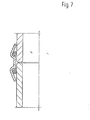
- Figure 7 shows an application for the frontal connection of socket-free pipes.
- the functionally decisive features of the embodiment according to FIG. 5 exist twice and are assigned to one another in mirror image.
- the conical surfaces can be concave or convex in the axial direction.
- FIG. 8 shows an application in the sealing fixing of a pipe in a pipe holding plate.
- the clamp body 2 shown is made of rubber with a Shore A hardness of 75.
- the heat exchanger tube has an outer diameter of 15 mm. It is made of copper.
- the pipe holding plate is made of sheet steel. It has a thickness of 3.5 mm.
- the clamping body is connected by the tension element 3, which rests on the holding surface 7 of the pipe holding plate.
- the profile of the clamping body is conically thickened both on the outside and on the inside.
- the smallest diameter is 14.4 mm inside.
- the subsequent ring membrane 12 extends parallel to the device axis.
- the clamping body is provided on the outside with a support bead 13. This is delimited on the outside by a semicircular profile that ends tangentially in the rear part in a plane extending perpendicular to the device axis and tangentially in the front part in a conical surface that encloses an angle of 10 ° with the device axis.
- the profile touches the conical surface of the opening of the tube holding plate, which is widened in the rear part, axially in the rear third of its extent.
- a conical surface is provided between the support bead 13 and the annular membrane 12. This is to facilitate the insertion of the device into the receiving opening. It encloses an angle of 45 ° with the device axis.
- the ring membrane 12 has a radial thickness of 0.3 mm with an axial length of 0.8 mm.
- the conical surface 4 encloses an angle of 18 ° with the device axis. It ends in the rear area in the same axial plane with the rear boundary of the profile and the pipe holding plate.
- FIG. 9 shows a version of the proposed locking and coupling device which is effective on one and two sides when used together on a water heater.
- This is shown in longitudinal section, consists of hard PVC and has two wall openings at the upper end, which on the one hand enclose the connecting pipes 14 for the supply and discharge of the water and on the other hand the insertion opening for the heating element 15.
- the wall openings are limited in a circle and expanded conically in the axial direction.
- internally cylindrically delimited clamping bodies 2 made of a non-compressible soft rubber are arranged, which touch the conical mouths of the wall openings.
- both clamping bodies In the area adjoining the conical surface 4 axially downward, both clamping bodies have an annular membrane 12 which rests under elastic prestress on the water pipes 14 or on the holder of the heating element 15. If an outward, ie upward, tensile force is exerted on the water pipes or on the holder of the heating element, this tensile force is transmitted via the ring membranes 12 to the clamping body 2, which leads to the fact that the clamping body in the radial direction between the surface of the Water pipes 14 or the surface of the holder 16 and the associated conical inner wall of the wall through breaks of the container 17 are pressed.
- Both the tubes 2 and the holder 6 as well as the container 1 are made of rigid materials, while the clamping bodies 5 are made of a non-compressible, flexible material. An axial pulling out of the tubes 14 or the holder 16 from the wall openings of the container 1 is therefore not possible.
- the holder 16 is delimited on the inside by two converging conical surfaces 4, which are most closely adjacent in the central part of the common, axial extent of the surface of the heating element 15.
- a clamping body 2 is arranged, adapted profile, which, as described above, consists of a soft, non-compressible material, the clamping body 2 in the areas lying axially outside of the conical surfaces 4 with each an annular membrane 12 is provided which, before the heating element 15 is inserted, has an inside diameter which is smaller than the outside diameter of the heating element 15. The annular membrane thereby lies sealingly against the surface of the heating element.
- a mounting sleeve 18 is used. This consists of thin-walled sheet metal and is divided in the axial direction at one point on the circumference. It can be rolled up to a diameter that is slightly smaller than the internal diameter of the ring membrane 12 due to the manufacturing process. The insertion into the ring membrane is accordingly simple. A simple expansion in the radial direction is then carried out, which can be done for example with the aid of a mandrel. It is stable if the surfaces of the mounting sleeve 18 opposite in the area of the separation are supported on one another in the circumferential direction. The mandrel can be removed and replaced by the heating element 15. If this is pushed through, the mounting sleeve 18 can easily be withdrawn from the clamping body 2, as a result of which the annular membrane 12 lies sealingly against the surface of the heating element 15.
- part 9 consists of sheet steel and is molded in one piece from the wall of a housing.
- the opening is rotationally symmetrical and has an inner cross section which widens conically in the rearward direction.
- the mutually opposite inner surfaces of the opening form an angle of 20 °.
- Part 8 is mounted concentrically in the sleeve. This has a cylindrical shape and forms the rear end of a pull hook. Part 8 is also made of steel and is therefore not as flexible as part 9.
- the clamping body 2 is arranged in the gap between part 8 and part 9. This essentially fills the gap and consists of a rubber-elastic material with a Shore A hardness of about 55. It can thus be easily deformed and easily inserted even before the part 8 is inserted Position the opening of part 9. The outside comes to rest on the conical surface 4 of the opening which is widened conically upwards and the flange 6 projecting outwards in the radial direction on the holding surface 7 of part 9.
- the inside diameter of the clamping body 2 is slightly larger in the area of the axial extension of the conical surface 4 than the outside diameter of the part 8 to be accommodated.
- the clearance in the present exemplary embodiment is approximately one tenth of a millimeter. It enables easy insertion and insertion of the part 8 to be received into the opening of the clamping body 2.
- the inner diameter of the clamping body 2 is reduced by the annular self-contained ring membrane 12 to a value which, due to the manufacturing process, is below the outer diameter of the part 8 to be accommodated radial thickness easy deformability.
- the deformation forces required for the complete insertion of the part 8 are therefore not very large and can be easily applied.
- the ring membrane 12 hugs the surface evenly and brings about a non-positive connection.
- Figure 11 refers to the use of the proposed kit for the mutual connection of straight abutting pipe ends.
- the part 9 forming a sleeve in this case is made of PVC and has a reduction in the internal cross-section in the central region of its axial extent and on both ends. This serves to guide the inserted tubes, with an inwardly projecting projection 19 of the sleeve being provided in the central region, which serves as a limit stop.
- the rotationally symmetrical clamping body 2 is inserted on both sides before the tubes are inserted.
- This consists of soft rubber and has a circumferential flange 6 which, after being pushed in, rests against the end holding surface of the sleeve and in this way ensures the correct assignment of the clamping surface to the conical surface 4 of the sleeve which is conically reduced in cross-section in the outward direction.
- the inside diameter of the clamping body in the area of the axial extent of the conical surface 4 is designed to be slightly larger than the outside diameter of the tube to be inserted. This can be easily inserted into the pre-assembled pipe connector.
- the clamping body is provided with a projection which is formed by an annular membrane 12 and which is axially adjacent to the axial extent of the conical surface 9.
- the inner diameter of the ring membrane, which is formed in one piece from the body of the clamping body, is slightly smaller than its outer diameter before the tube is inserted.
- a similar effect results when a flowable medium is introduced into the pipe, for example gas or water under pressure. Since the end wall of the tube is not sealed off on the projection 19, the flowable medium easily gets into the annular space 20. This is axially upstream of the clamping body in the region of its greatest radial extent, which is why leads to the fact that the pressure of the medium contained in the pipeline, similar to the case described above, leads to a radial compression of the clamping body 2 between the pipe wall and the conical surface 4 of the sleeve. The result is a good sealing result and a good axial fixation of the inserted tube.
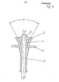
- FIG. 12 refers to an embodiment in which the two pipe ends to be connected are assigned to one another at an angle of 90 °.
- the sleeve spanning the two pipe ends is accordingly angled, but it has the same clamping body and the same function as described above.
- pipe connectors include all basic shapes required in the sanitary area, in particular T-pieces, cross pieces, elbows with different angles and transition pieces for the mutual connection of pipes of different diameters.
- the spatial position of the front end of the inserted tube is determined in the axial direction by the projection 19 and in the radial direction by a corresponding constriction of the inner diameter of the sleeve.
- the latter can surround the end of the pipe with a small distance, which makes it possible to compensate for angular displacements between the pipe ends to be connected.
- the stop can be provided with at least one axial opening in order to promote rapid pressure build-up in the free space 20.
- the clamping body is only inserted loosely into the sleeve.
- the assembly of the sprag is particularly easy.
- glue the sleeve and the clamping body In particular, very large, axially directed tensile forces can be better transmitted to the sleeve.
- the surfaces delimiting the clamping body in the radial direction are generally adapted to the surface shape of the surfaces to be fixed relative to one another. Noteworthy surface irregularities are generally not present here, which is why a corresponding design of the clamping body easily leads to the desired result. The production is accordingly simple and inexpensive.
- Figure 13 refers to an application example in which the clamping body is extended to form a cable grommet.
- This consists of an elongated hollow body made of soft rubber, which is inserted before the cable is inserted from above into the opening of the housing of a small electrical device, which is flared upwards. Then the cable to be picked up is inserted from below into the opening of the cable grommet.
- This is relatively simple insofar as the inner diameter of the cable grommet is smaller than the outer diameter of the cable only in the area of the annular membrane 12 arranged axially outside the conical surface 4.
- the ring membrane has a small wall thickness. It is easily expandable in the radial direction and freely movable.
- the degree of pressure of the clamping body 2 in the area of the conical surfaces 4 on the surface of the cable depends on the size of the cone angle oC and the size of the tensile forces introduced into the cable. Both can vary.
- the illustrated embodiment calls an angle of 30 °. This angle has proven to be particularly suitable with regard to the equipment of small electrical devices.
- the advantages that can be achieved with the proposed cable grommet are, in particular, particularly easy assembly and good fixing of the received cable in the axial direction. If the cable is subjected to tensile stress, this also results in a good seal of the passage point.
Landscapes
- Engineering & Computer Science (AREA)
- General Engineering & Computer Science (AREA)
- Mechanical Engineering (AREA)
- Clamps And Clips (AREA)
- Gasket Seals (AREA)
- Pressure Vessels And Lids Thereof (AREA)
- Joints With Sleeves (AREA)
- Quick-Acting Or Multi-Walled Pipe Joints (AREA)
Priority Applications (1)
| Application Number | Priority Date | Filing Date | Title |
|---|---|---|---|
| AT84105609T ATE28842T1 (de) | 1983-08-03 | 1984-05-17 | Verschluss- oder kupplungsvorrichtung. |
Applications Claiming Priority (10)
| Application Number | Priority Date | Filing Date | Title |
|---|---|---|---|
| DE8322349U | 1983-08-03 | ||
| DE19838322349U DE8322349U1 (de) | 1983-08-03 | 1983-08-03 | Vorrichtung zur dichten befestigung eines rohres in der oeffnung einer rohrhalteplatte |
| DE3408835A DE3408835C2 (de) | 1984-03-10 | 1984-03-10 | Warmwasserbereiter |
| DE3408835 | 1984-03-10 | ||
| DE3409906 | 1984-03-17 | ||
| DE19843409907 DE3409907A1 (de) | 1984-03-17 | 1984-03-17 | Bausatz zur festlegung des endes eines saeulenfoermigen koerpers in einer huelse |
| DE3409907 | 1984-03-17 | ||
| DE3409906A DE3409906C2 (de) | 1984-03-17 | 1984-03-17 | Kabeltülle |
| DE3413155 | 1984-04-07 | ||
| DE19843413155 DE3413155A1 (de) | 1983-08-03 | 1984-04-07 | Verschluss- oder kupplungsvorrichtung |
Publications (3)
| Publication Number | Publication Date |
|---|---|
| EP0133455A2 true EP0133455A2 (fr) | 1985-02-27 |
| EP0133455A3 EP0133455A3 (en) | 1985-07-10 |
| EP0133455B1 EP0133455B1 (fr) | 1987-08-12 |
Family
ID=27510792
Family Applications (1)
| Application Number | Title | Priority Date | Filing Date |
|---|---|---|---|
| EP84105609A Expired EP0133455B1 (fr) | 1983-08-03 | 1984-05-17 | Dispositif de fermeture ou d'accouplement |
Country Status (6)
| Country | Link |
|---|---|
| EP (1) | EP0133455B1 (fr) |
| JP (1) | JPH0637655U (fr) |
| BR (1) | BR8403871A (fr) |
| CA (1) | CA1252810A (fr) |
| DE (1) | DE3465282D1 (fr) |
| MX (1) | MX159390A (fr) |
Cited By (3)
| Publication number | Priority date | Publication date | Assignee | Title |
|---|---|---|---|---|
| EP0745812A3 (fr) * | 1995-05-31 | 1998-07-01 | Robert Bosch Gmbh | Vase d'expansion pour installation de chauffage à eau |
| GB2331865A (en) * | 1997-11-28 | 1999-06-02 | Motorola Bv | A sealing arrangement |
| WO2020011405A1 (fr) * | 2018-07-10 | 2020-01-16 | Robert Bosch Gmbh | Fixation d'un couvercle sur un boîtier |
Families Citing this family (1)
| Publication number | Priority date | Publication date | Assignee | Title |
|---|---|---|---|---|
| JP4205966B2 (ja) * | 2003-02-13 | 2009-01-07 | Nok株式会社 | 密封装置 |
Family Cites Families (16)
| Publication number | Priority date | Publication date | Assignee | Title |
|---|---|---|---|---|
| AT4198B (fr) * | 1899-12-09 | 1901-05-25 | Fluegge Fa C | |
| BE459360A (fr) * | 1944-07-18 | |||
| FR926488A (fr) * | 1946-04-12 | 1947-10-02 | Anciens Etablissements Panhard | Joint d'étanchéité notamment pour le raccord de tuyauteries sur des réservoirs |
| DE802293C (de) * | 1949-09-04 | 1951-02-08 | Mannesmann Ag | Leicht zusammenfuegbare, zugfeste Schnellverbindung von Rohren |
| US2674390A (en) * | 1950-03-31 | 1954-04-06 | Leer S Curacao N V Van | Joint or closure |
| CH396534A (de) * | 1962-06-28 | 1965-07-31 | Hawle Erwin | Verbindungs- bzw. Übergangsstück für glatte Rohre, insbesondere Kunststoffrohre |
| CH406756A (de) * | 1962-09-08 | 1966-01-31 | Keller Emil | Steckkupplung für Druckrohre |
| US3462175A (en) * | 1965-04-20 | 1969-08-19 | Sonel | Connector for unthreaded pipe,and method of making the same |
| DE6937817U (de) * | 1969-09-27 | 1971-05-13 | Muecher Hermann | Dichtung von rohrverbindungsstellen. |
| DE1949746C3 (de) * | 1969-10-02 | 1974-03-07 | Hermann Muecher Muecher-Ringe, 5830 Schwelm | Dichtung von Rohrverbindungsstellen |
| BE750597A (fr) * | 1970-05-19 | 1970-11-03 | Amp Inc | Joint tubulaire hermetique d'assemblage, |
| JPS4934018A (fr) * | 1972-07-31 | 1974-03-29 | ||
| DD100070A1 (fr) * | 1972-10-02 | 1973-09-05 | ||
| DE2639739A1 (de) * | 1976-09-03 | 1978-03-16 | Uwe Tiedt | Loesbare, druckdichte steckverbindung |
| US4350351A (en) * | 1980-12-17 | 1982-09-21 | Martin A Eugene | Manhole joint gasket assembly and joint formed therewith |
| FR2520840B1 (fr) * | 1982-01-29 | 1986-03-07 | Aldes | Dispositif de fixation d'un element tubulaire de ventilation dans une reservation menagee dans une paroi |
-
1984
- 1984-05-17 EP EP84105609A patent/EP0133455B1/fr not_active Expired
- 1984-05-17 DE DE8484105609T patent/DE3465282D1/de not_active Expired
- 1984-06-15 MX MX201684A patent/MX159390A/es unknown
- 1984-08-02 BR BR8403871A patent/BR8403871A/pt not_active IP Right Cessation
- 1984-08-03 CA CA000460329A patent/CA1252810A/fr not_active Expired
-
1991
- 1991-04-19 JP JP026429U patent/JPH0637655U/ja active Pending
Cited By (7)
| Publication number | Priority date | Publication date | Assignee | Title |
|---|---|---|---|---|
| EP0745812A3 (fr) * | 1995-05-31 | 1998-07-01 | Robert Bosch Gmbh | Vase d'expansion pour installation de chauffage à eau |
| GB2331865A (en) * | 1997-11-28 | 1999-06-02 | Motorola Bv | A sealing arrangement |
| GB2331865B (en) * | 1997-11-28 | 2000-02-23 | Motorola Bv | A sealing arrangement |
| WO2020011405A1 (fr) * | 2018-07-10 | 2020-01-16 | Robert Bosch Gmbh | Fixation d'un couvercle sur un boîtier |
| CN112352121A (zh) * | 2018-07-10 | 2021-02-09 | 罗伯特·博世有限公司 | 盖在壳体处的固定结构 |
| CN112352121B (zh) * | 2018-07-10 | 2023-03-07 | 罗伯特·博世有限公司 | 盖在壳体处的固定结构 |
| US11976727B2 (en) | 2018-07-10 | 2024-05-07 | Robert Bosch Gmbh | Fastening of a cover to a housing |
Also Published As
| Publication number | Publication date |
|---|---|
| EP0133455A3 (en) | 1985-07-10 |
| CA1252810A (fr) | 1989-04-18 |
| MX159390A (es) | 1989-05-22 |
| EP0133455B1 (fr) | 1987-08-12 |
| BR8403871A (pt) | 1985-07-09 |
| JPH0637655U (ja) | 1994-05-20 |
| DE3465282D1 (en) | 1987-09-17 |
Similar Documents
| Publication | Publication Date | Title |
|---|---|---|
| DE3117901C2 (de) | Verfahren zum druckdichten Verbinden eines Stahlrohres mit einer Metallhülse sowie Vorrichtung zur Durchführung des Verfahrens | |
| DE69701379T2 (de) | Rohrverbindung | |
| DE60022945T2 (de) | Schnellkupplung für ein flexibles Rohr | |
| DE3610085C2 (fr) | ||
| DE2832614A1 (de) | Verbindungsstueck fuer rohrleitungen | |
| DE2521930C2 (de) | Rohrverbindungsstück | |
| EP1840437A2 (fr) | Dispositif d'étanchéité pour un raccord rapide | |
| DE2750986A1 (de) | Rohrverbindung | |
| DE29900796U1 (de) | Vorrichtung zum Verbinden eines Rohrstutzens, rohrförmigen Armaturenteils oder Fittings mit einem Rohr | |
| DE3443942C2 (de) | Rohrverbindung mit mindestens einem Abzweigstutzen | |
| DE1925171A1 (de) | Verbindungsvorrichtung oder Kupplung | |
| EP0133455A2 (fr) | Dispositif de fermeture ou d'accouplement | |
| EP4661228A2 (fr) | Joint d'étanchéité pour tuyau unique | |
| EP0546405B1 (fr) | Raccord de tuyaux | |
| EP0797037A2 (fr) | Raccord de tuyaux à assemblage rapide | |
| DE29807763U1 (de) | Anschlußvorrichtung zum schnellen und lösbaren Anschluß von Rohrleitungen | |
| DE3031687C2 (de) | Vorrichtung zum Schutz der Endbereiche von Rohren gegen mechanische Beschädigungen | |
| DE69313956T2 (de) | Schlauch mit radialer Spannvorrichtung zum Verbinden mit einem Rohrende; Schlauchverbindung mit diesem Schlauch | |
| DE19731563A1 (de) | Verfahren zur Herstellung einer dichten und festen Rohrverbindung | |
| DE2818284A1 (de) | Dichte verbindungsvorrichtung | |
| DE10130707B4 (de) | Vorrichtung zum Durchführen von Kabeln, Leitungen und dergleichen durch eine Gebäudewand | |
| EP0070561A2 (fr) | Dispositif pour raccorder deux tuyaux de façon hermétique aux gaz et aux liquides | |
| DE19909394B4 (de) | Lösbare Steckverbindung für den Anschluß von Rohrleitungen | |
| DE9417117U1 (de) | Anordnung zur dichten Durchführung eines Kabels o.dgl. durch eine Wandung | |
| DE2738454C3 (de) | Lösbare Muffensteckverbindung |
Legal Events
| Date | Code | Title | Description |
|---|---|---|---|
| PUAI | Public reference made under article 153(3) epc to a published international application that has entered the european phase |
Free format text: ORIGINAL CODE: 0009012 |
|
| AK | Designated contracting states |
Designated state(s): AT BE CH DE FR GB IT LI LU NL SE |
|
| PUAL | Search report despatched |
Free format text: ORIGINAL CODE: 0009013 |
|
| AK | Designated contracting states |
Designated state(s): AT BE CH DE FR GB IT LI LU NL SE |
|
| 17P | Request for examination filed |
Effective date: 19850521 |
|
| ITF | It: translation for a ep patent filed | ||
| GRAA | (expected) grant |
Free format text: ORIGINAL CODE: 0009210 |
|
| AK | Designated contracting states |
Kind code of ref document: B1 Designated state(s): AT BE CH DE FR GB IT LI LU NL SE |
|
| REF | Corresponds to: |
Ref document number: 28842 Country of ref document: AT Date of ref document: 19870815 Kind code of ref document: T |
|
| ET | Fr: translation filed | ||
| REF | Corresponds to: |
Ref document number: 3465282 Country of ref document: DE Date of ref document: 19870917 |
|
| PLBE | No opposition filed within time limit |
Free format text: ORIGINAL CODE: 0009261 |
|
| STAA | Information on the status of an ep patent application or granted ep patent |
Free format text: STATUS: NO OPPOSITION FILED WITHIN TIME LIMIT |
|
| 26N | No opposition filed | ||
| ITTA | It: last paid annual fee | ||
| EPTA | Lu: last paid annual fee | ||
| EAL | Se: european patent in force in sweden |
Ref document number: 84105609.6 |
|
| PGFP | Annual fee paid to national office [announced via postgrant information from national office to epo] |
Ref country code: SE Payment date: 19970409 Year of fee payment: 14 |
|
| PGFP | Annual fee paid to national office [announced via postgrant information from national office to epo] |
Ref country code: DE Payment date: 19970410 Year of fee payment: 14 |
|
| PGFP | Annual fee paid to national office [announced via postgrant information from national office to epo] |
Ref country code: GB Payment date: 19970418 Year of fee payment: 14 |
|
| PGFP | Annual fee paid to national office [announced via postgrant information from national office to epo] |
Ref country code: LU Payment date: 19970507 Year of fee payment: 14 |
|
| PGFP | Annual fee paid to national office [announced via postgrant information from national office to epo] |
Ref country code: AT Payment date: 19970512 Year of fee payment: 14 |
|
| PGFP | Annual fee paid to national office [announced via postgrant information from national office to epo] |
Ref country code: BE Payment date: 19970515 Year of fee payment: 14 |
|
| PGFP | Annual fee paid to national office [announced via postgrant information from national office to epo] |
Ref country code: FR Payment date: 19970516 Year of fee payment: 14 |
|
| PGFP | Annual fee paid to national office [announced via postgrant information from national office to epo] |
Ref country code: NL Payment date: 19970530 Year of fee payment: 14 |
|
| PG25 | Lapsed in a contracting state [announced via postgrant information from national office to epo] |
Ref country code: DE Effective date: 19970717 |
|
| PGFP | Annual fee paid to national office [announced via postgrant information from national office to epo] |
Ref country code: CH Payment date: 19970728 Year of fee payment: 14 |
|
| PG25 | Lapsed in a contracting state [announced via postgrant information from national office to epo] |
Ref country code: LU Free format text: LAPSE BECAUSE OF NON-PAYMENT OF DUE FEES Effective date: 19980517 Ref country code: GB Free format text: LAPSE BECAUSE OF NON-PAYMENT OF DUE FEES Effective date: 19980517 Ref country code: AT Free format text: LAPSE BECAUSE OF NON-PAYMENT OF DUE FEES Effective date: 19980517 |
|
| PG25 | Lapsed in a contracting state [announced via postgrant information from national office to epo] |
Ref country code: SE Free format text: LAPSE BECAUSE OF NON-PAYMENT OF DUE FEES Effective date: 19980518 |
|
| PG25 | Lapsed in a contracting state [announced via postgrant information from national office to epo] |
Ref country code: LI Free format text: LAPSE BECAUSE OF NON-PAYMENT OF DUE FEES Effective date: 19980531 Ref country code: FR Free format text: LAPSE BECAUSE OF NON-PAYMENT OF DUE FEES Effective date: 19980531 Ref country code: CH Free format text: LAPSE BECAUSE OF NON-PAYMENT OF DUE FEES Effective date: 19980531 Ref country code: BE Free format text: LAPSE BECAUSE OF NON-PAYMENT OF DUE FEES Effective date: 19980531 |
|
| BERE | Be: lapsed |
Owner name: FIRMA CARL FREUDENBERG Effective date: 19980531 |
|
| PG25 | Lapsed in a contracting state [announced via postgrant information from national office to epo] |
Ref country code: NL Free format text: LAPSE BECAUSE OF NON-PAYMENT OF DUE FEES Effective date: 19981201 |
|
| GBPC | Gb: european patent ceased through non-payment of renewal fee |
Effective date: 19980517 |
|
| REG | Reference to a national code |
Ref country code: CH Ref legal event code: PL |
|
| EUG | Se: european patent has lapsed |
Ref document number: 84105609.6 |
|
| NLV4 | Nl: lapsed or anulled due to non-payment of the annual fee |
Effective date: 19981201 |
|
| REG | Reference to a national code |
Ref country code: FR Ref legal event code: ST |